Praise for Fundamentals of Software Architecture
Neal and Mark aren’t just outstanding software architects; they are also exceptional teachers. With Fundamentals of Software Architecture, they have managed to condense the sprawling topic of architecture into a concise work that reflects their decades of experience. Whether you’re new to the role or you’ve been a practicing architect for many years, this book will help you be better at your job. I only wish they’d written this earlier in my career.
Nathaniel Schutta, Architect as a Service, ntschutta.io
Mark and Neal set out to achieve a formidable goal—to elucidate the many, layered fundamentals required to excel in software architecture—and they completed their quest. The software architecture field continuously evolves, and the role requires a daunting breadth and depth of knowledge and skills. This book will serve as a guide for many as they navigate their journey to software architecture mastery.
Rebecca J. Parsons, CTO, ThoughtWorks
Mark and Neal truly capture real world advice for technologists to drive architecture excellence. They achieve this by identifying common architecture characteristics and the trade-offs that are necessary to drive success.
Cassie Shum, Technical Director, ThoughtWorks
Fundamentals of Software Architecture
An Engineering Approach
Mark Richards and Neal Ford
Fundamentals of Software Architecture
by Mark Richards and Neal Ford
Copyright © 2020 Mark Richards, Neal Ford. All rights reserved.
Printed in the United States of America.
Published by O’Reilly Media, Inc., 1005 Gravenstein Highway North, Sebastopol, CA 95472.
O’Reilly books may be purchased for educational, business, or sales promotional use. Online editions are also available for most titles (http://oreilly.com). For more information, contact our corporate/institutional sales department: 800-998-9938 or corporate@oreilly.com.
- Acquisitions Editor: Chris Guzikowski
- Development Editors: Alicia Young and Virginia Wilson
- Production Editor: Christopher Faucher
- Copyeditor: Sonia Saruba
- Proofreader: Amanda Kersey
- Indexer: Ellen Troutman-Zaig
- Interior Designer: David Futato
- Cover Designer: Karen Montgomery
- Illustrator: Rebecca Demarest
- February 2020: First Edition
Revision History for the First Edition
- 2020-01-27: First Release
See http://oreilly.com/catalog/errata.csp?isbn=9781492043454 for release details.
The O’Reilly logo is a registered trademark of O’Reilly Media, Inc. Fundamentals of Software Architecture, the cover image, and related trade dress are trademarks of O’Reilly Media, Inc.
The views expressed in this work are those of the authors, and do not represent the publisher’s views. While the publisher and the authors have used good faith efforts to ensure that the information and instructions contained in this work are accurate, the publisher and the authors disclaim all responsibility for errors or omissions, including without limitation responsibility for damages resulting from the use of or reliance on this work. Use of the information and instructions contained in this work is at your own risk. If any code samples or other technology this work contains or describes is subject to open source licenses or the intellectual property rights of others, it is your responsibility to ensure that your use thereof complies with such licenses and/or rights.
978-1-492-04345-4
[LSI]
Preface: Invalidating Axioms
- Axiom
A statement or proposition which is regarded as being established, accepted, or self-evidently true.
Mathematicians create theories based on axioms, assumptions for things indisputably true. Software architects also build theories atop axioms, but the software world is, well, softer than mathematics: fundamental things continue to change at a rapid pace, including the axioms we base our theories upon.
The software development ecosystem exists in a constant state of dynamic equilibrium: while it exists in a balanced state at any given point in time, it exhibits dynamic behavior over the long term. A great modern example of the nature of this ecosystem follows the ascension of containerization and the attendant changes: tools like Kubernetes didn’t exist a decade ago, yet now entire software conferences exist to service its users. The software ecosystem changes chaotically: one small change causes another small change; when repeated hundreds of times, it generates a new ecosystem.
Architects have an important responsibility to question assumptions and axioms left over from previous eras. Many of the books about software architecture were written in an era that only barely resembles the current world. In fact, the authors believe that we must question fundamental axioms on a regular basis, in light of improved engineering practices, operational ecosystems, software development processes—everything that makes up the messy, dynamic equilibrium where architects and developers work each day.
Careful observers of software architecture over time witnessed an evolution of capabilities. Starting with the engineering practices of Extreme Programming, continuing with Continuous Delivery, the DevOps revolution, microservices, containerization, and now cloud-based resources, all of these innovations led to new capabilities and trade-offs. As capabilities changed, so did architects’ perspectives on the industry. For many years, the tongue-in-cheek definition of software architecture was “the stuff that’s hard to change later.” Later, the microservices architecture style appeared, where change is a first-class design consideration.
Each new era requires new practices, tools, measurements, patterns, and a host of other changes. This book looks at software architecture in modern light, taking into account all the innovations from the last decade, along with some new metrics and measures suited to today’s new structures and perspectives.
The subtitle of our book is “An Engineering Approach.” Developers have long wished to change software development from a craft, where skilled artisans can create one-off works, to an engineering discipline, which implies repeatability, rigor, and effective analysis. While software engineering still lags behind other types of engineering disciplines by many orders of magnitude (to be fair, software is a very young discipline compared to most other types of engineering), architects have made huge improvements, which we’ll discuss. In particular, modern Agile engineering practices have allowed great strides in the types of systems that architects design.
We also address the critically important issue of trade-off analysis. As a software developer, it’s easy to become enamored with a particular technology or approach. But architects must always soberly assess the good, bad, and ugly of every choice, and virtually nothing in the real world offers convenient binary choices—everything is a trade-off. Given this pragmatic perspective, we strive to eliminate value judgments about technology and instead focus on analyzing trade-offs to equip our readers with an analytic eye toward technology choices.
This book won’t make someone a software architecture overnight—it’s a nuanced field with many facets. We want to provide existing and burgeoning architects a good modern overview of software architecture and its many aspects, from structure to soft skills. While this book covers well-known patterns, we take a new approach, leaning on lessons learned, tools, engineering practices, and other input. We take many existing axioms in software architecture and rethink them in light of the current ecosystem, and design architectures, taking the modern landscape into account.
Conventions Used in This Book
The following typographical conventions are used in this book:
- Italic
-
Indicates new terms, URLs, email addresses, filenames, and file extensions.
Constant width-
Used for program listings, as well as within paragraphs to refer to program elements such as variable or function names, databases, data types, environment variables, statements, and keywords.
Constant width bold-
Shows commands or other text that should be typed literally by the user.
Constant width italic-
Shows text that should be replaced with user-supplied values or by values determined by context.
Tip
This element signifies a tip or suggestion.
Using Code Examples
Supplemental material (code examples, exercises, etc.) is available for download at http://fundamentalsofsoftwarearchitecture.com.
If you have a technical question or a problem using the code examples, please send email to bookquestions@oreilly.com.
This book is here to help you get your job done. In general, if example code is offered with this book, you may use it in your programs and documentation. You do not need to contact us for permission unless you’re reproducing a significant portion of the code. For example, writing a program that uses several chunks of code from this book does not require permission. Selling or distributing examples from O’Reilly books does require permission. Answering a question by citing this book and quoting example code does not require permission. Incorporating a significant amount of example code from this book into your product’s documentation does require permission.
We appreciate, but generally do not require, attribution. An attribution usually includes the title, author, publisher, and ISBN. For example: “Fundamentals of Software Architecture by Mark Richards and Neal Ford (O’Reilly). Copyright 2020 Mark Richards, Neal Ford, 978-1-492-04345-4.”
If you feel your use of code examples falls outside fair use or the permission given above, feel free to contact us at permissions@oreilly.com.
O’Reilly Online Learning
Note
For more than 40 years, O’Reilly Media has provided technology and business training, knowledge, and insight to help companies succeed.
Our unique network of experts and innovators share their knowledge and expertise through books, articles, conferences, and our online learning platform. O’Reilly’s online learning platform gives you on-demand access to live training courses, in-depth learning paths, interactive coding environments, and a vast collection of text and video from O’Reilly and 200+ other publishers. For more information, please visit http://oreilly.com.
How to Contact Us
Please address comments and questions concerning this book to the publisher:
- O’Reilly Media, Inc.
- 1005 Gravenstein Highway North
- Sebastopol, CA 95472
- 800-998-9938 (in the United States or Canada)
- 707-829-0515 (international or local)
- 707-829-0104 (fax)
We have a web page for this book, where we list errata, examples, and any additional information. You can access this page at https://oreil.ly/fundamentals-of-software-architecture.
Email bookquestions@oreilly.com to comment or ask technical questions about this book.
For more information about our books, courses, conferences, and news, see our website at http://www.oreilly.com.
Find us on Facebook: http://facebook.com/oreilly
Follow us on Twitter: http://twitter.com/oreillymedia
Watch us on YouTube: http://www.youtube.com/oreillymedia
Acknowledgments
Mark and Neal would like to thank all the people who attended our classes, workshops, conference sessions, user group meetings, as well as all the other people who listened to versions of this material and provided invaluable feedback. We would also like to thank the publishing team at O’Reilly, who made this as painless an experience as writing a book can be. We would also like to thank No Stuff Just Fluff director Jay Zimmerman for creating a conference series that allows good technical content to grow and spread, and all the other speakers whose feedback and tear-soaked shoulders we appreciate. We would also like to thank a few random oases of sanity-preserving and idea-sparking groups that have names like Pasty Geeks and the Hacker B&B.
Acknowledgments from Mark Richards
In addition to the preceding acknowledgments, I would like to thank my lovely wife, Rebecca. Taking everything else on at home and sacrificing the opportunity to work on your own book allowed me to do additional consulting gigs and speak at more conferences and training classes, giving me the opportunity to practice and hone the material for this book. You are the best.
Acknowledgments from Neal Ford
Neal would like to thank his extended family, ThoughtWorks as a collective, and Rebecca Parsons and Martin Fowler as individual parts of it. ThoughtWorks is an extraordinary group who manage to produce value for customers while keeping a keen eye toward why things work so that that we can improve them. ThoughtWorks supported this book in many myriad ways and continues to grow ThoughtWorkers who challenge and inspire every day. Neal would also like to thank our neighborhood cocktail club for a regular escape from routine. Lastly, Neal would like to thank his wife, Candy, whose tolerance for things like book writing and conference speaking apparently knows no bounds. For decades she’s kept me grounded and sane enough to function, and I hope she will for decades more as the love of my life.
Chapter 1. Introduction
The job “software architect” appears near the top of numerous lists of best jobs across the world.
Architecture is about the important stuff…whatever that is.
Ralph Johnson
When pressed, we created the mindmap shown in Figure 1-1, which is woefully incomplete but indicative of the scope of software architecture. We will, in fact, offer our definition of software architecture shortly.
Second, as illustrated in the mindmap, the role of software architect embodies a massive amount and scope of responsibility that continues to expand. A decade ago, software architects dealt only with the purely technical aspects of architecture, like modularity, components, and patterns. Since then, because of new architectural styles that leverage a wider swath of capabilities (like microservices), the role of software architect has expanded. We cover the many intersections of architecture and the remainder of the organization in “Intersection of Architecture and…”.
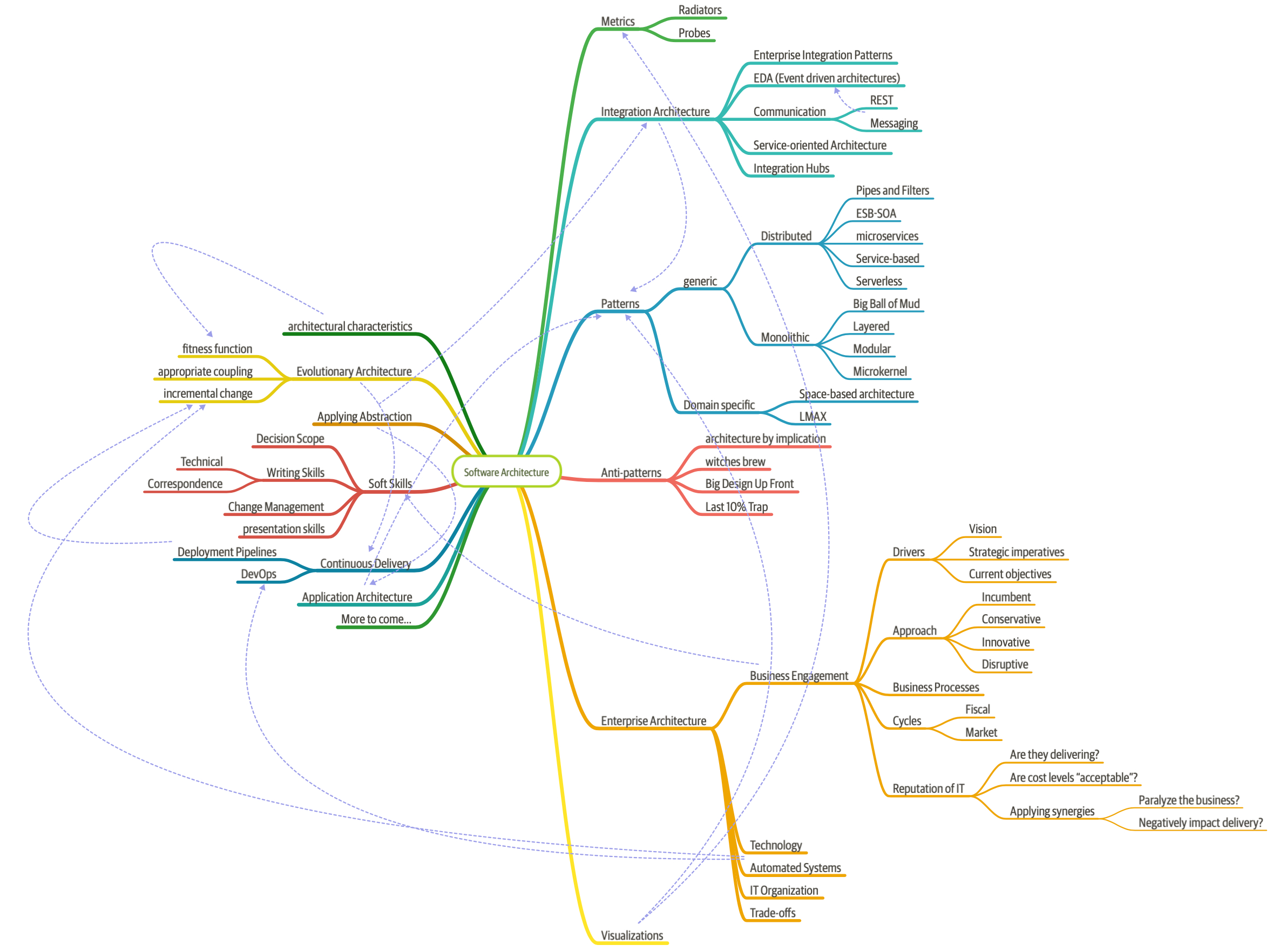
Figure 1-1. The responsibilities of a software architect encompass technical abilities, soft skills, operational awareness, and a host of others
Third, software architecture is a constantly moving target because of the rapidly evolving software development ecosystem. Any definition cast today will be hopelessly outdated in a few years. The Wikipedia definition of software architecture provides a reasonable overview, but many statements are outdated, such as “Software architecture is about making fundamental structural choices which are costly to change once implemented.” Yet architects designed modern architectural styles like microservices with the idea of incremental built in—it is no longer expensive to make structural changes in microservices. Of course, that capability means trade-offs with other concerns, such as coupling. Many books on software architecture treat it as a static problem; once solved, we can safely ignore it. However, we recognize the inherent dynamic nature of software architecture, including the definition itself, throughout the book.
Fourth, much of the material about software architecture has only historical relevance. Readers of the Wikipedia page won’t fail to notice the bewildering array of acronyms and cross-references to an entire universe of knowledge. Yet, many of these acronyms represent outdated or failed attempts. Even solutions that were perfectly valid a few years ago cannot work now because the context has changed. The history of software architecture is littered with things architects have tried, only to realize the damaging side effects. We cover many of those lessons in this book.
Why a book on software architecture fundamentals now? The scope of software architecture isn’t the only part of the development world that constantly changes. New technologies, techniques, capabilities…in fact, it’s easier to find things that haven’t changed over the last decade than to list all the changes. Software architects must make decisions within this constantly changing ecosystem. Because everything changes, including foundations upon which we make decisions, architects should reexamine some core axioms that informed earlier writing about software architecture. For example, earlier books about software architecture don’t consider the impact of DevOps because it didn’t exist when these books were written.
Defining Software Architecture
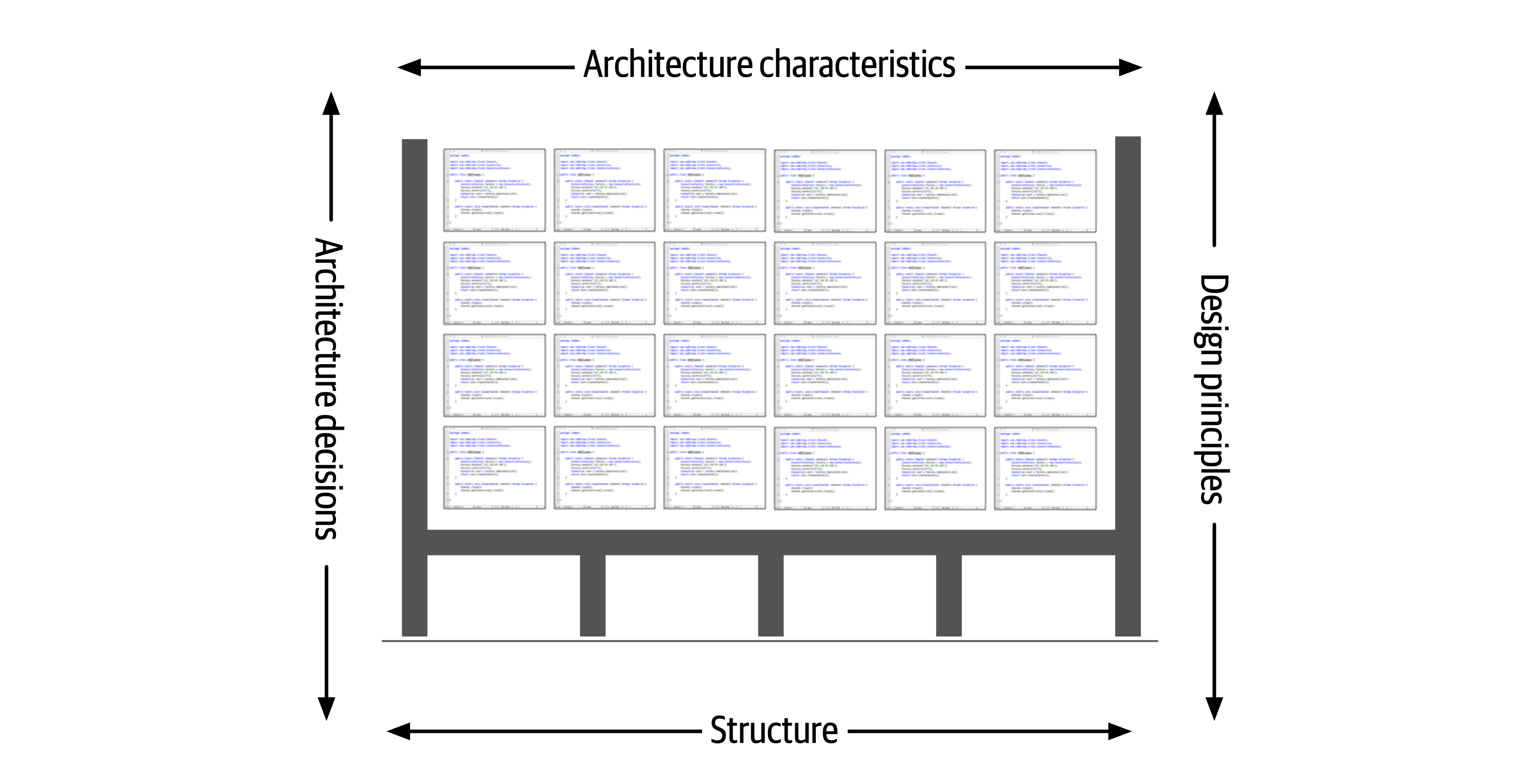
Figure 1-2. Architecture consists of the structure combined with architecture characteristics (“-ilities”), architecture decisions, and design principles
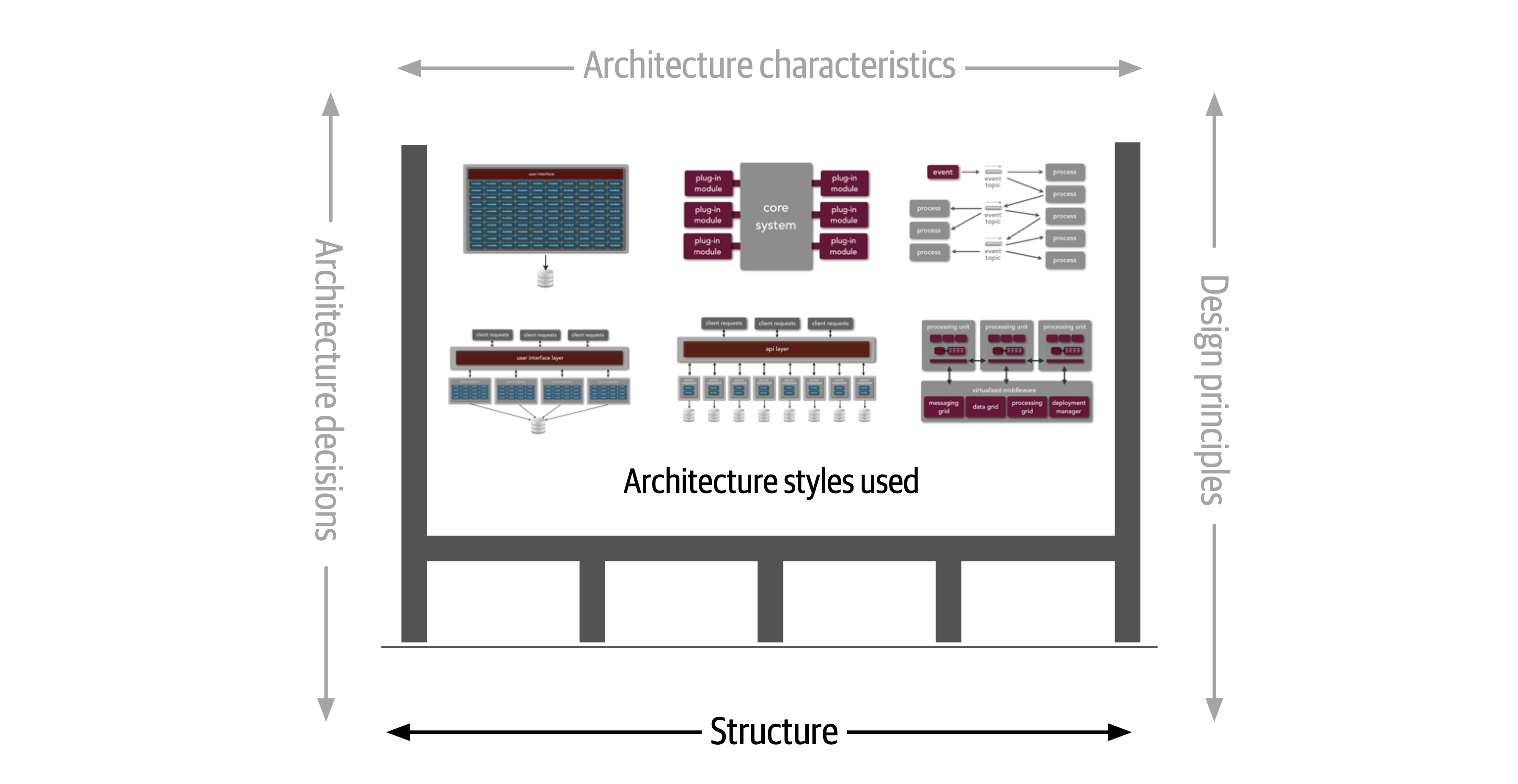
Figure 1-3. Structure refers to the type of architecture styles used in the system
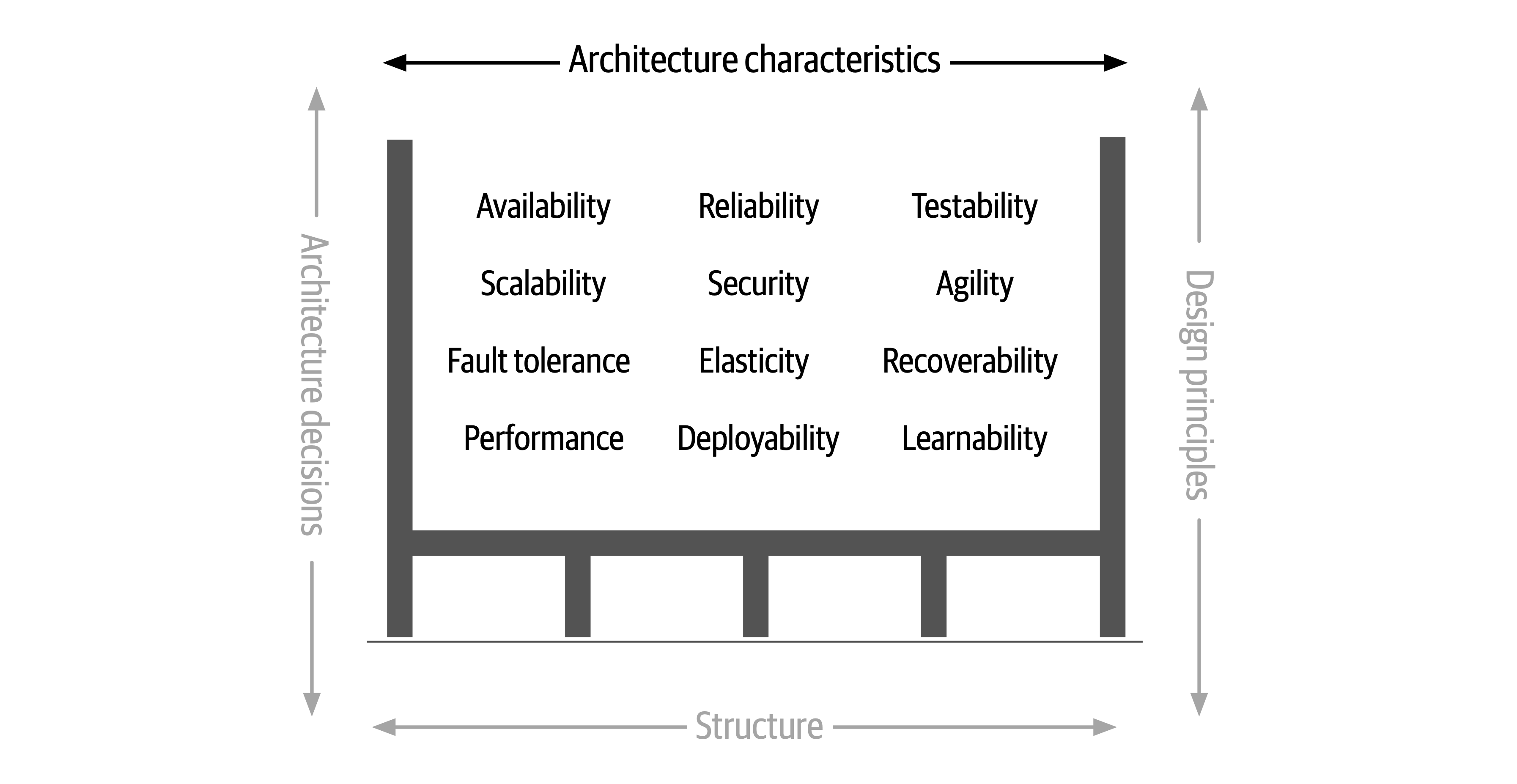
Figure 1-4. Architecture characteristics refers to the “-ilities” that the system must support
The next
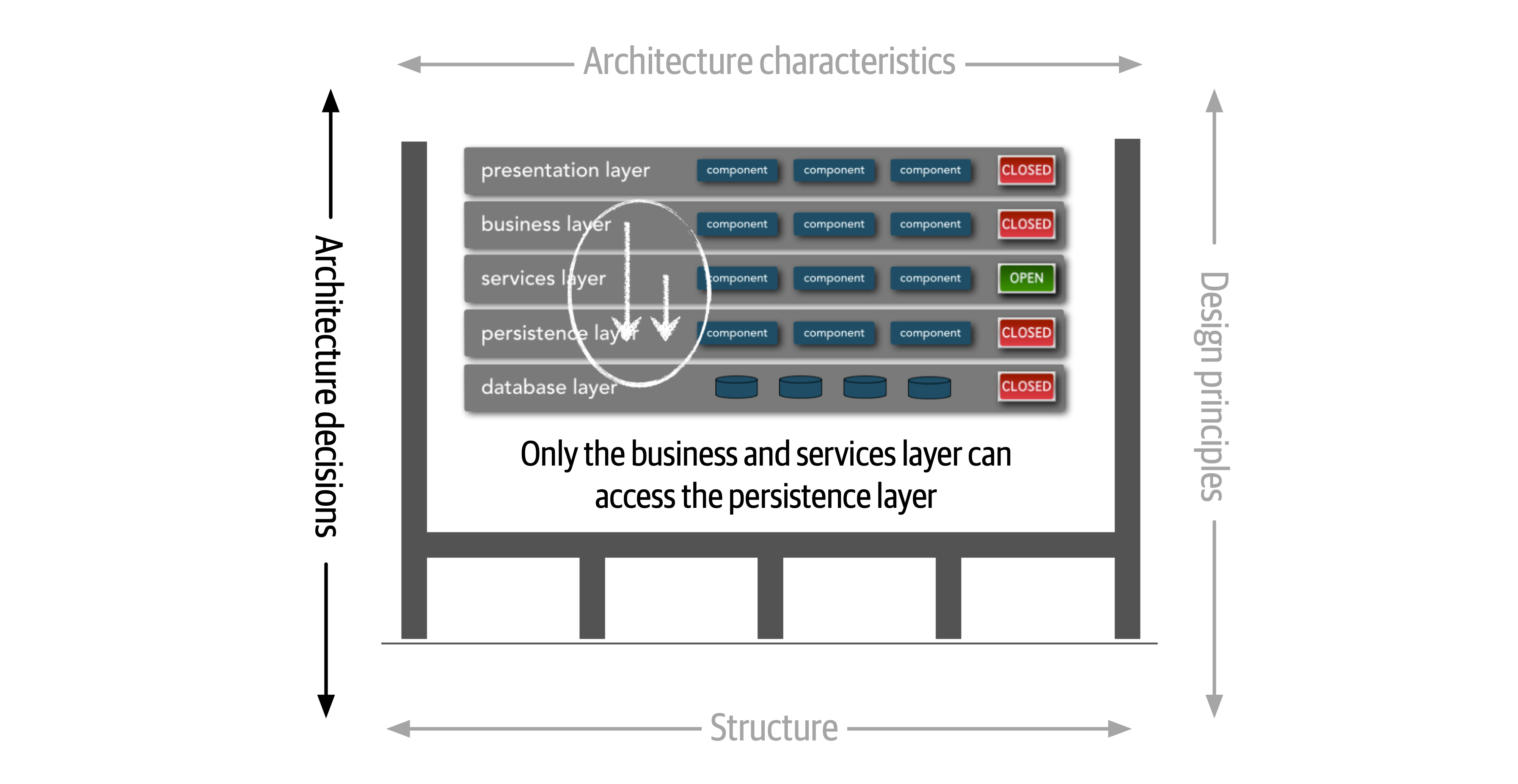
Figure 1-5. Architecture decisions are rules for constructing systems
If a particular architecture decision cannot be implemented in one part of the system due to some condition or other constraint, that decision (or rule) can be broken through something called a variance.
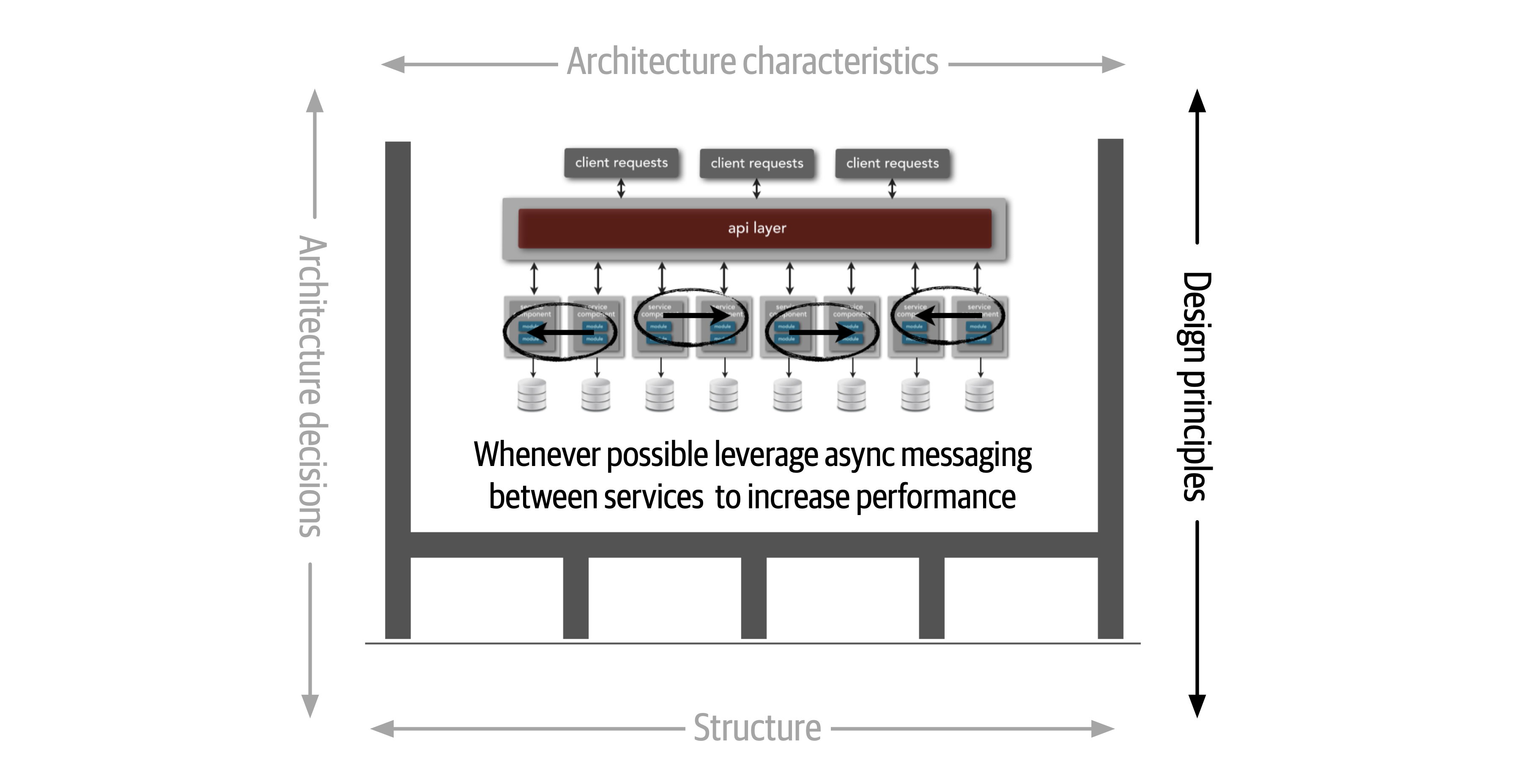
Figure 1-6. Design principles are guidelines for constructing systems
Expectations of an Architect
There are eight core expectations placed on a software architect, irrespective of any given role, title, or job description:
-
Make architecture decisions
-
Continually analyze the architecture
-
Keep current with latest trends
-
Ensure compliance with decisions
-
Diverse exposure and experience
-
Have business domain knowledge
-
Possess interpersonal skills
-
Understand and navigate politics
The first key to effectiveness and success in the software architect role depends on understanding and practicing each of these expectations.
Make Architecture Decisions
An architect is expected to define the architecture decisions and design principles used to guide technology decisions within the team, the department, or across the enterprise.
Guide is the key operative word in this first expectation. An architect should guide rather than specify technology choices. For example, an architect might make a decision to use React.js for frontend development. In this case, the architect is making a technical decision rather than an architectural decision or design principle that will help the development team make choices. An architect should instead instruct development teams to use a reactive-based framework for frontend web development, hence guiding the development team in making the choice between Angular, Elm, React.js, Vue, or any of the other reactive-based web frameworks.
Continually Analyze the Architecture
An architect is expected to continually analyze the architecture and current technology environment and then recommend solutions for improvement.
This expectation of an architect refers to architecture vitality, which assesses how viable the architecture that was defined three or more years ago is today, given changes in both business and technology.
Other forgotten aspects of this expectation that architects frequently forget are testing and release environments. Agility for code modification has obvious benefits, but if it takes teams weeks to test changes and months for releases, then architects cannot achieve agility in the overall architecture.
An architect must holistically analyze changes in technology and problem domains to determine the soundness of the architecture. While this kind of consideration rarely appears in a job posting, architects must meet this expectation to keep applications relevant.
Keep Current with Latest Trends
An architect is expected to keep current with the latest technology and industry trends.
Developers must keep up to date on the latest technologies they use on a daily basis to remain relevant (and to retain a job!). An architect has an even more critical requirement to keep current on the latest technical and industry trends. The decisions an architect makes tend to be long-lasting and difficult to change. Understanding and following key trends helps the architect prepare for the future and make the correct decision.
Ensure Compliance with Decisions
An architect is expected to ensure compliance with architecture decisions and design principles.
Ensuring compliance means that the architect is continually verifying that development teams are following the architecture decisions and design principles defined, documented, and communicated by the architect. Consider the scenario where an architect makes a decision to restrict access to the database in a layered architecture to only the business and services layers (and not the presentation layer). This means that the presentation layer must go through all layers of the architecture to make even the simplest of database calls. A user interface developer might disagree with this decision and access the database (or the persistence layer) directly for performance reasons. However, the architect made that architecture decision for a specific reason: to control change. By closing the layers, database changes can be made without impacting the presentation layer. By not ensuring compliance with architecture decisions, violations like this can occur, the architecture will not meet the required architectural characteristics (“-ilities”), and the application or system will not work as expected.
In Chapter 6 we talk more about measuring compliance using automated fitness functions and automated tools.
Diverse Exposure and Experience
An architect is expected to have exposure to multiple and diverse technologies, frameworks, platforms, and environments.
This expectation does not mean an architect must be an expert in every framework, platform, and language, but rather that an architect must at least be familiar with a variety of technologies. Most environments these days are heterogeneous, and at a minimum an architect should know how to interface with multiple systems and services, irrespective of the language, platform, and technology those systems or services are written in.
One of the best ways of mastering this expectation is for the architect to stretch their comfort zone. Focusing only on a single technology or platform is a safe haven. An effective software architect should be aggressive in seeking out opportunities to gain experience in multiple languages, platforms, and technologies. A good way of mastering this expectation is to focus on technical breadth rather than technical depth. Technical breadth includes the stuff you know about, but not at a detailed level, combined with the stuff you know a lot about. For example, it is far more valuable for an architect to be familiar with 10 different caching products and the associated pros and cons of each rather than to be an expert in only one of them.
Have Business Domain Knowledge
An architect is expected to have a certain level of business domain expertise.
Effective software architects understand not only technology but also the business domain of a problem space.
The most successful architects we know are those who have broad, hands-on technical knowledge coupled with a strong knowledge of a particular domain. These software architects are able to effectively communicate with C-level executives and business users using the domain knowledge and language that these stakeholders know and understand. This in turn creates a strong level of confidence that the software architect knows what they are doing and is competent to create an effective and correct architecture.
Possess Interpersonal Skills
An architect is expected to possess exceptional interpersonal skills, including teamwork, facilitation, and leadership.
The industry is flooded with software architects, all competing for a limited number of architecture positions. Having strong leadership and interpersonal skills is a good way for an architect to differentiate themselves from other architects and stand out from the crowd. We’ve known many software architects who are excellent technologists but are ineffective architects due to the inability to lead teams, coach and mentor developers, and effectively communicate ideas and architecture decisions and principles. Needless to say, those architects have difficulties holding a position or job.
Understand and Navigate Politics
An architect is expected to understand the political climate of the enterprise and be able to navigate the politics.
It might seem rather strange talk about negotiation and navigating office politics in
Now consider the scenario where an architect, responsible for a large customer relationship management system, is having issues controlling database access from other systems, securing certain customer data, and making any database schema change because too many other systems are using the CRM database. The architect therefore makes the decision to create what are called application silos, where each application database is only accessible from the application owning that database. Making this decision will give the architect better control over the customer data, security, and change control. However, unlike the previous developer scenario, this decision will also be challenged by almost everyone in the company (with the possible exception of the CRM application team, of course). Other applications need the customer management data. If those applications are no longer able to access the database directly, they must now ask the CRM system for the data, requiring remote access calls through REST, SOAP, or some other remote access protocol.
Intersection of Architecture and…
The following sections delve into some of the newer intersections between the role of architect and other parts of an organization, highlighting new capabilities and responsibilities for architects.
Engineering Practices
However, over the last few years, engineering advances have thrust process concerns upon software architecture. It is useful to separate software development process from engineering practices. By process, we mean how teams are formed and managed, how meetings are conducted, and workflow organization; it refers to the mechanics of how people organize and interact. Software engineering practices, on the other hand, refer to process-agnostic practices that have illustrated, repeatable benefit. For example, continuous integration is a proven engineering practice that doesn’t rely on a particular process.
Focusing on engineering practices is important. First, software development lacks many of the features of more mature engineering disciplines. For example, civil engineers can predict structural change with much more accuracy than similarly important aspects of software structure. Second, one of the Achilles heels of software development is estimation—how much time, how many resources, how much money? Part of this difficulty lies with antiquated accounting practices that cannot accommodate the exploratory nature of software development, but another part is because we’re traditionally bad at estimation, at least in part because of unknown unknowns.
…because as we know, there are known knowns; there are things we know we know. We also know there are known unknowns; that is to say we know there are some things we do not know. But there are also unknown unknowns—the ones we don’t know we don’t know.Former United States Secretary of Defense Donald Rumsfeld
Unknown unknowns are the nemesis of software systems. Many projects start with a list of known unknowns: things developers must learn about the domain and technology they know are upcoming. However, projects also fall victim to unknown unknowns: things no one knew were going to crop up yet have appeared unexpectedly. This is why all “Big Design Up Front” software efforts suffer: architects cannot design for unknown unknowns. To quote Mark (one of your authors):
All architectures become iterative because of unknown unknowns, Agile just recognizes this and does it sooner.
Thus, while process is mostly separate from architecture, an iterative process fits the nature of software architecture better. Teams trying to build a modern system such as microservices using an antiquated process like Waterfall will find a great deal of friction from an antiquated process that ignores the reality of how software comes together.
Often, the architect is also the technical leader on projects and therefore determines the engineering practices the team uses. Just as architects must carefully consider the problem domain before choosing an architecture, they must also ensure that the architectural style and engineering practices form a symbiotic mesh. For example, a microservices architecture assumes automated machine provisioning, automated testing and deployment, and a raft of other assumptions. Trying to build one of these architectures with an antiquated operations group, manual processes, and little testing creates tremendous friction and challenges to success. Just as different problem domains lend themselves toward certain architectural styles, engineering practices have the same kind of symbiotic relationship.
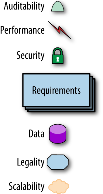
Figure 1-7. The architecture for a software system consists of both requirements and all the other architectural characteristics
As any experience in the software development world illustrates, nothing remains static. Thus, architects may design a system to meet certain criteria, but that design must survive both implementation (how can architects make sure that their design is implemented correctly) and the inevitable change driven by the software development ecosystem. What we need is an evolutionary architecture.
Building Evolutionary Architectures introduces the concept of using fitness functions to protect (and govern) architectural characteristics as change occurs over time.
We won’t go into the full details of fitness functions here. However, we will point out opportunities and examples of the approach where applicable. Note the correlation between how often fitness functions execute and the feedback they provide. You’ll see that adopting Agile engineering practices such as continuous integration, automated machine provisioning, and similar practices makes building resilient architectures easier. It also illustrates how intertwined architecture has become with engineering practices.
Operations/DevOps
However, a few years ago, several companies started experimenting with new forms of architecture that combine many operational concerns with the architecture. For example, in older-style architectures, such as ESB-driven SOA, the architecture was designed to handle things like elastic scale, greatly complicating the architecture in the process. Basically, architects were forced to defensively design around the limitations introduced because of the cost-saving measure of outsourcing operations. Thus, they built architectures that could handle scale, performance, elasticity, and a host of other capabilities internally. The side effect of that design was vastly more complex architecture.
The builders of the microservices style of architecture realized that these operational concerns are better handled by operations.
Process
Another axiom is that software architecture is mostly orthogonal to the software development process; the way that you build software (process) has little impact on the software architecture (structure).
As the previous quote from Mark observes, all architecture becomes iterative; it’s only a matter of time. Toward that end, we’re going assume a baseline of Agile methodologies throughout and call out exceptions where appropriate. For example, it is still common for many monolithic architectures to use older processes because of their age, politics, or other mitigating factors unrelated to software.
Data
A large percentage of serious application development includes external data storage, often in the form of a relational (or, increasingly, NoSQL) database. However, many
Laws of Software Architecture
While the scope of software architecture is almost impossibly broad, unifying elements do exist.
Everything in software architecture is a trade-off.
First Law of Software Architecture
Nothing exists on a nice, clean spectrum for software architects. Every decision must take into account many opposing factors.
If an architect thinks they have discovered something that isn’t a trade-off, more likely they just haven’t identified the trade-off yet.
Corollary 1
Why is more important than how.
Second Law of Software Architecture
The authors discovered the importance of this perspective when we tried keeping the results of exercises done by students during workshop as they crafted architecture solutions. Because the exercises were timed, the only artifacts we kept were the diagrams representing the topology. In other words, we captured how they solved the problem but not why the team made particular choices. An architect can look at an existing system they have no knowledge of and ascertain how the structure of the architecture works, but will struggle explaining why certain choices were made versus others.
Part I. Foundations
To understand important trade-offs in architecture, developers must understand some basic concepts and terminology concerning components, modularity, coupling, and connascence.
Chapter 2. Architectural Thinking
An architect sees things differently from a developer’s point of view, much in the same way a meteorologist might see clouds differently from an artist’s point of view.

Figure 2-1. Architectural thinking (iStockPhoto)
Architectural thinking is much more than that. It is seeing things with an architectural eye, or an architectural point of view. There are four main aspects of thinking like an architect. First, it’s understanding the difference between architecture and design and knowing how to collaborate with development teams to make architecture work. Second, it’s about having a wide breadth of technical knowledge while still maintaining a certain level of technical depth, allowing the architect to see solutions and possibilities that others do not see. Third, it’s about understanding, analyzing, and reconciling trade-offs between various solutions and technologies. Finally, it’s about understanding the importance of business drivers and how they translate to architectural concerns.
In this chapter we explore these four aspects of thinking like an architect and seeing things with an architectural eye.
Architecture Versus Design
The difference between architecture and design is often a confusing one. Where does architecture end and design begin?
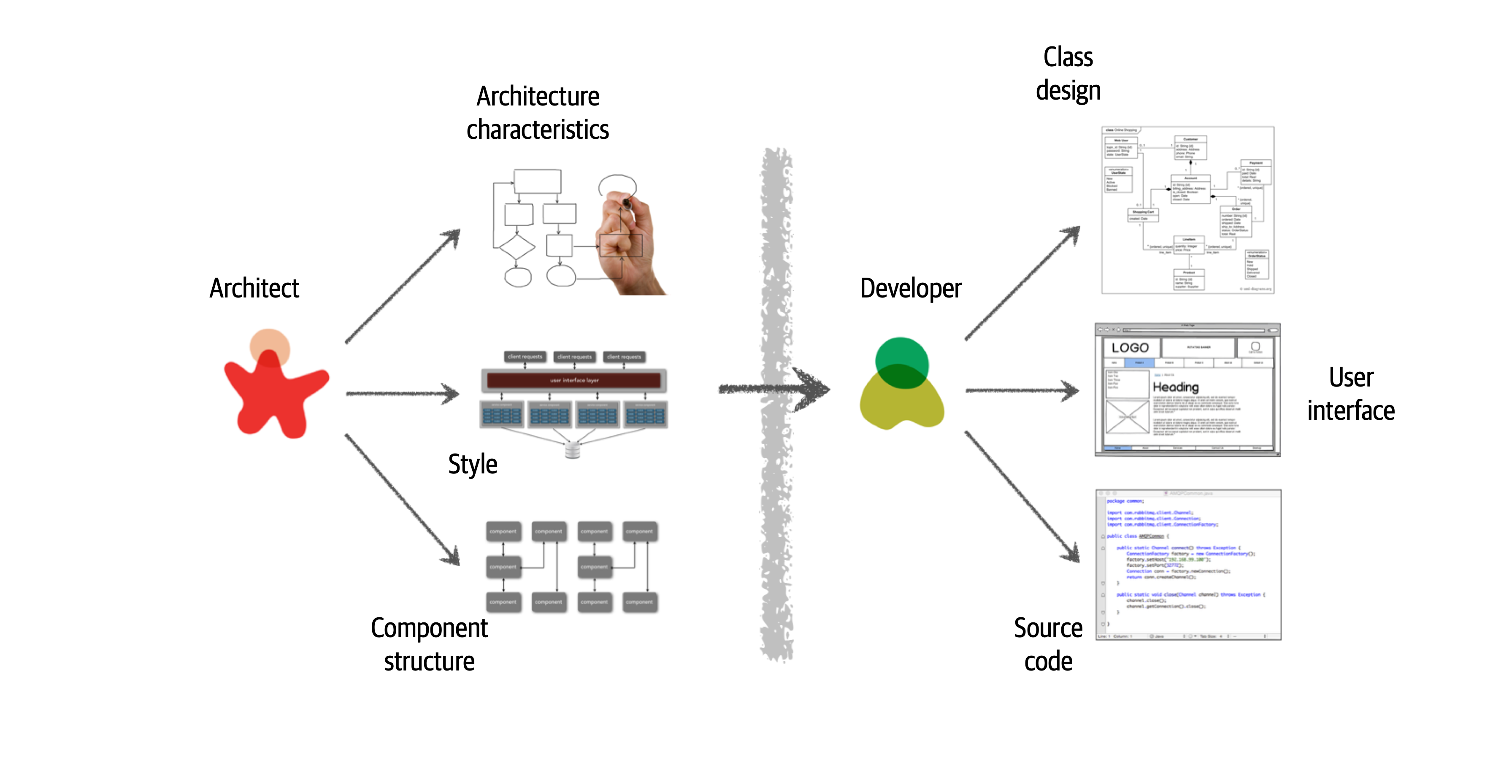
Figure 2-2. Traditional view of architecture versus design
There are several issues with the traditional responsibility model illustrated in Figure 2-2. As a matter of fact, this illustration shows exactly why architecture rarely works. Specifically, it is the unidirectional arrow passing though the virtual and physical barriers separating the architect from the developer that causes all of the problems associated with architecture. Decisions an architect makes sometimes never make it to the development teams, and decisions development teams make that change the architecture rarely get back to the architect. In this model the architect is disconnected from the development teams, and as such the architecture rarely provides what it was originally set out to do.
To make architecture work, both the physical and virtual barriers that exist between architects and developers must be broken down, thus forming a strong bidirectional relationship between architects and development teams. The architect and developer must be on the same virtual team to make this work, as depicted in Figure 2-3. Not only does this model facilitate strong bidirectional communication between architecture and development, but it also allows the architect to provide mentoring and coaching to developers on the team.
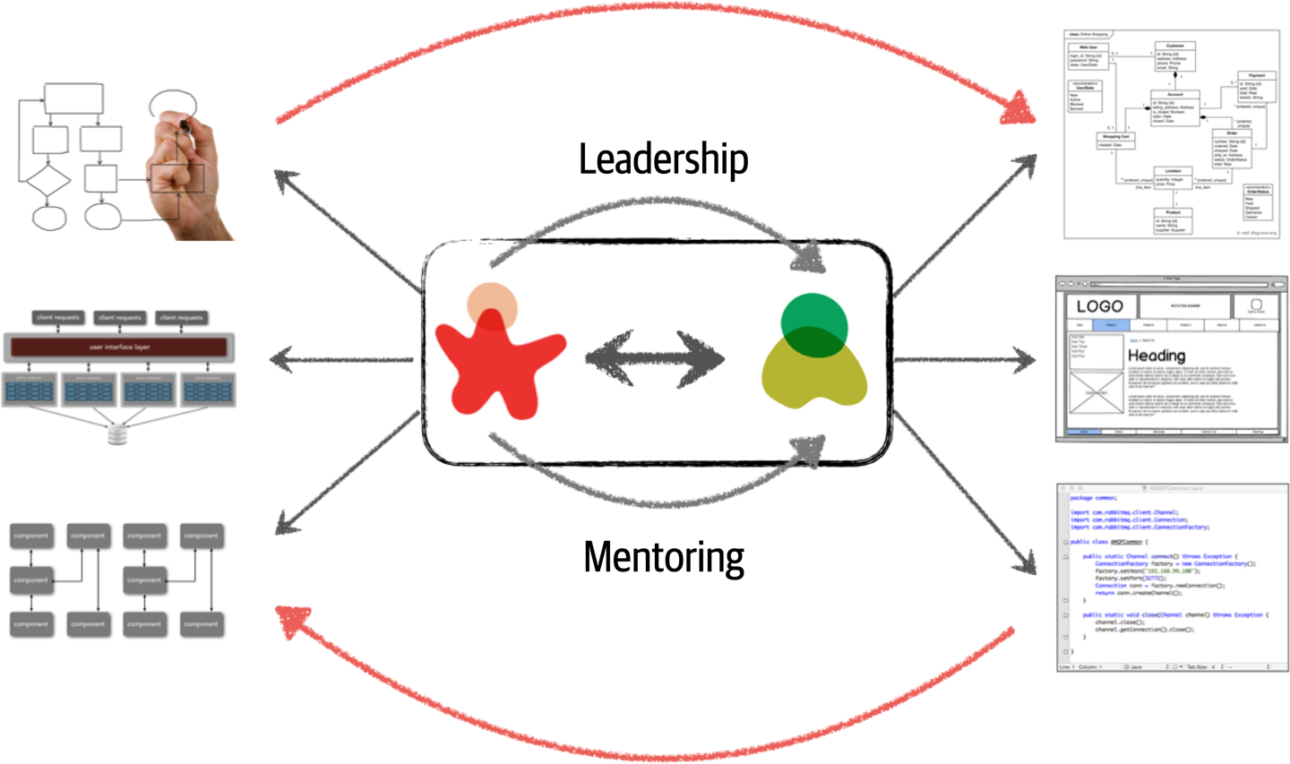
Figure 2-3. Making architecture work through collaboration
Unlike the old-school waterfall approaches to static and rigid software architecture, the architecture of today’s systems changes and evolves every iteration or phase of a project. A tight collaboration between the architect and the development team is essential for the success of any software project. So where does architecture end and design begin? It doesn’t. They are both part of the circle of life within a software project and must always be kept in synchronization
Technical Breadth
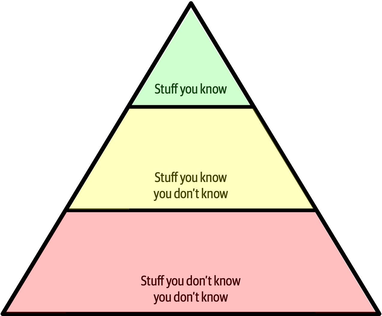
Figure 2-4. The pyramid representing all knowledge
As shown in Figure 2-4, any individual can partition all their knowledge into three sections: stuff you know, stuff you know you don’t know, and stuff you don’t know you don’t know.
Stuff you know includes the technologies, frameworks, languages, and tools a technologist uses on a daily basis to perform their job, such as knowing Java as a Java programmer. Stuff you know you don’t know includes those things a technologist knows a little about or has heard of but has little or no expertise in. A good example of this level of knowledge is the Clojure programming language. Most technologists have heard of Clojure and know it’s a programming language based on Lisp, but they can’t code in the language. Stuff you don’t know you don’t know is the largest part of the knowledge triangle and includes the entire host of technologies, tools, frameworks, and languages that would be the perfect solution to a problem a technologist is trying to solve, but the technologist doesn’t even know those things exist.
A developer’s early career focuses on expanding the top of the pyramid, to build experience and expertise. This is the ideal focus early on, because developers need more perspective, working knowledge, and hands-on experience. Expanding the top incidentally expands the middle section; as developers encounter more technologies and related artifacts, it adds to their stock of stuff you know you don’t know.
In Figure 2-5, expanding the top of the pyramid is beneficial because expertise is valued. However, the stuff you know is also the stuff you must maintain—nothing is static in the software world. If a developer becomes an expert in Ruby on Rails, that expertise won’t last if they ignore Ruby on Rails for a year or two. The things at the top of the pyramid require time investment to maintain expertise. Ultimately, the size of the top of an individual’s pyramid is their technical depth.
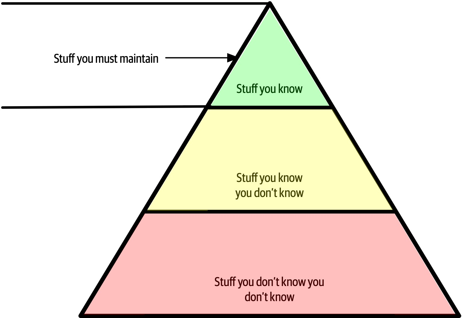
Figure 2-5. Developers must maintain expertise to retain it
However, the nature of knowledge changes as developers transition into the architect role. A large part of the value of an architect is a broad understanding of technology and how to use it to solve particular problems. For example, as an architect, it is more beneficial to know that five solutions exist for a particular problem than to have singular expertise in only one. The most important parts of the pyramid for architects are the top and middle sections; how far the middle section penetrates into the bottom section represents an architect’s technical breadth, as shown in Figure 2-6.
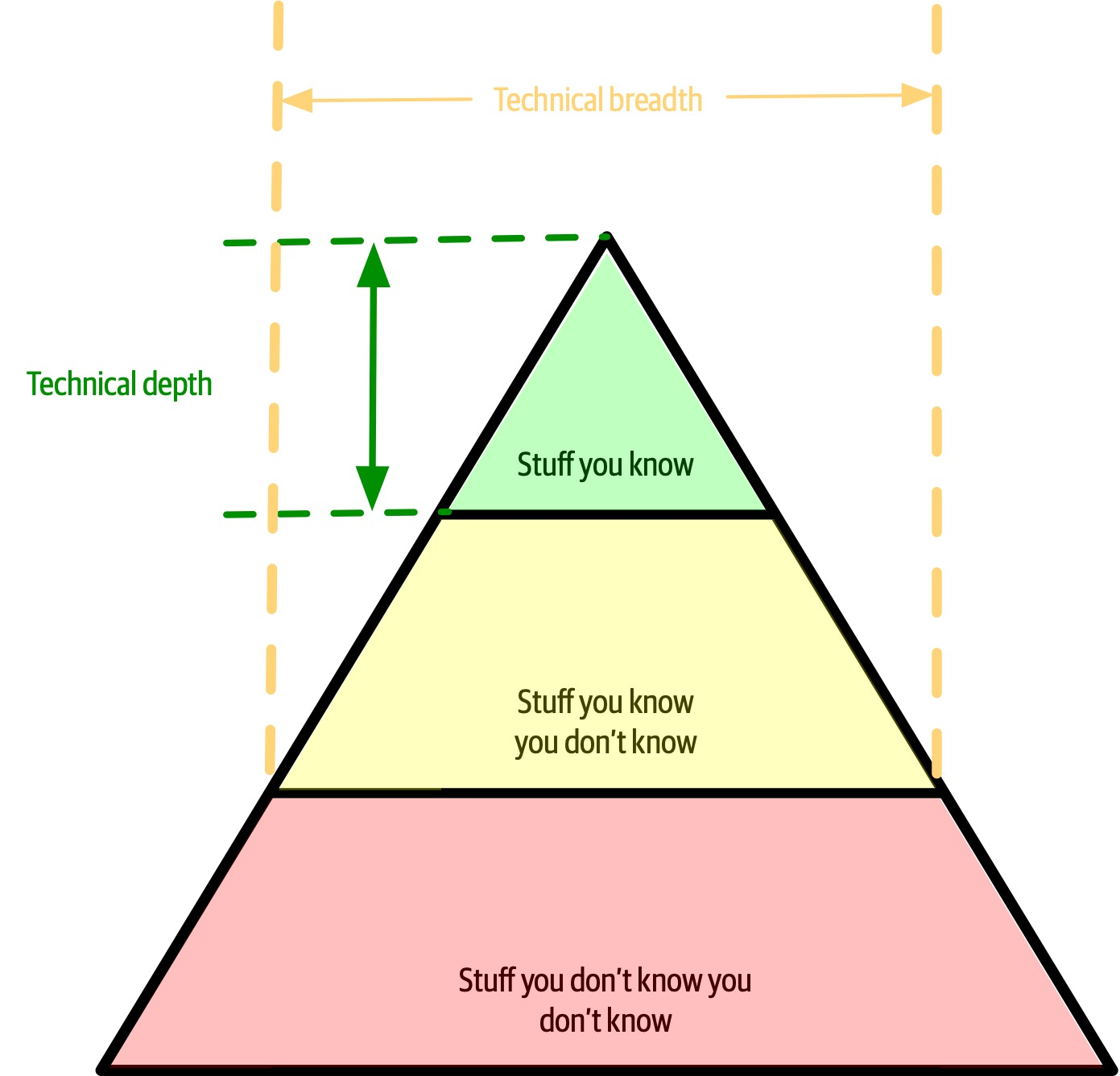
Figure 2-6. What someone knows is technical depth, and how much someone knows is technical breadth
As an architect, breadth is more important than depth. Because architects must make decisions that match capabilities to technical constraints, a broad understanding of a wide variety of solutions is valuable. Thus, for an architect, the wise course of action is to sacrifice some hard-won expertise and use that time to broaden their portfolio, as shown in Figure 2-7. As illustrated in the diagram, some areas of expertise will remain, probably in particularly enjoyable technology areas, while others usefully atrophy.
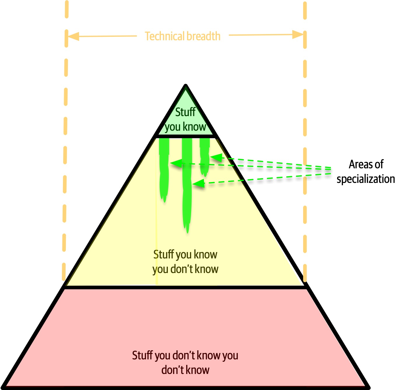
Figure 2-7. Enhanced breadth and shrinking depth for the architect role
Our knowledge pyramid illustrates how fundamentally different the role of architect compares to developer. Developers spend their whole careers honing expertise, and transitioning to the architect role means a shift in that perspective, which many individuals find difficult. This in turn leads to two common dysfunctions: first, an architect tries to maintain expertise in a wide variety of areas, succeeding in none of them and working themselves ragged in the process. Second, it manifests as stale expertise—the mistaken sensation that your outdated information is still cutting edge. We see this often in large companies where the developers who founded the company have moved into leadership roles yet still make technology decisions using ancient criteria (see “Frozen Caveman Anti-Pattern”).
Architects should focus on technical breadth so that they have a larger quiver from which to draw arrows. Developers transitioning to the architect role may have to change the way they view knowledge acquisition. Balancing their portfolio of knowledge regarding depth versus breadth is something every developer should consider throughout their career.
Analyzing Trade-Offs
Architecture is the stuff you can’t Google.
There are no right or wrong answers in architecture—only trade-offs.
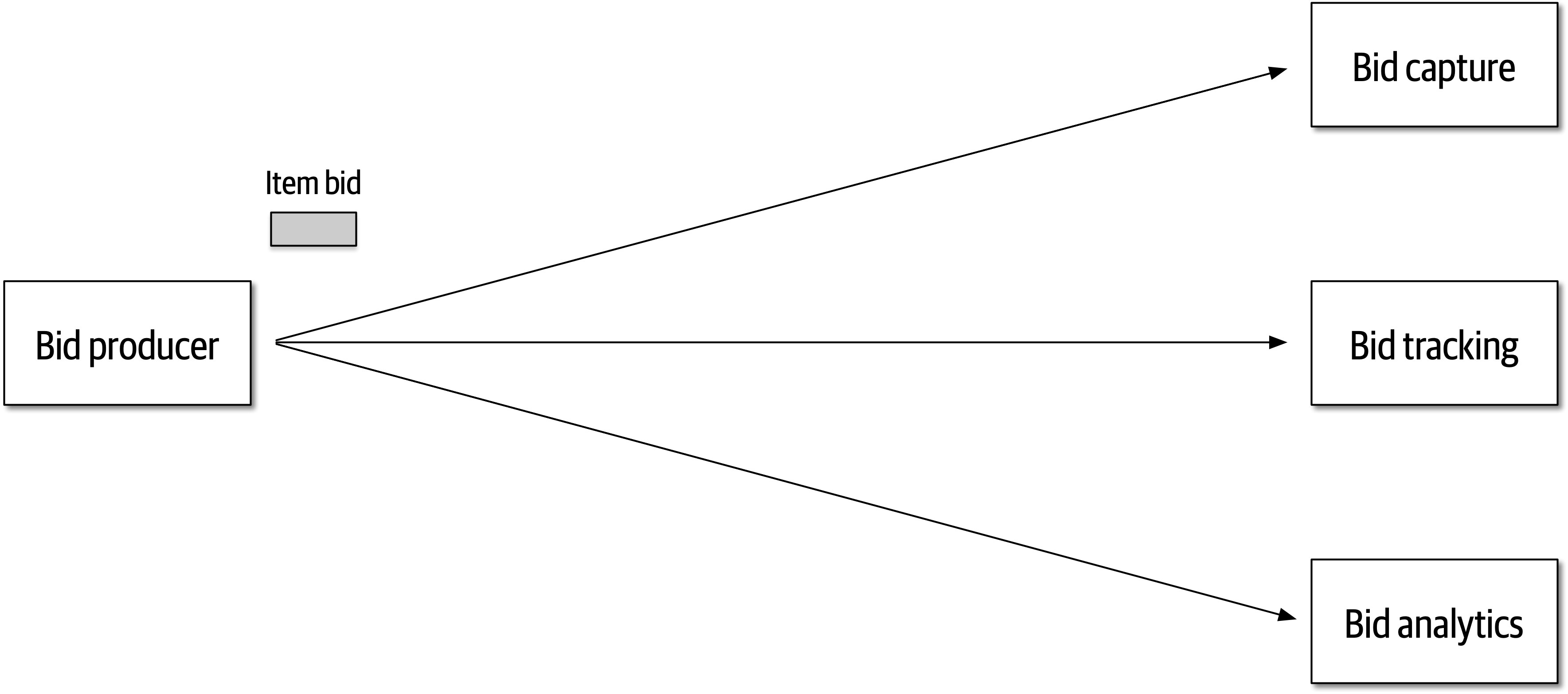
Figure 2-8. Auction system example of a trade-off—queues or topics?
The Bid Producer service generates a bid from the bidder and then sends that bid amount to the Bid Capture, Bid Tracking, and Bid Analytics services. This could be done by using queues in a point-to-point messaging fashion or by using a topic in a publish-and-subscribe messaging fashion. Which one should the architect use? You can’t Google the answer. Architectural thinking requires the architect to analyze the trade-offs associated with each option and select the best one given the specific situation.
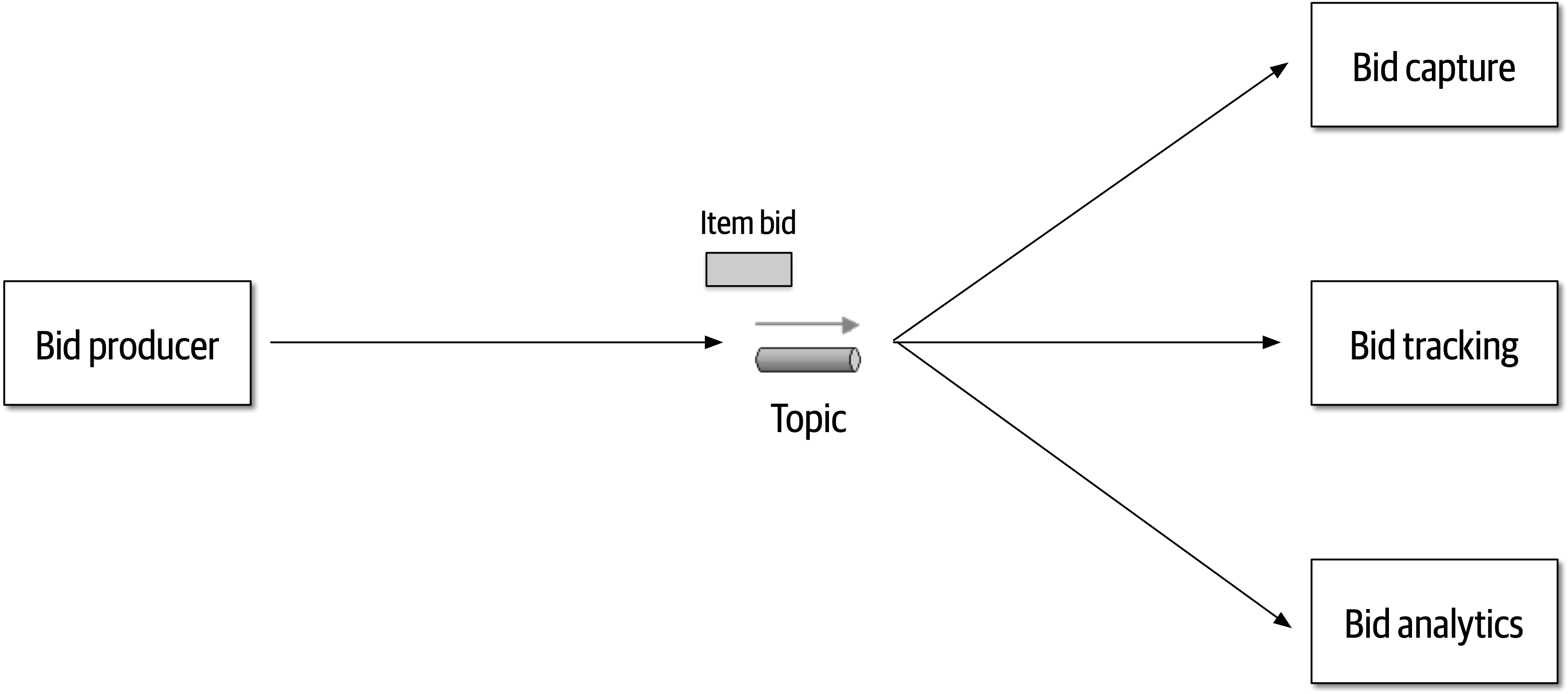
Figure 2-9. Use of a topic for communication between services
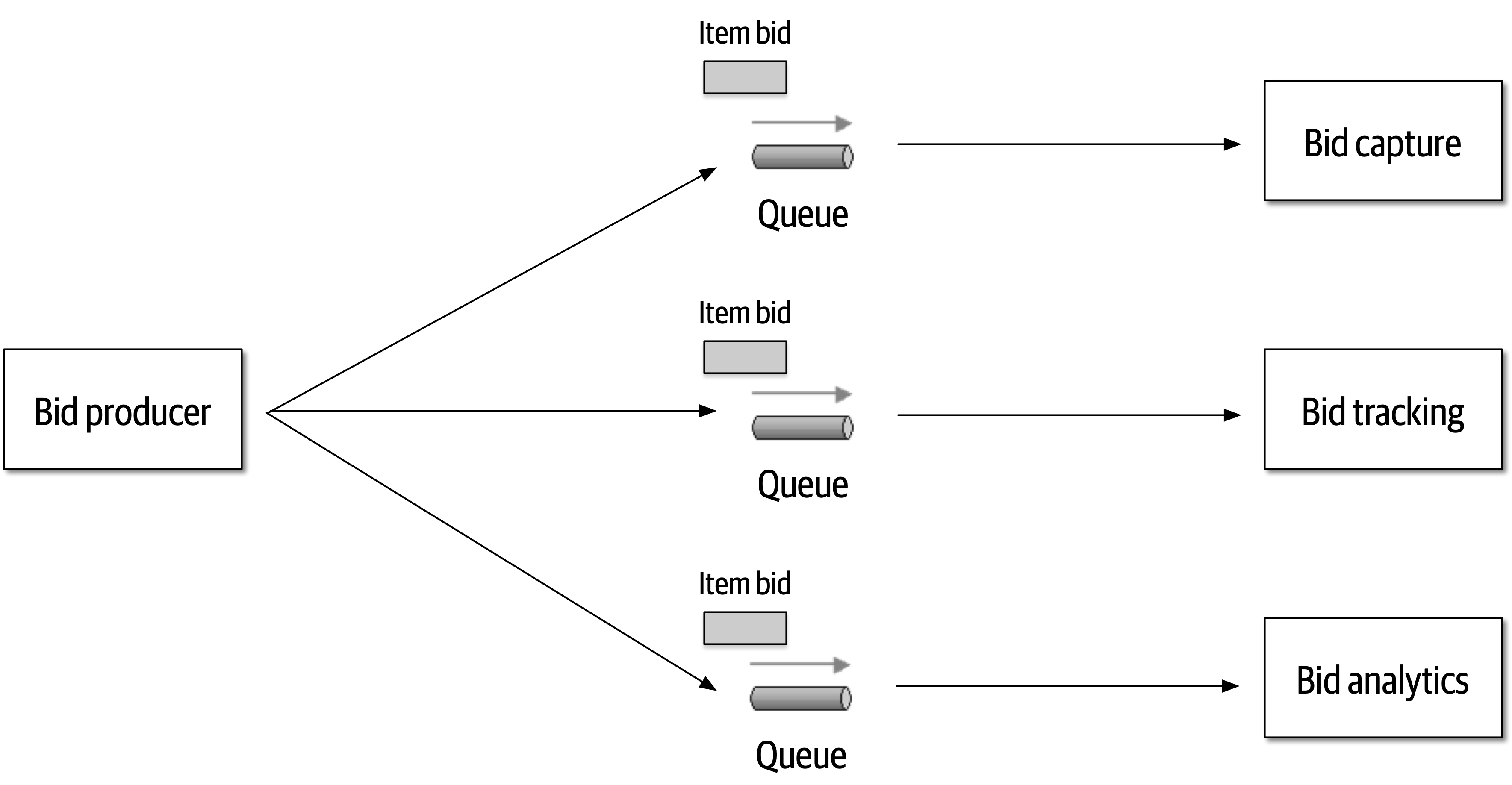
Figure 2-10. Use of queues for communication between services
The clear advantage (and seemingly obvious solution) to this problem in Figure 2-9 is that of architectural extensibility. The Bid Producer service only requires a single connection to a topic, unlike the queue solution in Figure 2-10 where the Bid Producer needs to connect to three different queues.
Bid History were to be added to this system due to the requirement to provide each bidder with a history of all the bids they made in each auction, no changes at all would be needed to the existing system. When the new Bid History service is created, it could simply subscribe to the topic already containing the bid information. In the queue option shown in Bid History service, and the Bid Producer would need to be modified to add an additional connection to the new queue. The point here is that using queues requires significant change to the system when adding new bidding functionality, whereas with the topic approach no changes are needed at all in the existing infrastructure. Also, notice that the Bid Producer is more decoupled in the topic option—the Bid Producer doesn’t know how the bidding information will be used or by which services. In the queue option the Bid Producer knows exactly how the bidding information is used (and by whom), and hence is more coupled to the system. With this analysis it seems clear that the topic approach using the publish-and-subscribe
Programmers know the benefits of everything and the trade-offs of nothing. Architects need to understand both.
In addition to the security issue, the topic solution in Figure 2-9 only supports homogeneous contracts. All services receiving the bidding data must accept the same contract and set of bidding data. In the queue option in Figure 2-10, each consumer can have its own contract specific to the data it needs. For example, suppose the new Bid History service requires the current asking price along with the bid, but no other service needs that information. In this case, the contract would need to be modified, impacting all other services using that data. In the queue model, this would be a separate channel, hence a separate contract not impacting any other service.
Another disadvantage of the topic model illustrated in Figure 2-9 is that it does not support monitoring of the number of messages in the topic and hence auto-scaling capabilities. However, with the queue option in Figure 2-10, each queue can be monitored individually, and programmatic load balancing applied to each bidding consumer so that each can be automatically scaled independency from one another. Note that this trade-off is technology specific in that the Advanced Message Queuing Protocol (AMQP) can support programmatic load balancing and monitoring because of the separation between an exchange (what the producer sends to) and a queue (what the consumer listens to).
| Topic advantages | Topic disadvantages |
|---|---|
Architectural extensibility | Data access and data security concerns |
Service decoupling | No heterogeneous contracts |
Monitoring and programmatic scalability |
The point here is that everything in software architecture has a trade-off: an advantage and disadvantage. Thinking like an architect is analyzing these trade-offs, then asking “which is more important: extensibility or security?” The decision between different solutions will always depend on the business drivers, environment, and a host of other factors.
Understanding Business Drivers
Thinking like an architect is understanding the business drivers that are required for the success of the system and translating those requirements into architecture characteristics (such as scalability, performance, and availability).
Balancing Architecture and Hands-On Coding
One of the difficult tasks an architect faces is how to balance hands-on coding with software architecture.
The first tip in striving for a balance between hands-on coding and being a software
One way to avoid the bottleneck trap as an effective software architect is to delegate the critical path and framework code to others on the development team and then focus on coding a piece of business functionality (a service or a screen) one to three iterations down the road. Three positive things happen by doing this. First, the architect is gaining hands-on experience writing production code while no longer becoming a bottleneck on the team. Second, the critical path and framework code is distributed to the development team (where it belongs), giving them ownership and a better understanding of the harder parts of the system. Third, and perhaps most important, the architect is writing the same business-related source code as the development team and is therefore better able to identify with the development team in terms of the pain they might be going through with processes, procedures, and the development environment.
Suppose, however, that the architect is not able to develop code with the development team. How can a software architect still remain hands-on and maintain some level of technical depth? There are four basic ways an architect can still remain hands-on at work without having to “practice coding from home” (although we recommend practicing coding at home as well).
Our advice when doing proof-of-concept work is that, whenever possible, the architect should write the best production-quality code they can. We recommend this practice for two reasons. First, quite often, throwaway proof-of-concept code goes into the source code repository and becomes the reference architecture or guiding example for others to follow. The last thing an architect would want is for their throwaway, sloppy code to be a representation of their typical work. The second reason is that by writing production-quality proof-of-concept code, the architect gets practice writing quality, well-structured code rather than continually developing bad coding practices.
A final technique to remain hands-on as an architect is to do frequent code reviews.
Chapter 3. Modularity
First, we want to untangle some common terms used and overused in discussions about architecture surrounding modularity and provide definitions for use throughout the book.
95% of the words [about software architecture] are spent extolling the benefits of “modularity” and that little, if anything, is said about how to achieve it.
Glenford J. Myers (1978)
Different platforms offer different reuse mechanisms for code, but all support some way of grouping related code together into modules. While this concept is universal in software architecture, it has proven slippery to define. A casual internet search yields dozens of definitions, with no consistency (and some contradictions). As you can see from the quote from Myers, this isn’t a new problem. However, because no recognized definition exists, we must jump into the fray and provide our own definitions for the sake of consistency throughout the book.
Understanding modularity and its many incarnations in the development platform of choice is critical for architects. Many of the tools we have to analyze architecture (such as metrics, fitness functions, and visualizations) rely on these modularity concepts. Modularity is an organizing principle. If an architect designs a system without paying attention to how the pieces wire together, they end up creating a system that presents myriad difficulties. To use a physics analogy, software systems model complex systems, which tend toward entropy (or disorder). Energy must be added to a physical system to preserve order. The same is true for software systems: architects must constantly expend energy to ensure good structural soundness, which won’t happen by accident.
Definition
package in Java, namespace in .NET, and so on). Developers typically use modules as a way to group related code together. For example, the com.mycompany.customer package in Java should contain things related to customers.Architects must be aware of how developers package things because it has important implications in architecture. For example, if several packages are tightly coupled together, reusing one of them for related work becomes more difficult.
For discussions about architecture, we use modularity as a general term to denote a related grouping of code: classes, functions, or any other grouping. This doesn’t imply a physical separation, merely a logical one; the difference is sometimes important. For example, lumping a large number of classes together in a monolithic application may make sense from a convenience standpoint. However, when it comes time to restructure the architecture, the coupling encouraged by loose partitioning becomes an impediment to breaking the monolith apart. Thus, it is useful to talk about modularity as a concept separate from the physical separation forced or implied by a particular platform.
Measuring Modularity
Cohesion
Cohesion refers to what extent the parts of a module should be contained within the same module. In other words, it is a measure of how related the parts are to one another. Ideally, a cohesive module is one where all the parts should be packaged together, because breaking them into smaller pieces would require coupling the parts together via calls between modules to achieve useful results.
Attempting to divide a cohesive module would only result in increased coupling and decreased readability.
Larry Constantine
Computer scientists have defined a range of cohesion measures, listed here from best to worst:
- Functional cohesion
-
Every part of the module is related to the other, and the module contains everything essential to function.
- Sequential cohesion
-
Two modules interact, where one outputs data that becomes the input for the other.
- Communicational cohesion
-
Two modules form a communication chain, where each operates on information and/or contributes to some output. For example, add a record to the database and generate an email based on that information.
- Procedural cohesion
-
Two modules must execute code in a particular order.
- Temporal cohesion
- Modules are related based on timing dependencies.For example, many systems have a list of seemingly unrelated things that must be initialized at system startup; these different tasks are temporally cohesive.
- Logical cohesion
-
The data within modules is related logically but not functionally. For example, consider a module that converts information from text, serialized objects, or streams. Operations are related, but the functions are quite different. A common example of this type of cohesion exists in virtually every Java project in the form of the
StringUtilspackage: a group of static methods that operate onStringbut are otherwise unrelated. - Coincidental cohesion
-
Elements in a module are not related other than being in the same source file; this represents the most negative form of cohesion.
Despite having seven variants listed, cohesion is a less precise metric than coupling. Often, the degree of cohesiveness of a particular module is at the discretion of a particular architect. For example, consider this module definition:
Customer Maintenance-
-
add customer -
update customer -
get customer -
notify customer -
get customer orders -
cancel customer orders
-
Should the last two entries reside in this module or should the developer create two separate modules, such as:
Customer Maintenance-
-
add customer -
update customer -
get customer -
notify customer
-
Order Maintenance-
-
get customer orders -
cancel customer orders
-
Which is the correct structure? As always, it depends:
-
Are those the only two operations for
Order Maintenance? If so, it may make sense to collapse those operations back intoCustomer Maintenance. -
Is
Customer Maintenanceexpected to grow much larger, encouraging developers to look for opportunities to extract behavior? -
Does
Order Maintenancerequire so much knowledge ofCustomerinformation that separating the two modules would require a high degree of coupling to make it functional? This relates back to the Larry Constantine quote.
These questions represent the kind of trade-off analysis at the heart of the job of a software architect.
The Chidamber and Kemerer Lack of Cohesion in Methods (LCOM) metric measures the structural cohesion of a module, typically a component. The initial version appears in Equation 3-1.
Equation 3-1. LCOM, version 1
P increases by one for any method that doesn’t access a particular shared field and Q decreases by one for methods that do share a particular shared field. The authors sympathize with those who don’t understand this formulation. Worse, it has gradually gotten more elaborate over time. The second variation introduced in 1996 (thus the name LCOM96B) appears in Equation 3-2.
Equation 3-2. LCOM 96b
We wont bother untangling the variables and operators in Equation 3-2 because the following written explanation is clearer. Basically, the LCOM metric exposes incidental coupling within classes. Here’s a better definition of LCOM:
- LCOM
-
The sum of sets of methods not shared via sharing fields
Consider a class with private fields a and b. Many of the methods only access a, and many other methods only access b. The sum of the sets of methods not shared via sharing fields (a and b) is high; therefore, this class reports a high LCOM score, indicating that it scores high in lack of cohesion in methods. Consider the three classes shown in Figure 3-1.
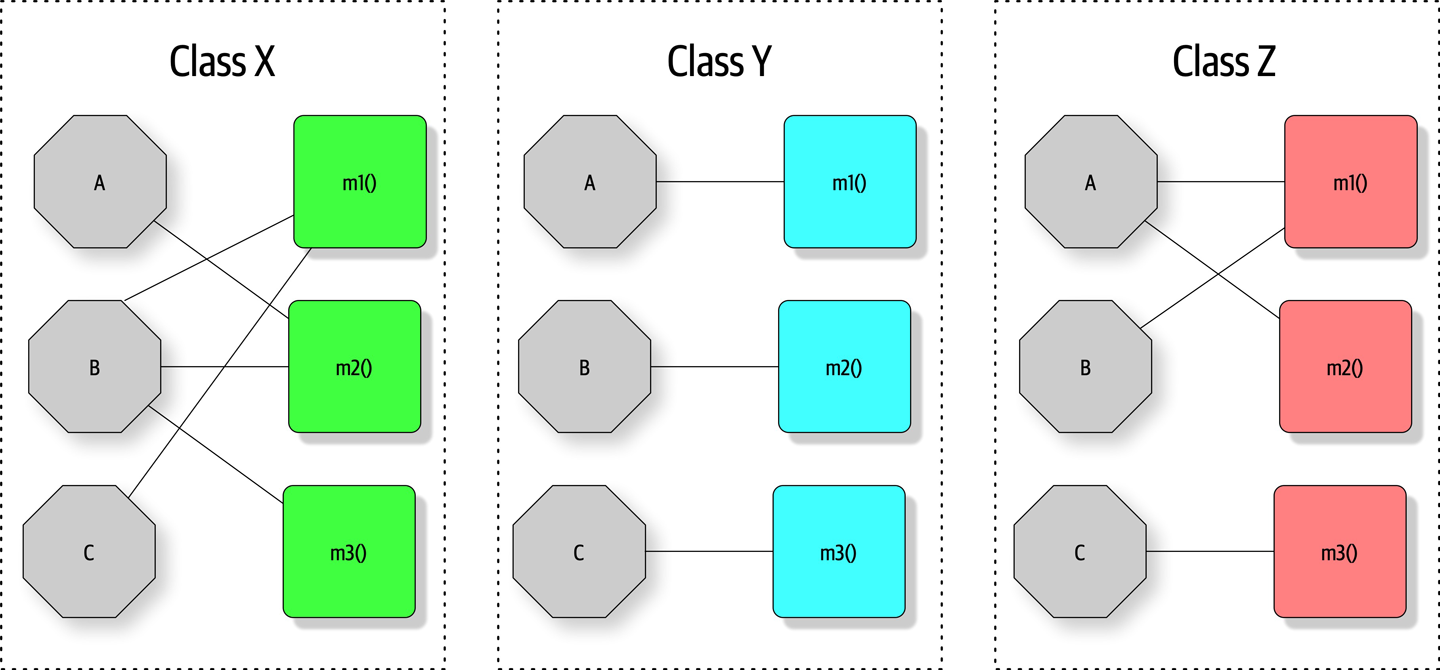
Figure 3-1. Illustration of the LCOM metric, where fields are octagons and methods are squares
In Figure 3-1, fields appear as single letters and methods appear as blocks. In Class X, the LCOM score is low, indicating good structural cohesion. Class Y, however, lacks cohesion; each of the field/method pairs in Class Y could appear in its own class without affecting behavior. Class Z shows mixed cohesion, where developers could refactor the last field/method combination into its own class.
The LCOM metric is useful to architects who are analyzing code bases in order to move from one architectural style to another. One of the common headaches when moving architectures are shared utility classes. Using the LCOM metric can help architects find classes that are incidentally coupled and should never have been a single class to begin with.
Many software metrics have serious deficiencies, and LCOM is not immune. All this metric can find is structural lack of cohesion; it has no way to determine logically if particular pieces fit together. This reflects back on our Second Law of Software Architecture: prefer why over how.
Coupling
Fortunately, we have better tools to analyze coupling in code bases, based in part on graph theory: because the method calls and returns form a call graph, analysis based on mathematics becomes possible. In 1979, Edward Yourdon and and Larry Constantine published Structured Design: Fundamentals of a Discipline of Computer Program and Systems Design (Prentice-Hall), defining many core concepts, including the metrics afferent and efferent coupling. Afferent coupling measures the number of incoming connections to a code artifact (component, class, function, and so on). Efferent coupling measures the outgoing connections to other code artifacts. For virtually every platform tools exist that allow architects to analyze the coupling characteristics of code in order to assist in restructuring, migrating, or understanding a code base.
Abstractness, Instability, and Distance from the Main Sequence
While the raw value of component coupling has value to architects, several other derived metrics allow a deeper evaluation. These metrics were created by Robert Martin for a C++ book, but are widely applicable to other object-oriented languages.
Abstractness is the ratio of abstract artifacts (abstract classes, interfaces, and so on) to concrete artifacts (implementation). It represents a measure of abstractness versus implementation. For example, consider a code base with no abstractions, just a huge, single function of code (as in a single main() method). The flip side is a code base with too many abstractions, making it difficult for developers to understand how things wire together (for example, it takes developers a while to figure out what to do with an AbstractSingletonProxyFactoryBean).
The formula for abstractness appears in Equation 3-3.
Equation 3-3. Abstractness
In the equation, represents abstract elements (interfaces or abstract classes) with the module, and represents concrete elements (nonabstract classes). This metric looks for the same criteria. The easiest way to visualize this metric: consider an application with 5,000 lines of code, all in one main() method. The abstractness numerator is 1, while the denominator is 5,000, yielding an abstractness of almost 0. Thus, this metric measures the ratio of abstractions in your code.
Architects calculate abstractness by calculating the ratio of the sum of abstract artifacts to the sum of the concrete ones.
Another derived metric, instability, is defined as the ratio of efferent coupling to the sum of both efferent and afferent coupling, shown in Equation 3-4.
Equation 3-4. Instability
In the equation, represents efferent (or outgoing) coupling, and represents afferent (or incoming) coupling.
The instability metric determines the volatility of a code base. A code base that exhibits high degrees of instability breaks more easily when changed because of high coupling. For example, if a class calls to many other classes to delegate work, the calling class shows high susceptibility to breakage if one or more of the called methods change.
Distance from the Main Sequence
One of the few holistic metrics architects have for architectural structure is distance from the main sequence, a derived metric based on instability and abstractness, shown in Equation 3-5.
Equation 3-5. Distance from the main sequence
In the equation, A = abstractness and I = instability.
Note that both abstractness and instability are ratios, meaning their result will always fall between 0 and 1. Thus, when graphing the relationship, we see the graph in Figure 3-2.
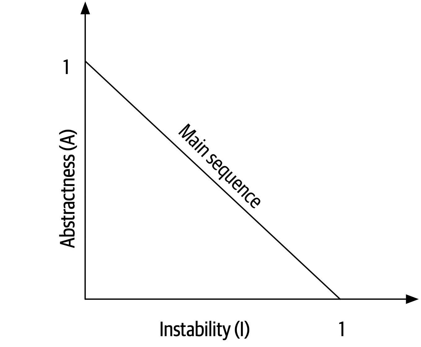
Figure 3-2. The main sequence defines the ideal relationship between abstractness and instability
The distance metric imagines an ideal relationship between abstractness and instability; classes that fall near this idealized line exhibit a healthy mixture of these two competing concerns. For example, graphing a particular class allows developers to calculate the distance from the main sequence metric, illustrated in Figure 3-3.
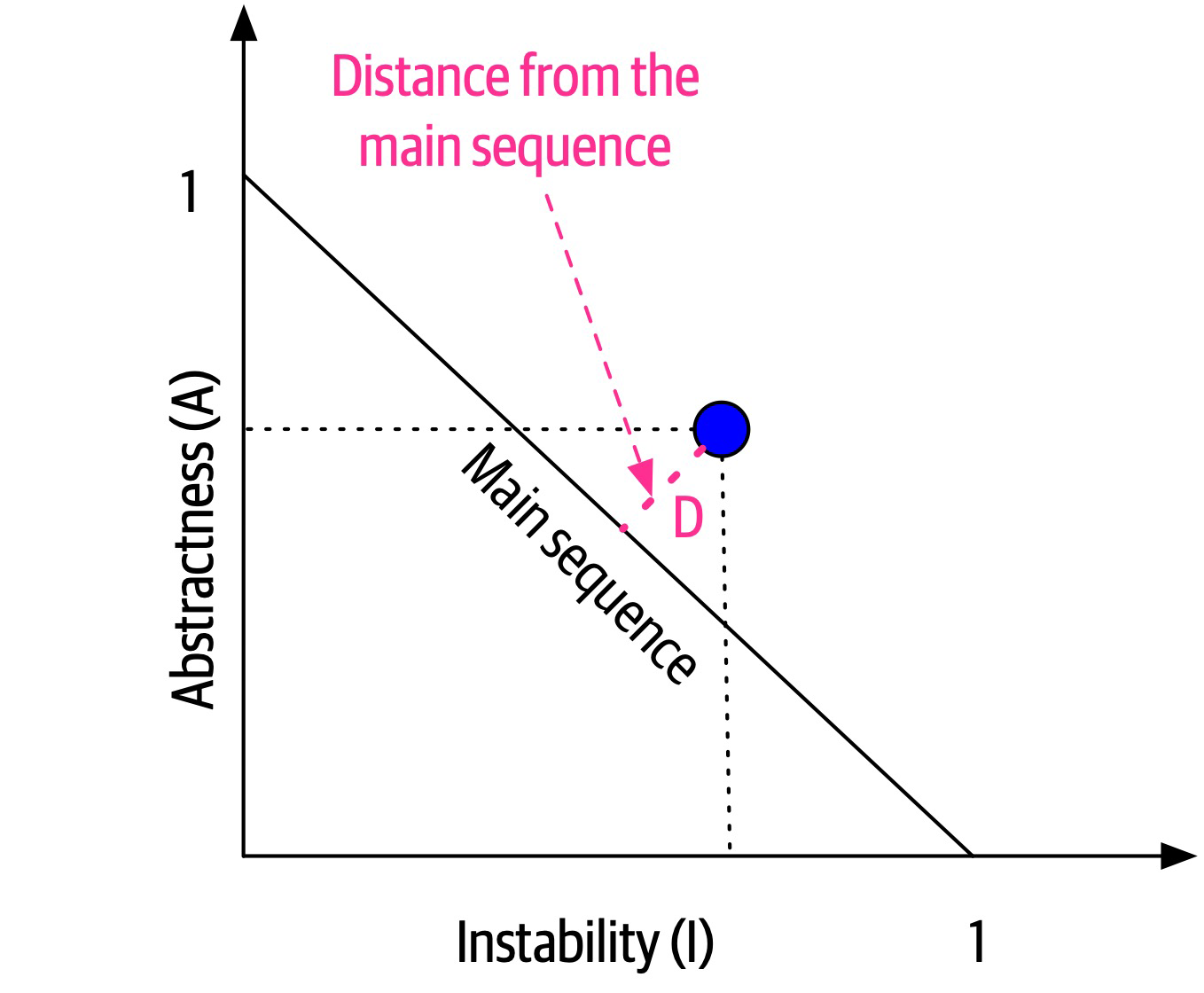
Figure 3-3. Normalized distance from the main sequence for a particular class
In Figure 3-3, developers graph the candidate class, then measure the distance from the idealized line. The closer to the line, the better balanced the class. Classes that fall too far into the upper-righthand corner enter into what architects call the zone of uselessness: code that is too abstract becomes difficult to use. Conversely, code that falls into the lower-lefthand corner enter the zone of pain: code with too much implementation and not enough abstraction becomes brittle and hard to maintain, illustrated in Figure 3-4.
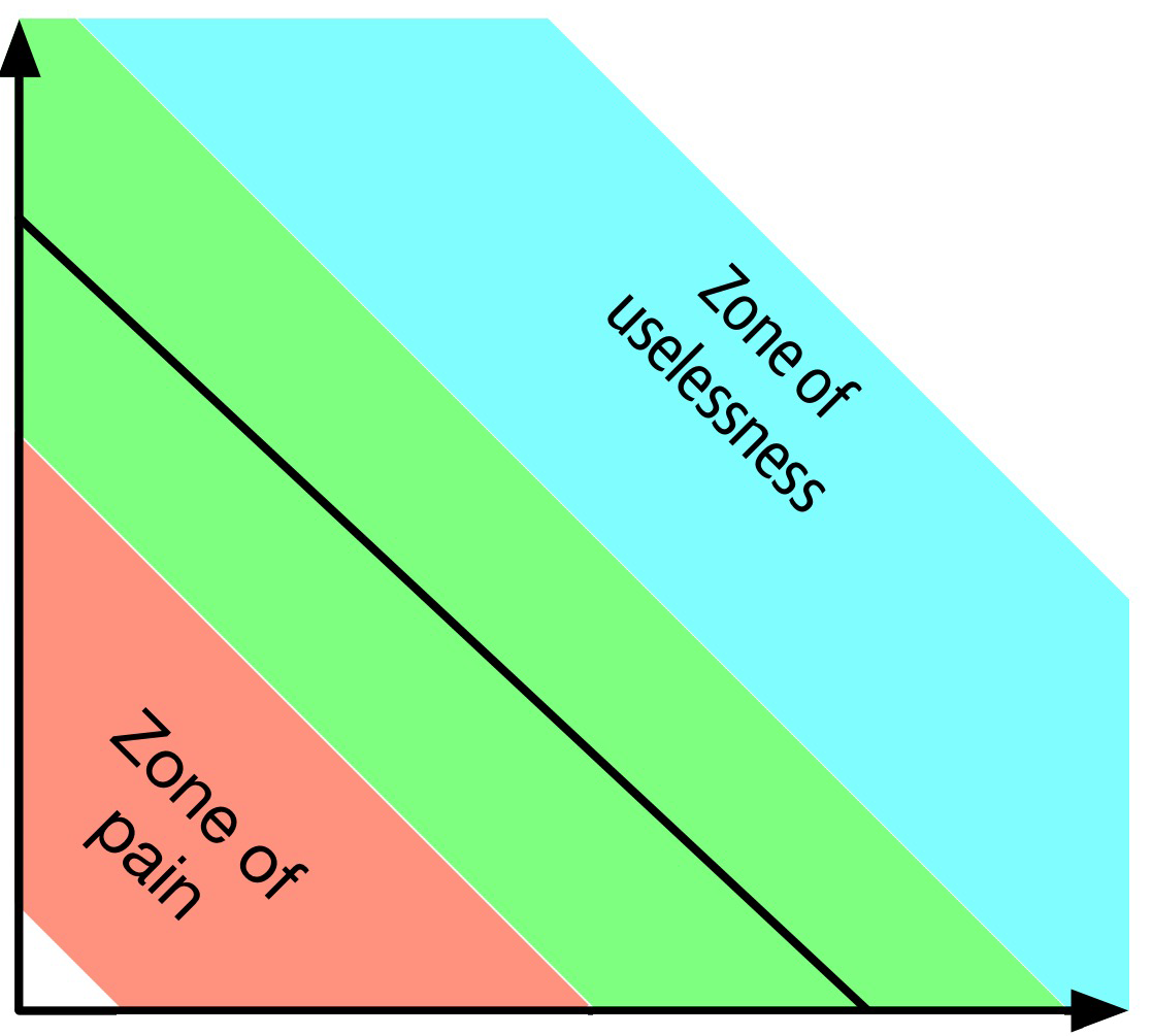
Figure 3-4. Zones of Uselessness and Pain
Tools exist in many platforms to provide these measures, which assist architects when analyzing code bases because of unfamiliarity, migration, or technical debt assessment.
Notice that the previously mentioned book by Edward Yourdon and and Larry Constantine (Structured Design: Fundamentals of a Discipline of Computer Program and Systems Design) predates the popularity of object-oriented languages, focusing instead on structured programming constructs, such as functions (not methods). It also defined other types of coupling that we do not cover here because they have been supplanted by connascence.
Connascence
In 1996, Meilir Page-Jones published What Every Programmer Should Know About Object-Oriented Design (Dorset House), refining the afferent and efferent coupling metrics and recasting them to object-oriented languages with a concept he named connascence. Here’s how he defined the term:
Two components are connascent if a change in one would require the other to be modified in order to maintain the overall correctness of the system.
Meilir Page-Jones
He developed two types of connascence: static and dynamic.
Static connascence
Static connascence refers to source-code-level coupling (as opposed to execution-time coupling, covered in “Dynamic connascence”); it is a refinement of the afferent and efferent couplings defined by Structured Design. In other words, architects view the following types of static connascence as the degree to which something is coupled, either afferently or efferently:
- Connascence of Name (CoN)
-
Multiple components must agree on the name of an entity.
Names of methods represents the most common way that code bases are coupled and the most desirable, especially in light of modern refactoring tools that make system-wide name changes trivial.
- Connascence of Type (CoT)
-
Multiple components must agree on the type of an entity.
This type of connascence refers to the common facility in many statically typed languages to limit variables and parameters to specific types. However, this capability isn’t purely a language feature—some dynamically typed languages offer selective typing, notably Clojure and Clojure Spec.
- Connascence of Meaning (CoM) or Connascence of Convention (CoC)
-
Multiple components must agree on the meaning of particular values.
The most common obvious case for this type of connascence in code bases is hard-coded numbers rather than constants. For example, it is common in some languages to consider defining somewhere
int TRUE = 1; int FALSE = 0. Imagine the problems if someone flips those values. - Connascence of Position (CoP)
-
Multiple entities must agree on the order of values.
This is an issue with parameter values for method and function calls even in languages that feature static typing. For example, if a developer creates a method
void updateSeat(String name, String seatLocation)and calls it with the valuesupdateSeat("14D", "Ford, N"), the semantics aren’t correct even if the types are. - Connascence of Algorithm (CoA)
-
Multiple components must agree on a particular algorithm.
A common case for this type of connascence occurs when a developer defines a security hashing algorithm that must run on both the server and client and produce identical results to authenticate the user. Obviously, this represents a high form of coupling—if either algorithm changes any details, the handshake will no longer work.
Dynamic connascence
The other type of connascence Page-Jones defined was dynamic connascence, which analyses calls at runtime. The following is a description of the different types of dynamic connascence:
- Connascence of Execution (CoE)
-
The order of execution of multiple components is important.
Consider this code:
email=newEmail();email.setRecipient("foo@example.com");email.setSender("me@me.com");email.send();email.setSubject("whoops");It won’t work correctly because certain properties must be set in order.
- Connascence of Timing (CoT)
-
The timing of the execution of multiple components is important.
The common case for this type of connascence is a race condition caused by two threads executing at the same time, affecting the outcome of the joint operation.
- Connascence of Values (CoV)
-
Occurs when several values relate on one another and must change together.
Consider the case where a developer has defined a rectangle as four points, representing the corners. To maintain the integrity of the data structure, the developer cannot randomly change one of points without considering the impact on the other points.
The more common and problematic case involves transactions, especially in distributed systems. When an architect designs a system with separate databases, yet needs to update a single value across all of the databases, all the values must change together or not at all.
- Connascence of Identity (CoI)
-
Occurs when several values relate on one another and must change together.
The common example of this type of connascence involves two independent components that must share and update a common data structure, such as a distributed queue.
Architects have a harder time determining dynamic connascence because we lack tools to analyze runtime calls as effectively as we can analyze the call graph.
Connascence properties
Connascence is an analysis tool for architect and developers, and some properties of connascence help developers use it wisely. The following is a description of each of these connascence properties:
- Strength
-
Architects determine the strength of connascence by the ease with which a developer can refactor that type of coupling; different types of connascence are demonstrably more desirable, as shown in Figure 3-5. Architects and developers can improve the coupling characteristics of their code base by refactoring toward better types of connascence.
Architects should prefer static connascence to dynamic because developers can determine it by simple source code analysis, and modern tools make it trivial to improve static connascence. For example, consider the case of connascence of meaning, which developers can improve by refactoring to connascence of name by creating a named constant rather than a magic value.
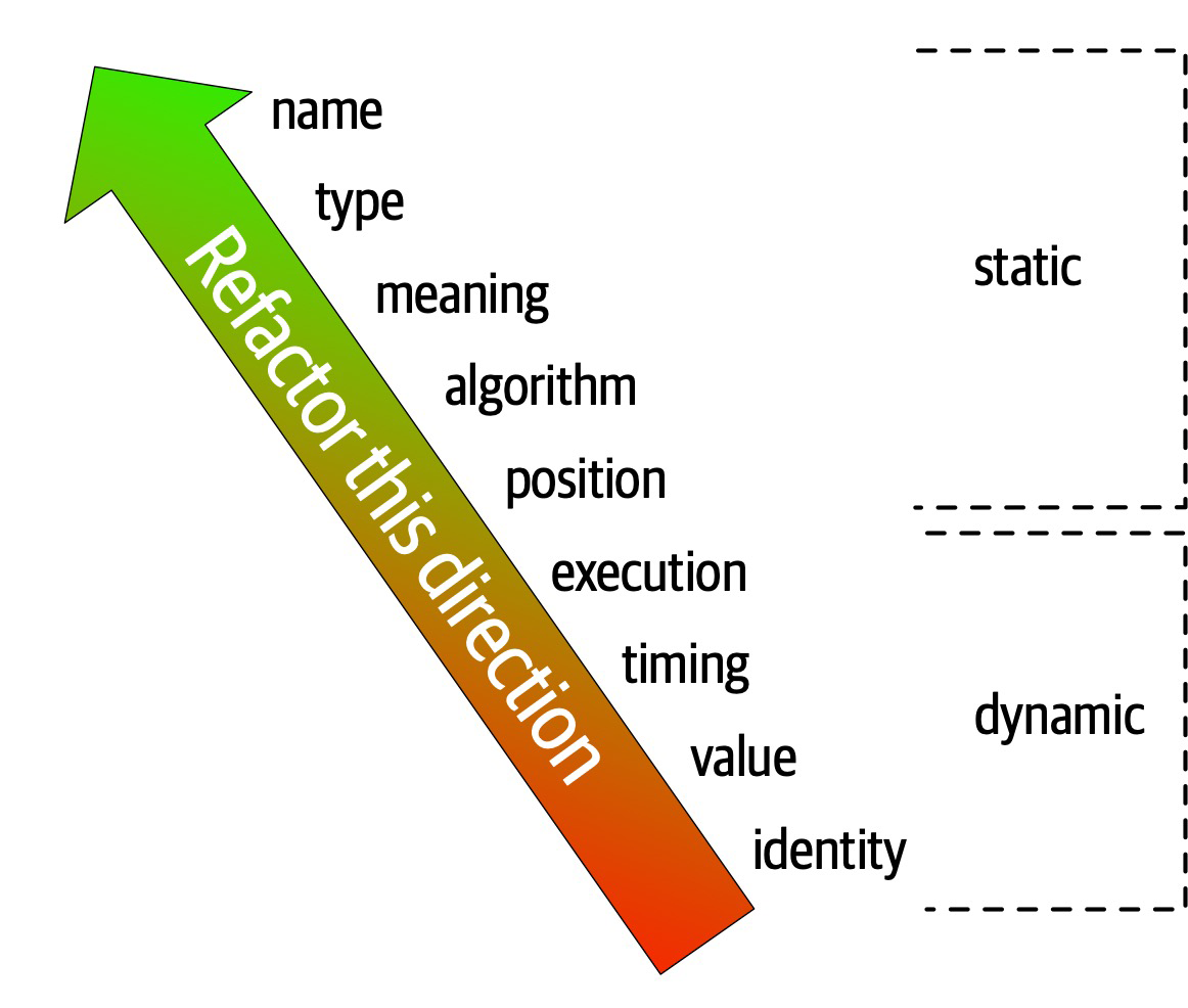
Figure 3-5. The strength on connascence provides a good refactoring guide
- Locality
-
The locality of connascence measures how proximal the modules are to each other in the code base. Proximal code (in the same module) typically has more and higher forms of connascence than more separated code (in separate modules or code bases). In other words, forms of connascence that indicate poor coupling when far apart are fine when closer together. For example, if two classes in the same component have connascence of meaning, it is less damaging to the code base than if two components have the same form of connascence.
Developers must consider strength and locality together. Stronger forms of connascence found within the same module represent less code smell than the same connascence spread apart.
- Degree
-
The degree of connascence relates to the size of its impact—does it impact a few classes or many? Lesser degrees of connascence damage code bases less. In other words, having high dynamic connascence isn’t terrible if you only have a few modules. However, code bases tend to grow, making a small problem correspondingly bigger.
Page-Jones offers three guidelines for using connascence to improve systems modularity:
-
Minimize overall connascence by breaking the system into encapsulated elements
-
Minimize any remaining connascence that crosses encapsulation boundaries
-
Maximize the connascence within encapsulation boundaries
The legendary software architecture innovator Jim Weirich repopularized the concept of connascence and offers two great pieces of advice:
Rule of Degree: convert strong forms of connascence into weaker forms of connascence
Rule of Locality: as the distance between software elements increases, use weaker forms of connascence
Unifying Coupling and Connascence Metrics
So far, we’ve discussed both coupling and connascence, measures from different eras and with different targets. However, from an architect’s point of view, these two views overlap. What Page-Jones identifies as static connascence represents degrees of either incoming or outgoing coupling. Structured programming only cares about in or out, whereas connascence cares about how things are coupled together. To help visualize the overlap in concepts, consider Figure 3-6.
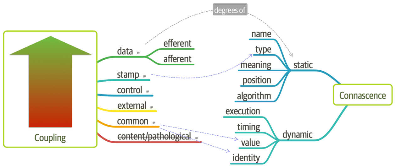
Figure 3-6. Unifying coupling and connascence
In Figure 3-6, the structured programming coupling concepts appear on the left, while the connascence characteristics appear on the right. What structured programming called data coupling (method calls), connascence provides advice for how that coupling should manifest. Structured programming didn’t really address the areas covered by dynamic connascence; we encapsulate that concept shortly in “Architectural Quanta and Granularity”.
The problems with 1990s connascence
Several problems exist for architects when applying these useful metrics for analyzing and designing systems. First, these measures look at details at a low level of code, focusing on code quality and hygiene than necessarily architectural structure. Architects tend to care more about how modules are coupled rather than the degree of coupling. For example, an architect cares about synchronous versus asynchronous communication, and doesn’t care so much about how that’s implemented.
The second problem with connascence lies with the fact that it doesn’t really address a fundamental decision that many modern architects must make—synchronous or asynchronous communication in distributed architectures like microservices? Referring back to the First Law of Software Architecture, everything is a trade-off. After we discuss the scope of architecture characteristics in Chapter 7, we’ll introduce new ways to think about modern connascence.
From Modules to Components
We use the term module throughout as a generic name for a bundling of related code. However, most platforms support some form of component, one of the key building blocks for software architects. The concept and corresponding analysis of the logical or physical separation has existed since the earliest days of computer science. Yet, with all the writing and thinking about components and separation, developers and architects still struggle with achieving good outcomes.
Chapter 4. Architecture Characteristics Defined
A company decides to solve a particular problem using software, so it gathers a list of requirements for that system.
Figure 4-1. A software solution consists of both domain requirements and architectural characteristics
Architects may collaborate on defining the domain or business requirements, but one key responsibility entails defining, discovering, and otherwise analyzing all the things the software must do that isn’t directly related to the domain functionality: architectural characteristics.
What distinguishes software architecture from coding and design? Many things, including the role that architects have in defining architectural characteristics, the important aspects of the system independent of the problem domain. Many organizations describe these features of software with a variety of terms, including nonfunctional requirements, but we dislike that term because it is self-denigrating. Architects created that term to distinguish architecture characteristics from functional requirements, but naming something nonfunctional has a negative impact from a language standpoint: how can teams be convinced to pay enough attention to something “nonfunctional”? Another popular term is quality attributes, which we dislike because it implies after-the-fact quality assessment rather than design. We prefer architecture characteristics because it describes concerns critical to the success of the architecture, and therefore the system as a whole, without discounting its importance.
An architecture characteristic meets three criteria:
-
Specifies a nondomain design consideration
-
Influences some structural aspect of the design
-
Is critical or important to application success
These interlocking parts of our definition are illustrated in Figure 4-2.
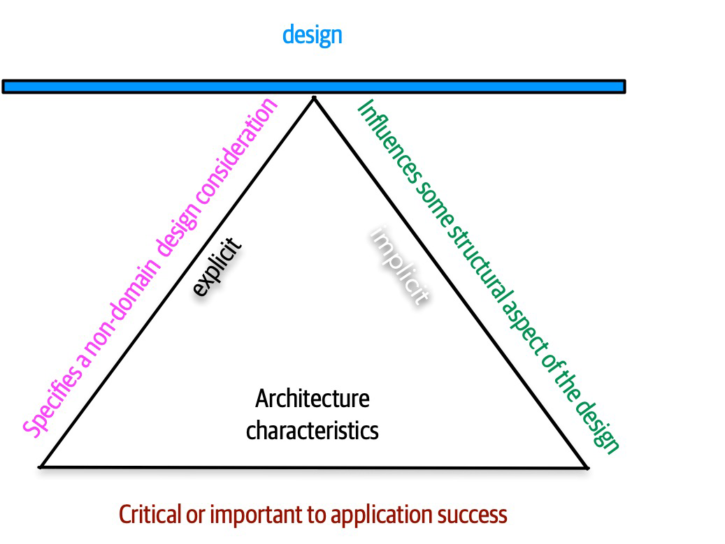
Figure 4-2. The differentiating features of architecture characteristics
The definition illustrated in Figure 4-2 consists of the three components listed, in addition to a few modifiers:
- Specifies a nondomain design consideration
-
When designing an application, the requirements specify what the application should do; architecture characteristics specify operational and design criteria for success, concerning how to implement the requirements and why certain choices were made. For example, a common important architecture characteristic specifies a certain level of performance for the application, which often doesn’t appear in a requirements document. Even more pertinent: no requirements document states “prevent technical debt,” but it is a common design consideration for architects and developers. We cover this distinction between explicit and implicit characteristics in depth in “Extracting Architecture Characteristics from Domain Concerns”.
- Influences some structural aspect of the design
The primary reason architects try to describe architecture characteristics on projects concerns design considerations: does this architecture characteristic require special structural consideration to succeed? For example, security is a concern in virtually every project, and all systems must take a baseline of precautions during design and coding. However, it rises to the level of architecture characteristic when the architect needs to design something special. Consider two cases surrounding payment in a example system:
- Third-party payment processor
If an integration point handles payment details, then the architecture shouldn’t require special structural considerations. The design should incorporate standard security hygiene, such as encryption and hashing, but doesn’t require special structure.
- In-application payment processing
If the application under design must handle payment processing, the architect may design a specific module, component, or service for that purpose to isolate the critical security concerns structurally. Now, the architecture characteristic has an impact on both architecture and design.
Of course, even these two criteria aren’t sufficient in many cases to make this determination: past security incidents, the nature of the integration with the third party, and a host of other criteria may be present during this decision. Still, it shows some of the considerations architects must make when determining how to design for certain capabilities.
- Critical or important to application success
-
Applications could support a huge number of architecture characteristics…but shouldn’t. Support for each architecture characteristic adds complexity to the design. Thus, a critical job for architects lies in choosing the fewest architecture characteristics rather than the most possible.
We further subdivide architecture characteristics into implicit versus explicit architecture characteristics.
Architectural Characteristics (Partially) Listed
Despite the volume and scale, architects commonly separate architecture characteristics into broad categories. The following sections describe a few, along with some examples.
Operational Architecture Characteristics
| Term | Definition |
|---|---|
Availability | How long the system will need to be available (if 24/7, steps need to be in place to allow the system to be up and running quickly in case of any failure). |
Continuity | Disaster recovery capability. |
Performance | Includes stress testing, peak analysis, analysis of the frequency of functions used, capacity required, and response times. Performance acceptance sometimes requires an exercise of its own, taking months to complete. |
Recoverability | Business continuity requirements (e.g., in case of a disaster, how quickly is the system required to be on-line again?). This will affect the backup strategy and requirements for duplicated hardware. |
Reliability/safety | Assess if the system needs to be fail-safe, or if it is mission critical in a way that affects lives. If it fails, will it cost the company large sums of money? |
Robustness | Ability to handle error and boundary conditions while running if the internet connection goes down or if there’s a power outage or hardware failure. |
Scalability | Ability for the system to perform and operate as the number of users or requests increases. |
Operational architecture characteristics heavily overlap with operations and DevOps concerns, forming the intersection of those concerns in many software projects.
Structural Architecture Characteristics
Architects must concern themselves with code structure as well.
| Term | Definition |
|---|---|
Configurability | Ability for the end users to easily change aspects of the software’s configuration (through usable interfaces). |
Extensibility | How important it is to plug new pieces of functionality in. |
Installability | Ease of system installation on all necessary platforms. |
Leverageability/reuse | Ability to leverage common components across multiple products. |
Localization | Support for multiple languages on entry/query screens in data fields; on reports, multibyte character requirements and units of measure or currencies. |
Maintainability | How easy it is to apply changes and enhance the system? |
Portability | Does the system need to run on more than one platform? (For example, does the frontend need to run against Oracle as well as SAP DB? |
Supportability | What level of technical support is needed by the application? What level of logging and other facilities are required to debug errors in the system? |
Upgradeability | Ability to easily/quickly upgrade from a previous version of this application/solution to a newer version on servers and clients. |
Cross-Cutting Architecture Characteristics
While many architecture characteristics fall into easily recognizable categories,
| Term | Definition |
|---|---|
Accessibility | Access to all your users, including those with disabilities like colorblindness or hearing loss. |
Archivability | Will the data need to be archived or deleted after a period of time? (For example, customer accounts are to be deleted after three months or marked as obsolete and archived to a secondary database for future access.) |
Authentication | Security requirements to ensure users are who they say they are. |
Authorization | Security requirements to ensure users can access only certain functions within the application (by use case, subsystem, webpage, business rule, field level, etc.). |
Legal | What legislative constraints is the system operating in (data protection, Sarbanes Oxley, GDPR, etc.)? What reservation rights does the company require? Any regulations regarding the way the application is to be built or deployed? |
Privacy | Ability to hide transactions from internal company employees (encrypted transactions so even DBAs and network architects cannot see them). |
Security | Does the data need to be encrypted in the database? Encrypted for network communication between internal systems? What type of authentication needs to be in place for remote user access? |
Supportability | What level of technical support is needed by the application? What level of logging and other facilities are required to debug errors in the system? |
Usability/achievability | Level of training required for users to achieve their goals with the application/solution. Usability requirements need to be treated as seriously as any other architectural issue. |
Any list of architecture characteristics will necessarily be an incomplete list; any software may invent important architectural characteristics based on unique factors (see “Italy-ility” for an example).
- Performance efficiency
- Measure of the performance relative to the amount of resources used under known conditions.This includes time behavior (measure of response, processing times, and/or throughput rates), resource utilization (amounts and types of resources used), and capacity (degree to which the maximum established limits are exceeded).
- Compatibility
- Degree to which a product, system, or component can exchange information with other products, systems, or components and/or perform its required functions while sharing the same hardware or software environment.It includes coexistence (can perform its required functions efficiently while sharing a common environment and resources with other products) and interoperability (degree to which two or more systems can exchange and utilize information).
- Usability
- Users can use the system effectively, efficiently, and satisfactorily for its intended purpose.It includes appropriateness recognizability (users can recognize whether the software is appropriate for their needs), learnability (how easy users can learn how to use the software), user error protection (protection against users making errors), and accessibility (make the software available to people with the widest range of characteristics and capabilities).
- Reliability
- Degree to which a system functions under specified conditions for a specified period of time.This characteristic includes subcategories such as maturity (does the software meet the reliability needs under normal operation), availability (software is operational and accessible), fault tolerance (does the software operate as intended despite hardware or software faults), and recoverability (can the software recover from failure by recovering any affected data and reestablish the desired state of the system.
- Security
- Degree the software protects information and data so that people or other products or systems have the degree of data access appropriate to their types and levels of authorization.This family of characteristics includes confidentiality (data is accessible only to those authorized to have access), integrity (the software prevents unauthorized access to or modification of software or data), nonrepudiation, (can actions or events be proven to have taken place), accountability (can user actions of a user be traced), and authenticity (proving the identity of a user).
- Maintainability
- Represents the degree of effectiveness and efficiency to which developers can modify the software to improve it, correct it, or adapt it to changes in environment and/or requirements.This characteristic includes modularity (degree to which the software is composed of discrete components), reusability (degree to which developers can use an asset in more than one system or in building other assets), analyzability (how easily developers can gather concrete metrics about the software), modifiability (degree to which developers can modify the software without introducing defects or degrading existing product quality), and testability (how easily developers and others can test the software).
- Portability
- Degree to which developers can transfer a system, product, or component from one hardware, software, orother operational or usage environment to another.This characteristic includes the subcharacteristics of adaptability (can developers effectively and efficiently adapt the software for different or evolving hardware, software, or other operational or usage environments), installability (can the software be installed and/or uninstalled in a specified environment), and replaceability (how easily developers can replace the functionality with other software).
- Functional suitability
- This characteristic represents the degree to which a product or system provides functions that meet stated and implied needs when used under specified conditions. This characteristic is composed of the following subcharacteristics:
- Functional completeness
- Degree to which the set of functions covers all the specified tasks and user objectives.
- Functional correctness
- Degree to which a product or system provides the correct results with the needed degree of precision.
- Functional appropriateness
- Degree to which the functions facilitate the accomplishment of specified tasks and objectives. These are not architecture characteristics but rather the motivational requirements to build the software. This illustrates how thinking about the relationship between architecture characteristics and the problem domain has evolved. We cover this evolution inChapter 7.
Trade-Offs and Least Worst Architecture
A metaphor will help illustrate this interconnectivity. Apparently, pilots often struggle learning to fly helicopters because it requires a control for each hand and each foot, and changing one impacts the others. Thus, flying a helicopter is a balancing exercise, which nicely describes the trade-off process when choosing architecture characteristics. Each architecture characteristic that an architect designs support for potentially complicates the overall design.
Tip
Never shoot for the best architecture, but rather the least worst architecture.
Too many architecture characteristics leads to generic solutions that are trying to solve every business problem, and those architectures rarely work because the design becomes unwieldy.
Chapter 5. Identifying Architectural Characteristics
Identifying the driving architectural characteristics is one of the first steps in creating an architecture or determining the validity of an existing architecture.
An architect uncovers architecture characteristics in at least three ways by extracting from domain concerns, requirements, and implicit domain knowledge. We previously discussed implicit characteristics and we cover the other two here.
Extracting Architecture Characteristics from Domain Concerns
Many architects and domain stakeholders want to prioritize the final list of architecture characteristics that the application or system must support. While this is certainly desirable, in most cases it is a fool’s errand and will not only waste time, but also produce a lot of unnecessary frustration and disagreement with the key stakeholders. Rarely will all stakeholders agree on the priority of each and every characteristic. A better approach is to have the domain stakeholders select the top three most important characteristics from the final list (in any order). Not only is this much easier to gain consensus on, but it also fosters discussions about what is most important and helps the architect analyze trade-offs when making vital architecture decisions.
| Domain concern | Architecture characteristics |
|---|---|
Mergers and acquisitions | Interoperability, scalability, adaptability, extensibility |
Time to market | Agility, testability, deployability |
User satisfaction | Performance, availability, fault tolerance, testability, deployability, agility, security |
Competitive advantage | Agility, testability, deployability, scalability, availability, fault tolerance |
Time and budget | Simplicity, feasibility |
One important thing to note is that agility does not equal time to market. Rather, it is agility + testability + deployability.
Extracting Architecture Characteristics from Requirements
Case Study: Silicon Sandwiches
- Description
-
A national sandwich shop wants to enable online ordering (in addition to its current call-in service).
- Users
-
Thousands, perhaps one day millions
- Requirements
-
-
Users will place their order, then be given a time to pick up their sandwich and directions to the shop (which must integrate with several external mapping services that include traffic information)
-
If the shop offers a delivery service, dispatch the driver with the sandwich to the user
-
Mobile-device accessibility
-
Offer national daily promotions/specials
-
Offer local daily promotions/specials
-
Accept payment online, in person, or upon delivery
-
- Additional context
-
-
Sandwich shops are franchised, each with a different owner
-
Parent company has near-future plans to expand overseas
-
Corporate goal is to hire inexpensive labor to maximize profit
-
Given this scenario, how would an architect derive architecture characteristics? Each part of the requirement might contribute to one or more aspects of architecture (and many will not). The architect doesn’t design the entire system here—considerable effort must still go into crafting code to solve the domain statement. Instead, the architect looks for things that influence or impact the design, particularly structural.
First, separate the candidate architecture characteristics into explicit and implicit characteristics.
Explicit Characteristics
Explicit architecture characteristics appear in a requirements specification as part of the necessary design. For example, a shopping website may aspire to support a particular number of concurrent users, which domain analysts specify in the requirements. An architect should consider each part of the requirements to see if it contributes to an architecture characteristic. But first, an architect should consider domain-level predictions about expected metrics, as represented in the Users section of the kata.
One of the first details that should catch an architect’s eye is the number of users: currently thousands, perhaps one day millions (this is a very ambitious sandwich shop!). Thus, scalability—the ability to handle a large number of concurrent users without serious performance degradation—is one of the top architecture characteristics. Notice that the problem statement didn’t explicitly ask for scalability, but rather expressed that requirement as an expected number of users. Architects must often decode domain language into engineering equivalents.
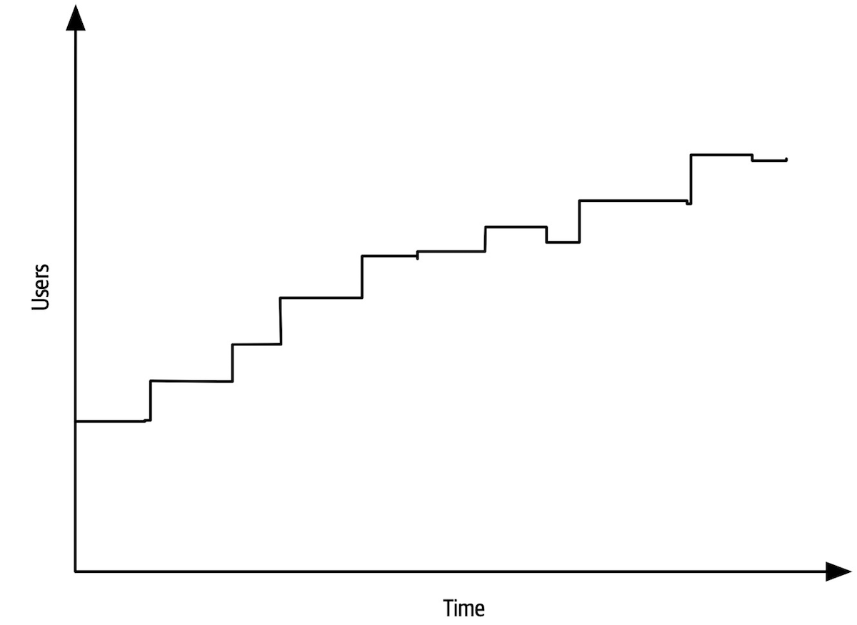
Figure 5-1. Scalability measures the performance of concurrent users
Elasticity, on the other hand, measures bursts of traffic, as shown in Figure 5-2.
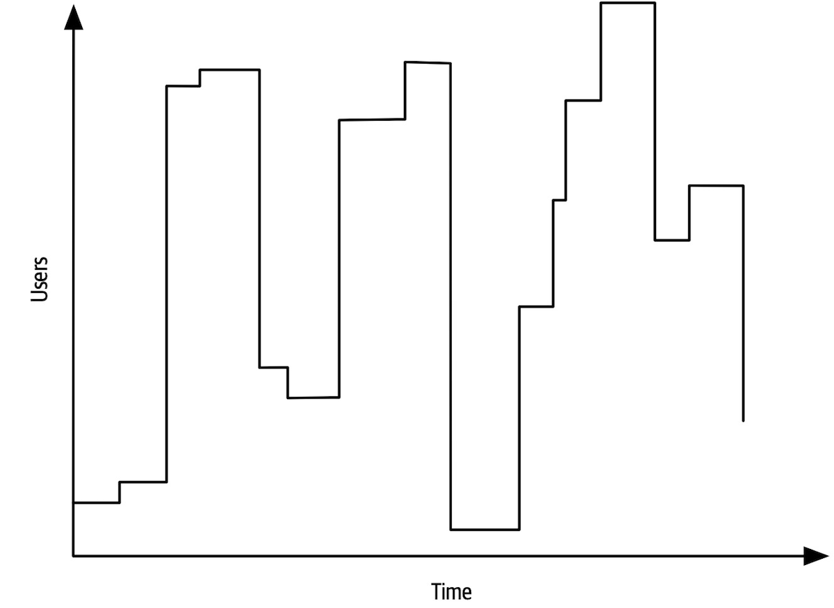
Figure 5-2. Elastic systems must withstand bursts of users
Some systems are scalable but not elastic. For example, consider a hotel reservation system. Absent special sales or events, the number of users is probably consistent. In contrast, consider a concert ticket booking system. As new tickets go on sale, fervent fans will flood the site, requiring high degrees of elasticity. Often, elastic systems also need scalability: the ability to handle bursts and high numbers of concurrent users.
The requirement for elasticity did not appear in the Silicon Sandwiches requirements, yet the architect should identify this as an important consideration. Requirements sometimes state architecture characteristics outright, but some lurk inside the problem domain. Consider a sandwich shop. Is its traffic consistent throughout the day? Or does it endure bursts of traffic around mealtimes? Almost certainly the latter. Thus, a good architect should identify this potential architecture characteristic.
An architect should consider each of these business requirements in turn to see if architecture characteristics exist:
-
Users will place their order, then be given a time to pick up their sandwich and directions to the shop (which must provide the option to integrate with external mapping services that include traffic information).
External mapping services imply integration points, which may impact aspects such as reliability. For example, if a developer builds a system that relies on a third-party system, yet calling it fails, it impacts the reliability of the calling system. However, architects must also be wary of over-specifying architecture characteristics. What if the external traffic service is down? Should the Silicon Sandwiches site fail, or should it just offer slightly less efficiency without traffic information? Architects should always guard against building unnecessary brittleness or fragility into designs.
-
If the shop offers a delivery service, dispatch the driver with the sandwich to the user.
No special architecture characteristics seem necessary to support this requirement.
-
Mobile-device accessibility.
This requirement will primarily affect the design of the application, pointing toward building either a portable web application or several native web applications. Given the budget constraints and simplicity of the application, an architect would likely deem it overkill to build multiple applications, so the design points toward a mobile-optimized web application. Thus, the architect may want to define some specific performance architecture characteristics for page load time and other mobile-sensitive characteristics. Notice that the architect shouldn’t act alone in situations like this, but should instead collaborate with user experience designers, domain stakeholders, and other interested parties to vet decisions like this.
-
Offer national daily promotions/specials.
-
Offer local daily promotions/specials.
Both of these requirements specify customizability across both promotions and specials. Notice that requirement 1 also implies customized traffic information based on address.
Based on all three of these requirements, the architect may consider customizability as an architecture characteristic. For example, an architecture style such as microkernel architecture supports customized behavior extremely well by defining a plug-in architecture. In this case, the default behavior appears in the core, and developers write the optional customized parts, based on location, via plug-ins. However, a traditional design can also accommodate this requirement via design patterns (such as Template Method). This conundrum is common in architecture and requires architects to constantly weight trade-offs between competing options. We discuss particular trade-off in more detail in“Design Versus Architecture and Trade-Offs”. -
Accept payment online, in person, or upon delivery.
Online payments imply security, but nothing in this requirement suggests a particularly heightened level of security beyond what’s implicit.
-
Sandwich shops are franchised, each with a different owner.
This requirement may impose cost restrictions on the architecture—the architect should check the feasibility (applying constraints like cost, time, and staff skill set) to see if a simple or sacrificial architecture is warranted.
Parent company has near-future plans to expand overseas.
This requirement implies internationalization, or i18n.Many design techniques exist to handle this requirement, which shouldn’t require special structure to accommodate. This will, however, certainly drive design decisions.Corporate goal is to hire inexpensive labor to maximize profit.
This requirement suggests that usability will be important, but again is more concerned with design than architecture characteristics.
We also want to define performance numbers in conjunction with scalability numbers. In other words, we must establish a baseline of performance without particular scale, as well as determine what an acceptable level of performance is given a certain number of users. Quite often, architecture characteristics interact with one another, forcing architects to define them in relation to one another.
Implicit Characteristics
Many architecture characteristics aren’t specified in requirements documents, yet they make up an important aspect of the design.
There are no wrong answers in architecture, only expensive ones.
Chapter 6. Measuring and Governing Architecture Characteristics
Architects must deal with the extraordinarily wide variety of architecture characteristics across all different aspects of software projects.
Measuring Architecture Characteristics
Several common problems exist around the definition of architecture characteristics in organizations:
- They aren’t physics
-
Many architecture characteristics in common usage have vague meanings. For example, how does an architect design for agility or deployability? The industry has wildly differing perspectives on common terms, sometimes driven by legitimate differing contexts, and sometimes accidental.
- Wildly varying definitions
-
Even within the same organization, different departments may disagree on the definition of critical features such as performance. Until developers, architecture, and operations can unify on a common definition, a proper conversation is difficult.
- Too composite
-
Many desirable architecture characteristics comprise many others at a smaller scale. For example, developers can decompose agility into characteristics such as modularity, deployability, and testability.
Objective definitions for architecture characteristics solve all three problems: by agreeing organization-wide on concrete definitions for architecture characteristics, teams create a ubiquitous language around architecture. Also, by encouraging objective definitions, teams can unpack composite characteristics to uncover measurable features they can objectively define.
Operational Measures
High-level teams don’t just establish hard performance numbers; they base their definitions on statistical analysis. For example, say a video streaming service wants to monitor scalability. Rather than set an arbitrary number as the goal, engineers measure the scale over time and build statistical models, then raise alarms if the real-time metrics fall outside the prediction models. A failure can mean two things: the model is incorrect (which teams like to know) or something is amiss (which teams also like to know).
The kinds of characteristics that teams can now measure are evolving rapidly, in conjunction with tools and nuanced understanding. For example, many teams recently focused on performance budgets for metrics such as first contentful paint and first CPU idle, both of which speak volumes about performance issues for users of webpages on mobile devices. As devices, targets, capabilities, and myriad other things change, teams will find new things and ways to measure.
Structural Measures
An obvious measurable aspect of code is complexity, defined by the cyclomatic complexity metric.
Architects and developers universally agree that overly complex code represents a code smell; it harms virtually every one of the desirable characteristics of code bases: modularity, testability, deployability, and so on. Yet if teams don’t keep an eye on gradually growing complexity, that complexity will dominate the code base.
Process Measures
Governance and Fitness Functions
Governing Architecture Characteristics
Fitness Functions
Practices in evolutionary architecture borrow this
- Architecture fitness function
-
Any mechanism that provides an objective integrity assessment of some architecture characteristic or combination of architecture characteristics
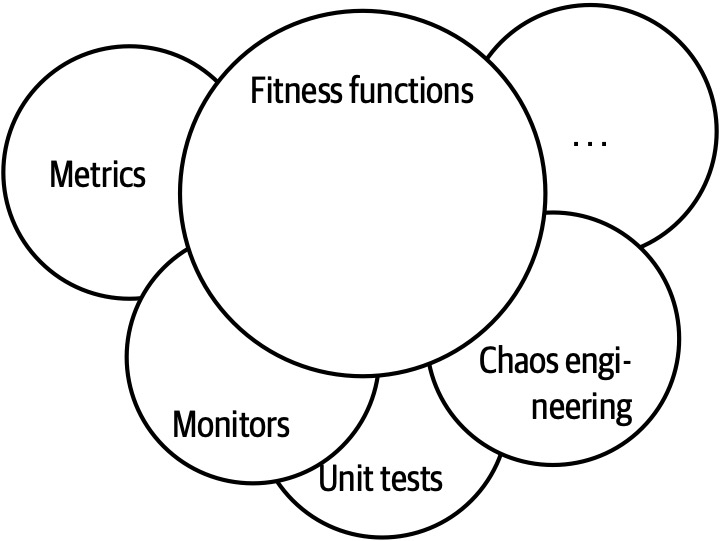
Figure 6-2. The mechanisms of fitness functions
Many different tools may be used to implement fitness functions, depending on the architecture characteristics. For example, in “Coupling” we introduced metrics to allow architects to assess modularity.
Cyclic dependencies
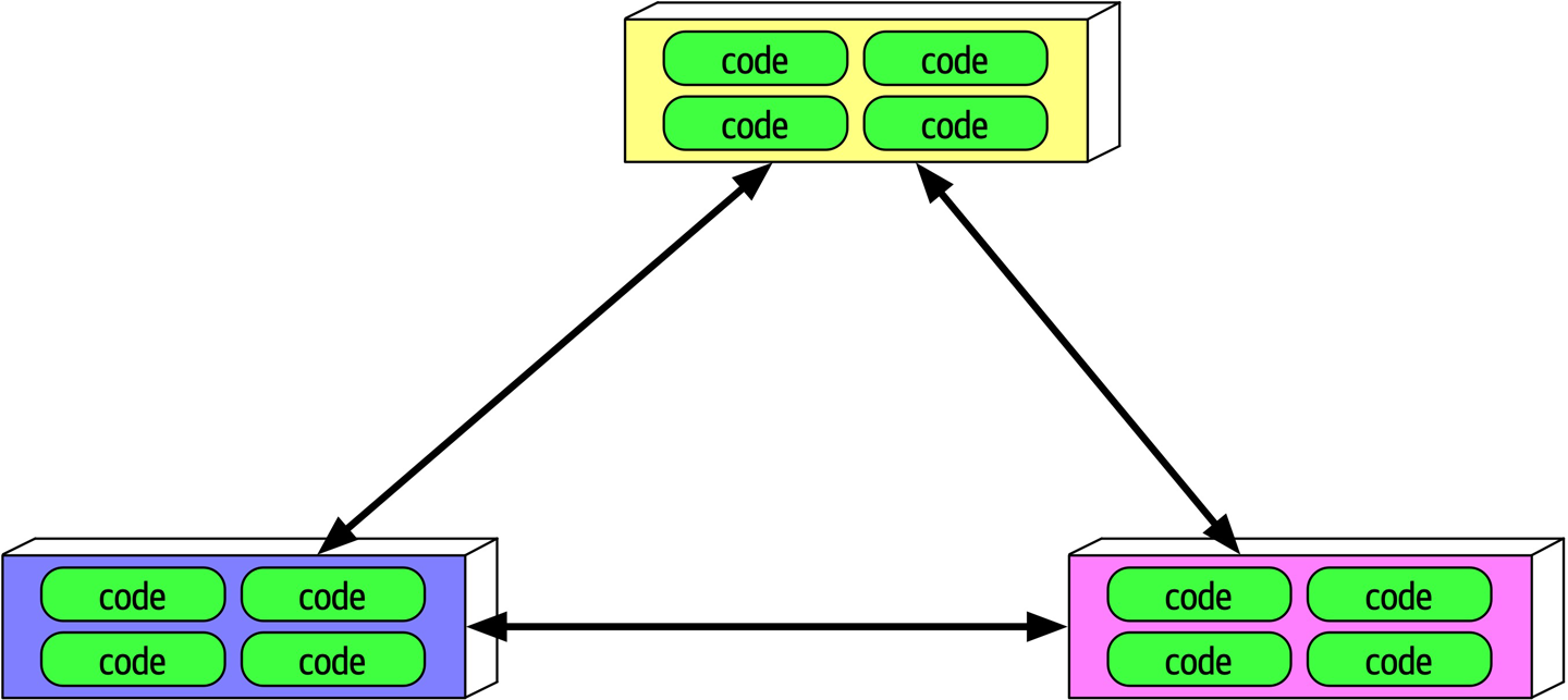
Figure 6-3. Cyclic dependencies between components
In Figure 6-3, each component references something in the others. Having a network of components such as this damages modularity because a developer cannot reuse a single component without also bringing the others along. And, of course, if the other components are coupled to other components, the architecture tends more and more toward the Big Ball of Mud anti-pattern. How can architects govern this behavior without constantly looking over the shoulders of trigger-happy developers?
Example 6-2. Fitness function to detect component cycles
publicclassCycleTest{privateJDependjdepend;@BeforeEachvoidinit(){jdepend=newJDepend();jdepend.addDirectory("/path/to/project/persistence/classes");jdepend.addDirectory("/path/to/project/web/classes");jdepend.addDirectory("/path/to/project/thirdpartyjars");}@TestvoidtestAllPackages(){Collectionpackages=jdepend.analyze();assertEquals("Cycles exist",false,jdepend.containsCycles());}}
In the code, an architect uses the metrics tool JDepend to check the dependencies between packages.
Distance from the main sequence fitness function
Example 6-3. Distance from the main sequence fitness function
@TestvoidAllPackages(){doubleideal=0.0;doubletolerance=0.5;// project-dependentCollectionpackages=jdepend.analyze();Iteratoriter=packages.iterator();while(iter.hasNext()){JavaPackagep=(JavaPackage)iter.next();assertEquals("Distance exceeded: "+p.getName(),ideal,p.distance(),tolerance);}}
In the code, the architect uses JDepend to establish a threshold for acceptable values, failing the test if a class falls outside the range.
This is both an example of an objective measure for an architecture characteristic and the importance of collaboration between developers and architects when designing and implementing fitness functions. The intent is not for a group of architects to ascend to an ivory tower and develop esoteric fitness functions that developers cannot understand.
Tip
Architects must ensure that developers understand the purpose of the fitness function before imposing it on them.
The sophistication of fitness function tools has increased over the last few years, including some special purpose tools.
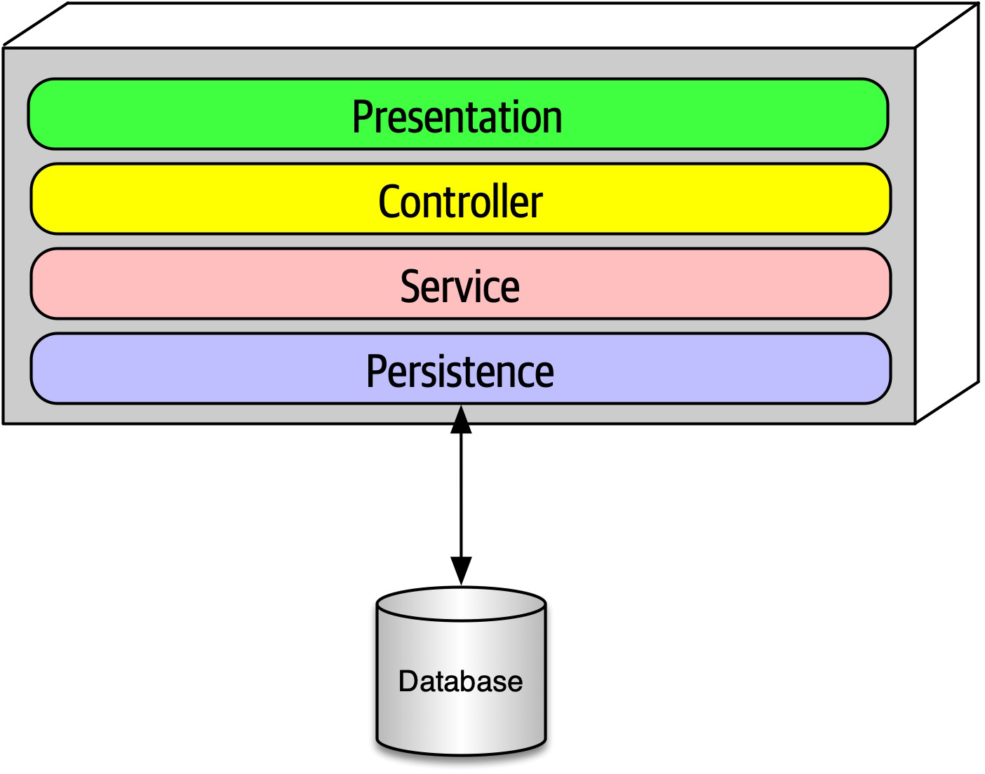
Figure 6-4. Layered architecture
When designing a layered monolith such as the one in Figure 6-4, the architect defines the layers for good reason (motivations, trade-offs, and other aspects of the layered architecture are described in Chapter 10). However, how can the architect ensure that developers will respect those layers? Some developers may not understand the importance of the patterns, while others may adopt a “better to ask forgiveness than permission” attitude because of some overriding local concern such as performance. But allowing implementers to erode the reasons for the architecture hurts the long-term health of the architecture.
Example 6-4. ArchUnit fitness function to govern layers
layeredArchitecture().layer("Controller").definedBy("..controller..").layer("Service").definedBy("..service..").layer("Persistence").definedBy("..persistence..").whereLayer("Controller").mayNotBeAccessedByAnyLayer().whereLayer("Service").mayOnlyBeAccessedByLayers("Controller").whereLayer("Persistence").mayOnlyBeAccessedByLayers("Service")
In Example 6-4, the architect defines the desirable relationship between layers and writes a verification fitness function to govern it.
Example 6-5. NetArchTest for layer dependencies
// Classes in the presentation should not directly reference repositoriesvarresult=Types.InCurrentDomain().That().ResideInNamespace("NetArchTest.SampleLibrary.Presentation").ShouldNot().HaveDependencyOn("NetArchTest.SampleLibrary.Data").GetResult().IsSuccessful;
Another example
Chapter 7. Scope of Architecture Characteristics
A prevailing axiomatic assumption in the software architecture world had traditionally placed the scope of architecture characteristics at the system level.
When evaluating many operational architecture characteristics, an architect must consider dependent components outside the code base that will impact those characteristics. Thus, architects need another method to measure these kinds of dependencies. That lead the Building Evolutionary Architectures authors to define the term architecture quantum.
Coupling and Connascence
- Connascence
-
Two components are connascent if a change in one would require the other to be modified in order to maintain the overall correctness of the system
Architectural Quanta and Granularity
- Architecture quantum
-
An independently deployable artifact with high functional cohesion and synchronous connascence
This definition contains several parts, dissected here:
- Independently deployable
- An architecture quantum includes all the necessary components to function independently from other parts of the architecture. For example, if an application uses a database, it is part of the quantum because the system won’t function without it. This requirement means that virtually all legacy systems deployed using a single database by definition form a quantum of one.However, in the microservices architecture style, each service includes its own database (part of the bounded context driving philosophy in microservices, described in detail inChapter 17), creating multiple quanta within that architecture.
- High functional cohesion
-
Cohesion in component design refers to how well the contained code is unified in purpose.
For example, aCustomercomponent with properties and methods all pertaining to a Customer entity exhibits high cohesion; whereas aUtilitycomponent with a random collection of miscellaneous methods would not.High functional cohesion implies that an architecture quantum does something purposeful. This distinction matters little in traditional monolithic applications with a single database. However, in microservices architectures, developers typically design each service to match a single workflow (a bounded context, as described in“Domain-Driven Design’s Bounded Context”), thus exhibiting high functional cohesion. - Synchronous connascence
-
Synchronous connascence implies synchronous calls within an application context or between distributed services that form this architecture quantum.
For example, if one service in a microservices architecture calls another one synchronously, each service cannot exhibit extreme differences in operational architecture characteristics. If the caller is much more scalable than the callee, timeouts and other reliability concerns will occur. Thus, synchronous calls create dynamic connascence for the length of the call—if one is waiting for the other, their operational architecture characteristics must be the same for the duration of the call.
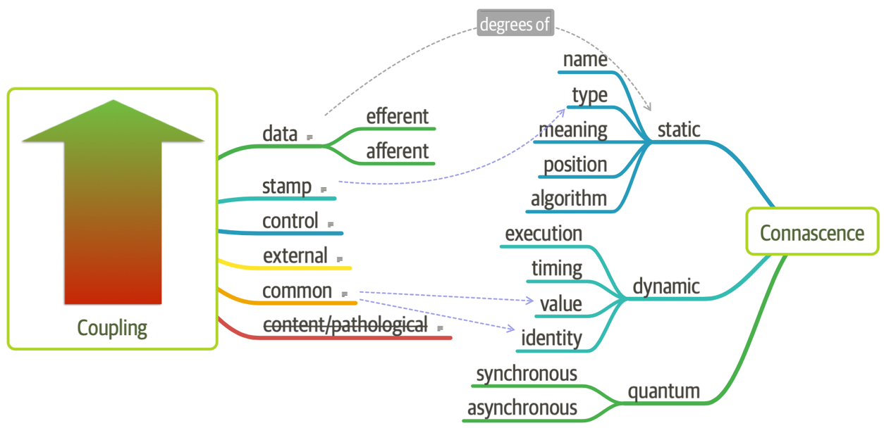
Figure 7-1. Adding quantum connascence to the unified diagram
For another example, consider a microservices architecture with a Payment service and an Auction service. When an auction ends, the Auction service sends payment information to the Payment service. However, let’s say that the payment service can only handle a payment every 500 ms—what happens when a large number of auctions end at once? A poorly designed architecture would allow the first call to go through and allow the others to time out. Alternatively, an architect might design an asynchronous communication link between Payment and Auction, allowing the message queue to temporarily buffer differences.
Case Study: Going, Going, Gone
- Description
-
An auction company wants to take its auctions online to a nationwide scale. Customers choose the auction to participate in, wait until the auction begins, then bid as if they are there in the room with the auctioneer.
- Users
-
Scale up to hundreds of participants per auction, potentially up to thousands of participants, and as many simultaneous auctions as possible.
- Requirements
-
-
Auctions must be as real-time as possible.
-
Bidders register with a credit card; the system automatically charges the card if the bidder wins.
-
Participants must be tracked via a reputation index.
-
Bidders can see a live video stream of the auction and all bids as they occur.
-
Both online and live bids must be received in the order in which they are placed.
-
- Additional context
-
-
Auction company is expanding aggressively by merging with smaller competitors.
-
Budget is not constrained. This is a strategic direction.
-
Company just exited a lawsuit where it settled a suit alleging fraud.
-
-
“Nationwide scale,” “scale up to hundreds of participants per auction, potentially up to thousands of participants, and as many simultaneous auctions as possible,” “auctions must be as real-time as possible.”
Each of these requirements implies both scalability to support the sheer number of
users and elasticity to support the bursty nature of auctions. While the requirements explicitly call out scalability, elasticity represents an implicit characteristics based on the problem domain. When considering auctions, do users all politely spread themselves out during the course of bidding, or do they become more frantic near the end? Domain knowledge is crucial for architects to pick up implicit architecture characteristics. Given the real-time nature of auctions, an architect will certainly consider performance a key architecture characteristic. “Bidders register with a credit card; the system automatically charges the card if the bidder wins,” “company just exited a lawsuit where it settled a suit alleging fraud.”
Both these requirements clearly point to security as an architecture characteristic.As covered inChapter 5, security is an implicit architecture characteristic in virtually every application. Thus, architects rely on the second part of the definition of architecture characteristics, that they influence some structural aspect of the design. Should an architect design something special to accommodate security, or will general design and coding hygiene suffice? Architects have developed techniques for handling credit cards safely via design without necessarily building special structure. For example, as long as developers make sure not to store credit card numbers in plain text, to encrypt while in transit, and so on, then the architect shouldn’t have to build special considerations for security.However, the second phrase should make an architect pause and ask for further clarification. Clearly, some aspect of security (fraud) was a problem in the past, thus the architect should ask for further input no matter what level of security they design.
-
“Participants must be tracked via a reputation index.”
This requirement suggests some fanciful names such as “anti-trollability,” but the track part of the requirement might suggest some architecture characteristics such as auditability and loggability.
The deciding factor again goes back to the defining characteristic—is this outside the scope of the problem domain? Architects must remember that the analysis to yield architecture characteristics represents only a small part of the overall effort to design and implement an application—a lot of design work happens past this phase! During this part of architecture definition, architects look for requirements with structural impact not already covered by the domain.Here’s a useful litmus test architects use to make the determination between domain versus architecture characteristics is: does it require domain knowledge to implement, or is it an abstract architecture characteristic? In the Going, Going, Gone kata, an architect upon encountering the phrase “reputation index” would seek out a business analyst or other subject matter expert to explain what they had in mind. In other words, the phrase “reputation index” isn’t a standard definition like more common architecture characteristics.As a counter example, when architects discuss elasticity, the ability to handle bursts of users, they can talk about the architecture characteristic purely in the abstract—it doesn’t matter what kind of application they consider: banking, catalog site, streaming video, and so on. Architects must determine whether a requirement isn’t already encompassed by the domain and requires particular structure, which elevates a consideration to architecture characteristic. “Auction company is expanding aggressively by merging with smaller competitors.”
While this requirement may not have an immediate impact on application design, it might become the determining factor in a trade-off between several options. For example, architects must often choose details such as communication protocols for integration architecture: if integration with newly merged companies isn’t a concern, it frees the architect to choose something highly specific to the problem. On the other hand, an architect may choose something that’s less than perfect to accommodate some additional trade-off, such as interoperability.Subtle implicit architecture characteristics such as this pervade architecture, illustrating why doing the job well presents challenges.-
“Budget is not constrained. This is a strategic direction.”
Some architecture katas impose budget restrictions on the solution to represent a common real-world trade-off. However, in the Going, Going, Gone kata, it does not. This allows the architect to choose more elaborate and/or special-purpose architectures, which will be beneficial given the next requirements.
“Bidders can see a live video stream of the auction and all bids as they occur,” “both online and live bids must be received in the order in which they are placed.”
This requirement presents an interesting architectural challenge, definitely impacting the structure of the application and exposing the futility of treating architecture characteristics as a system-wide evaluation.Consider availability—is that need uniform throughout the architecture? In other words, is the availability of the one bidder more important than availability for one of the hundreds of bidders? Obviously, the architect desires good measures for both, but one is clearly more critical: if the auctioneer cannot access the site, online bids cannot occur for anyone. Reliability commonly appears with availability; it addresses operational aspects such as uptime, as well as data integrity and other measures of how reliable an application is.For example, in an auction site, the architect must ensure that the message ordering is reliably correct, eliminating race conditions and other problems.
This last requirement in the Going, Going, Gone kata highlights the need for a more granular scope in architecture than the system level. Using the architecture quantum measure, architects scope architecture characteristics at the quantum level. For example, in Going, Going, Gone, an architect would notice that different parts of this architecture need different characteristics: streaming bids, online bidders, and the auctioneer are three obvious choices. Architects use the architecture quantum measure as a way to think about deployment, coupling, where data should reside, and communication styles within architectures. In this kata, an architect can analyze the differing architecture characteristics per architecture quantum, leading to hybrid architecture design earlier in the process.
Thus, for Going, Going, Gone, we identified the following quanta and corresponding architecture characteristics:
- Bidder feedback
-
Encompasses the bid stream and video stream of bids
-
Availability
-
Scalability
-
Performance
-
- Auctioneer
-
The live auctioneer
-
Availability
-
Reliability
-
Scalability
-
Elasticity
-
Performance
-
Security
-
- Bidder
Online bidders and bidding
-
Reliability
-
Availability
-
Scalability
- Elasticity
-
Chapter 8. Component-Based Thinking
In Chapter 3, we discussed modules as a collection of related code. However, architects typically think in terms of components, the physical manifestation of a module.
jar files in Java, dll in .NET, gem in Ruby, and so on. In this chapter, we discuss architectural considerations around components, ranging from scope to discovery.Component Scope
Components offer a language-specific mechanism to group artifacts together, often nesting them to create stratification. As shown in Figure 8-1, the simplest component wraps code at a higher level of modularity than classes (or functions, in nonobject-oriented languages).
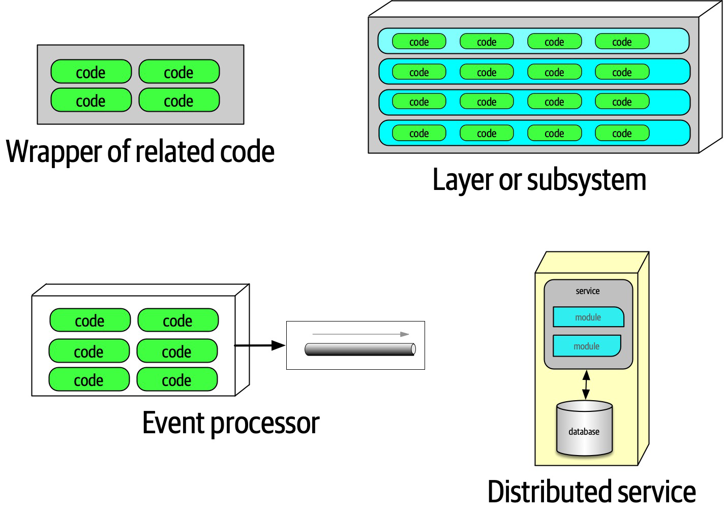
Figure 8-1. Different varieties of components
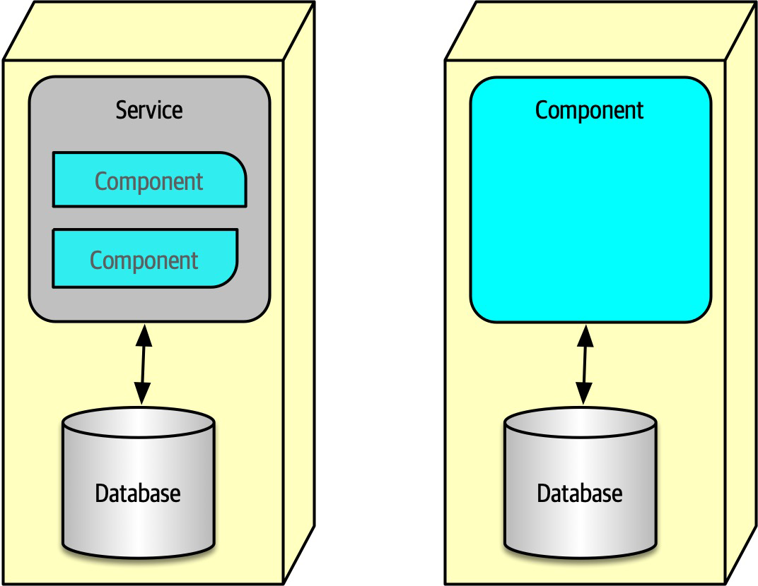
Figure 8-2. A microservice might have so little code that components aren’t necessary
Components form the fundamental modular building block in architecture, making them a critical consideration for architects. In fact, one of the primary decisions an architect must make concerns the top-level partitioning of components in the architecture.
Architect Role
Virtually all the details we cover in this book exist independently from whatever software development process teams use: architecture is independent from the development process.
An architect must identify components as one of the first tasks on a new project. But before an architect can identify components, they must know how to partition the architecture.
Architecture Partitioning
The First Law of Software Architecture states that everything in software is a trade-off, including how architects create components in an architecture.
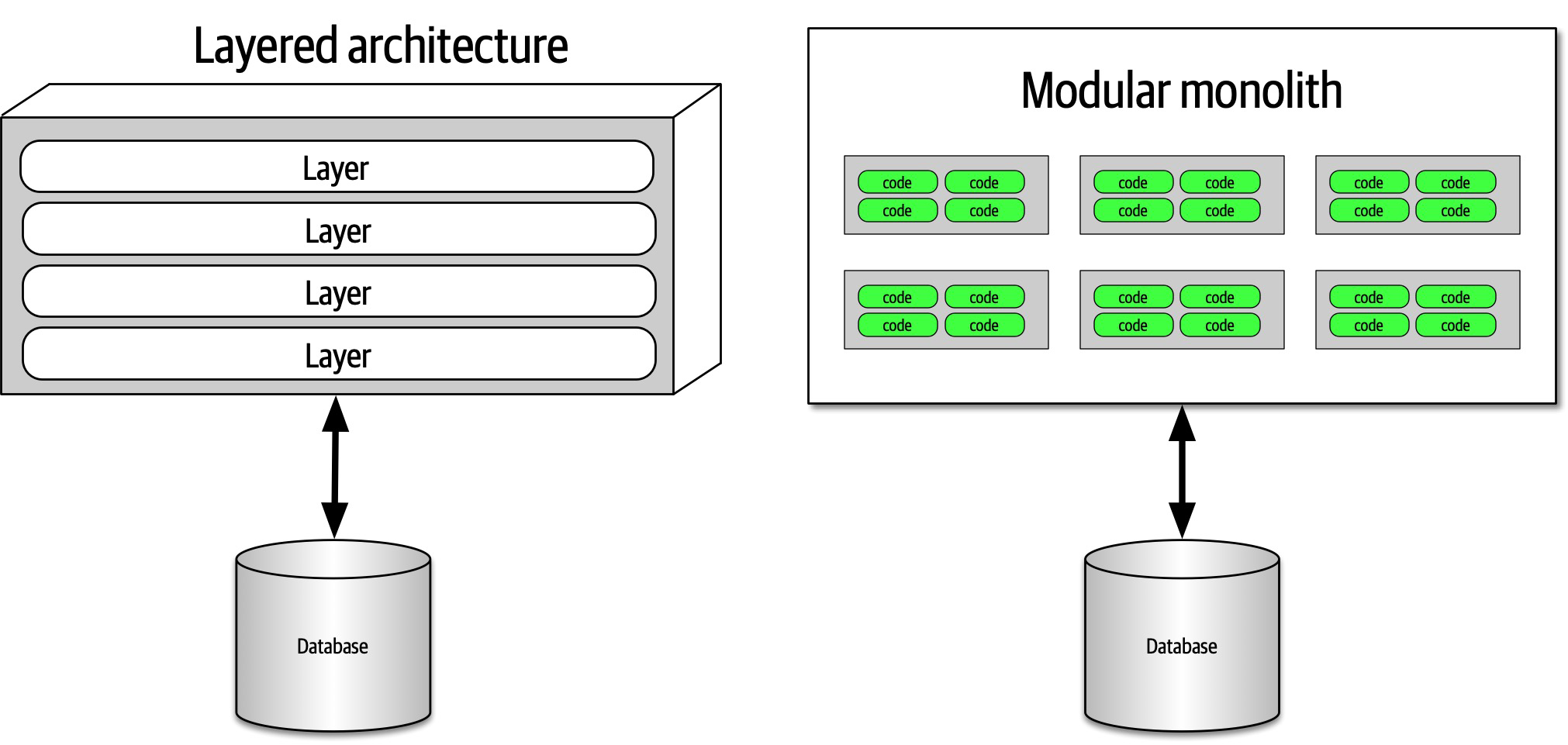
Figure 8-3. Two types of top-level architecture partitioning: layered and modular
In Figure 8-3, one type
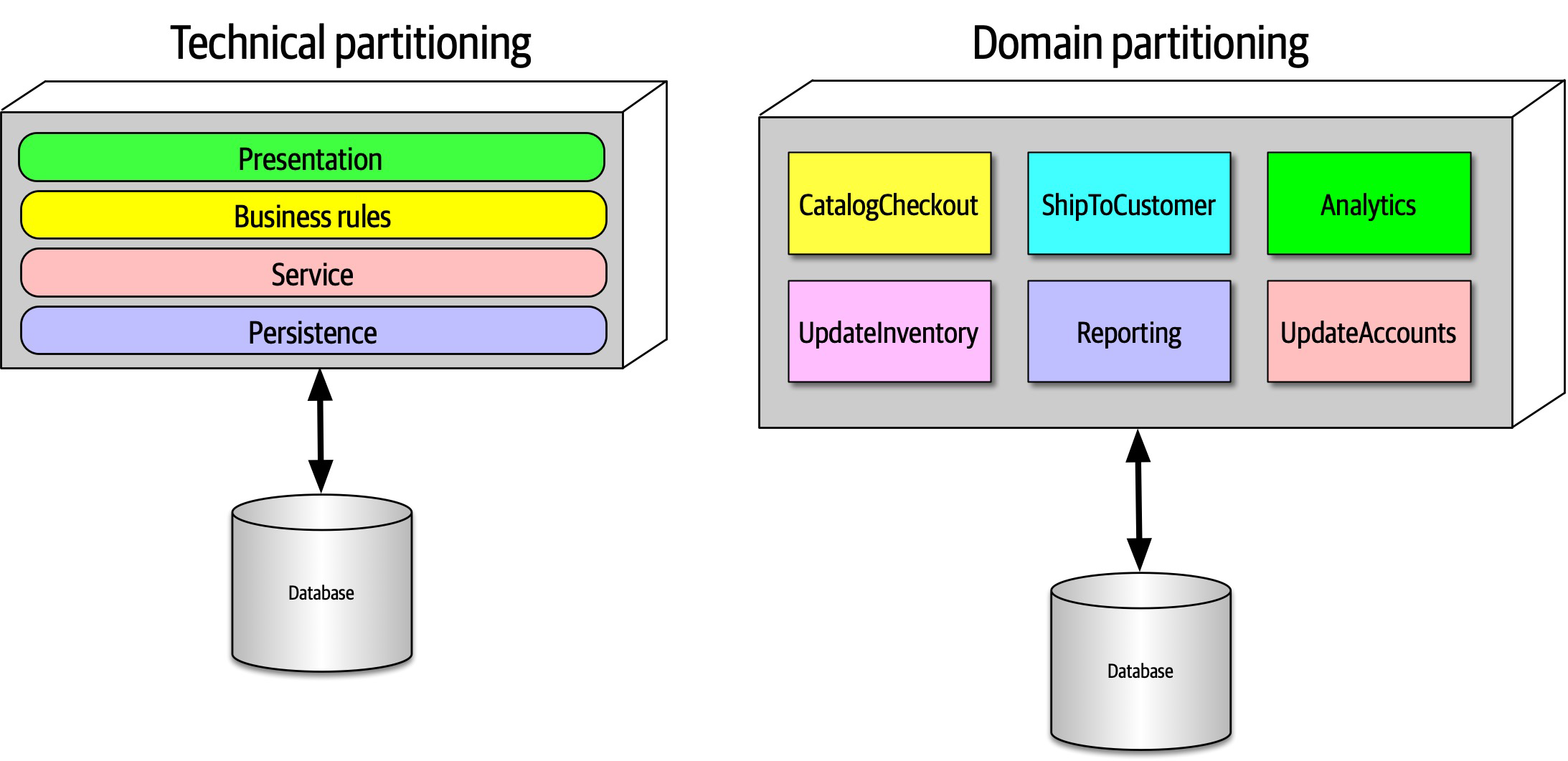
Figure 8-4. Two types of top-level partitioning in architecture
In Figure 8-4, the architect has partitioned the functionality of the system into technical capabilities: presentation, business rules, services, persistence, and so on. This way of organizing a code base certainly makes sense.
An interesting side effect of the predominance of the layered architecture relates to how companies seat different project roles. When using a layered architecture, it makes some sense to have all the backend developers sit together in one department, the DBAs in another, the presentation team in another, and so on. Because of Conway’s law, this makes some sense in those organizations.
One of the fundamental distinctions between different architecture patterns is what type of top-level partitioning each supports, which we cover for each individual pattern. It also has a huge impact on how an architect decides how to initially identify components—does the architect want to partition things technically or by domain?
Architects using technical partitioning organize the components of the system by technical capabilities: presentation, business rules, persistence, and so on. Thus, one of the organizing principles of this architecture is separation of technical concerns.
The separation enforced by technical partitioning enables developers to find certain categories of the code base quickly, as it is organized by capabilities. However, most realistic software systems require workflows that cut across technical capabilities. Consider the common business workflow of CatalogCheckout. The code to handle CatalogCheckout in
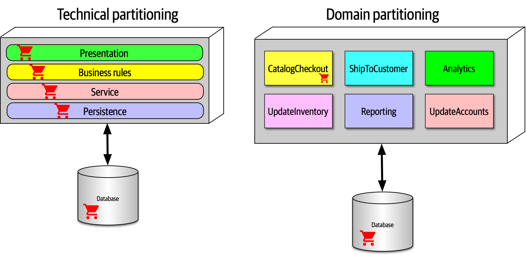
Figure 8-5. Where domains/workflows appear in technical- and domain-partitioned architectures
In Figure 8-5, in the technically partitioned architecture, CatalogCheckout appears in all the layers; the domain is smeared across the technical layers. Contrast this with domain partitioning, which uses a top-level partitioning that organizes components by domain rather than technical capabilities. In Figure 8-5, architects designing the domain-partitioned architecture build top-level components around workflows and/or domains. Each component in the domain partitioning may have subcomponents, including layers, but the top-level partitioning focuses on domains, which better reflects the kinds of changes that most often occur on projects.
Neither of these styles is more correct than the other—refer to the First Law of Software Architecture. That said, we have observed a decided industry trend over the last few years toward domain partitioning for the monolithic and distributed (for example, microservices) architectures. However, it is one of the first decisions an architect must make.
Case Study: Silicon Sandwiches: Partitioning
Consider the case of one of our example katas, “Case Study: Silicon Sandwiches”. When deriving
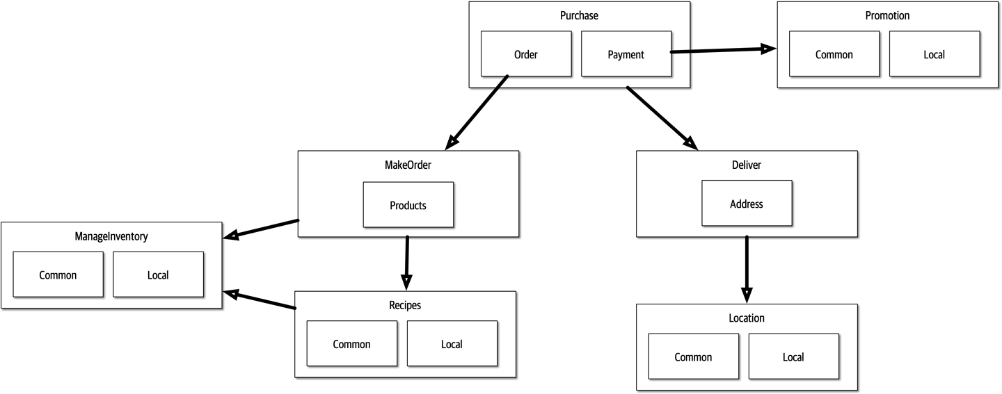
Figure 8-6. A domain-partitioned design for Silicon Sandwiches
In Figure 8-6, the architect has designed around domains (workflows), creating discrete components for Purchase, Promotion, MakeOrder, ManageInventory, Recipes, Delivery, and Location. Within many of these components resides a subcomponent to handle the various types of customization required, covering both common and local variations.
An alternative design isolates the common and local parts into their own partition, illustrated in Figure 8-7. Common and Local represent top-level components, with Purchase and Delivery remaining to handle the workflow.
Which is better? It depends! Each partitioning offers different advantages and drawbacks.
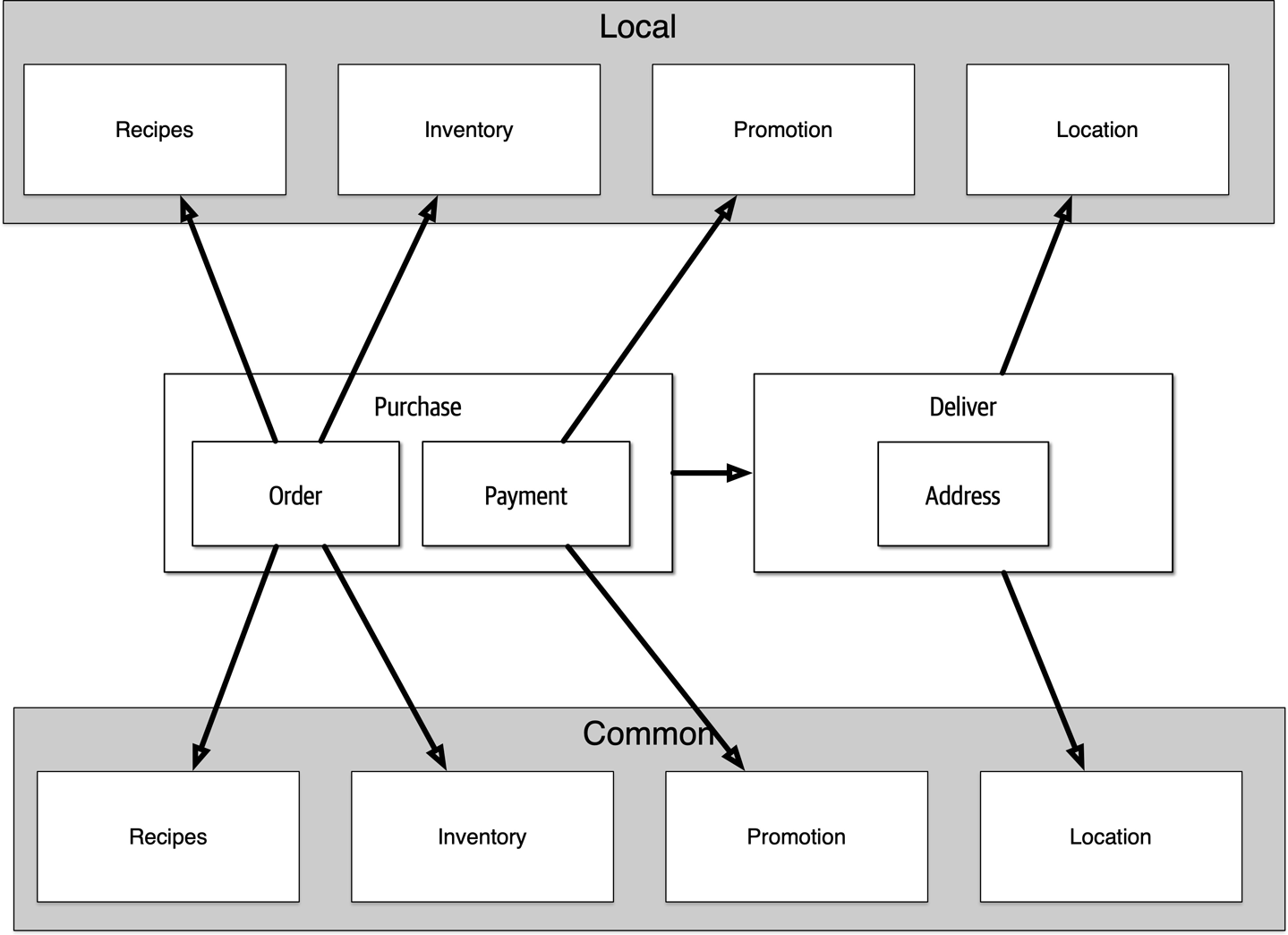
Figure 8-7. A technically partitioned design for Silicon Sandwiches
Domain partitioning
Domain-partitioned architectures separate top-level components by workflows and/or domains.
- Advantages
-
Modeled more closely toward how the business functions rather than an implementation detail
- Easier to utilize the Inverse Conway Maneuver to build cross-functional teams around domains
- Aligns more closely to the modular monolith and microservices architecture styles
-
Message flow matches the problem domain
-
Easy to migrate data and components to distributed architecture
-
- Disadvantage
-
-
Customization code appears in multiple places
-
Technical partitioning
- Advantages
-
-
Clearly separates customization code.
-
Aligns more closely to the layered architecture pattern.
-
- Disadvantages
-
-
Higher degree of global coupling. Changes to either the
CommonorLocalcomponent will likely affect all the other components. -
Developers may have to duplication domain concepts in both
commonandlocallayers. -
Typically higher coupling at the data level. In a system like this, the application and data architects would likely collaborate to create a single database, including customization and domains. That in turn creates difficulties in untangling the data relationships if the architects later want to migrate this architecture to a distributed system.
-
Developer Role
Developers typically take components, jointly designed with the architect role, and further subdivide them into classes, functions, or subcomponents.
Developers should never take components designed by architects as the last word; all software design benefits from iteration. Rather, that initial design should be viewed as a first draft, where implementation will reveal more details and refinements.
Component Identification Flow
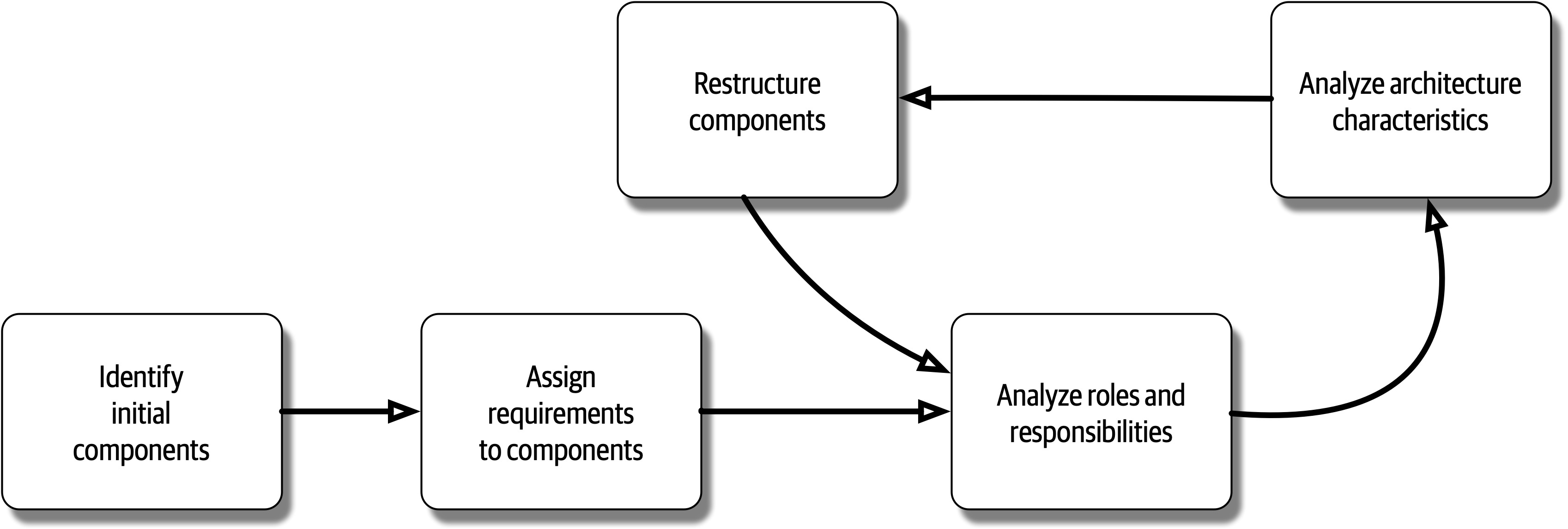
Figure 8-8. Component identification cycle
This cycle describes a generic architecture exposition cycle. Certain specialized domains may insert other steps in this process or change it altogether. For example, in some domains, some code must undergo security or auditing steps in this process. Descriptions of each step in Figure 8-8 appear in the following sections.
Identifying Initial Components
Before any code exists for a software project, the architect must somehow determine what top-level components to begin with, based on what type of top-level partitioning they choose.
Assign Requirements to Components
Analyze Roles and Responsibilities
Analyze Architecture Characteristics
Restructure Components
Component Granularity
Component Design
Discovering Components
Architects, often in collaboration with other roles such as developers, business analysts, and subject matter experts, create an initial component design based on general knowledge of the system and how they choose to decompose it, based on technical or domain partitioning. The team goal is an initial design that partitions the problem space into coarse chunks that take into account differing architecture characteristics.
Entity trap
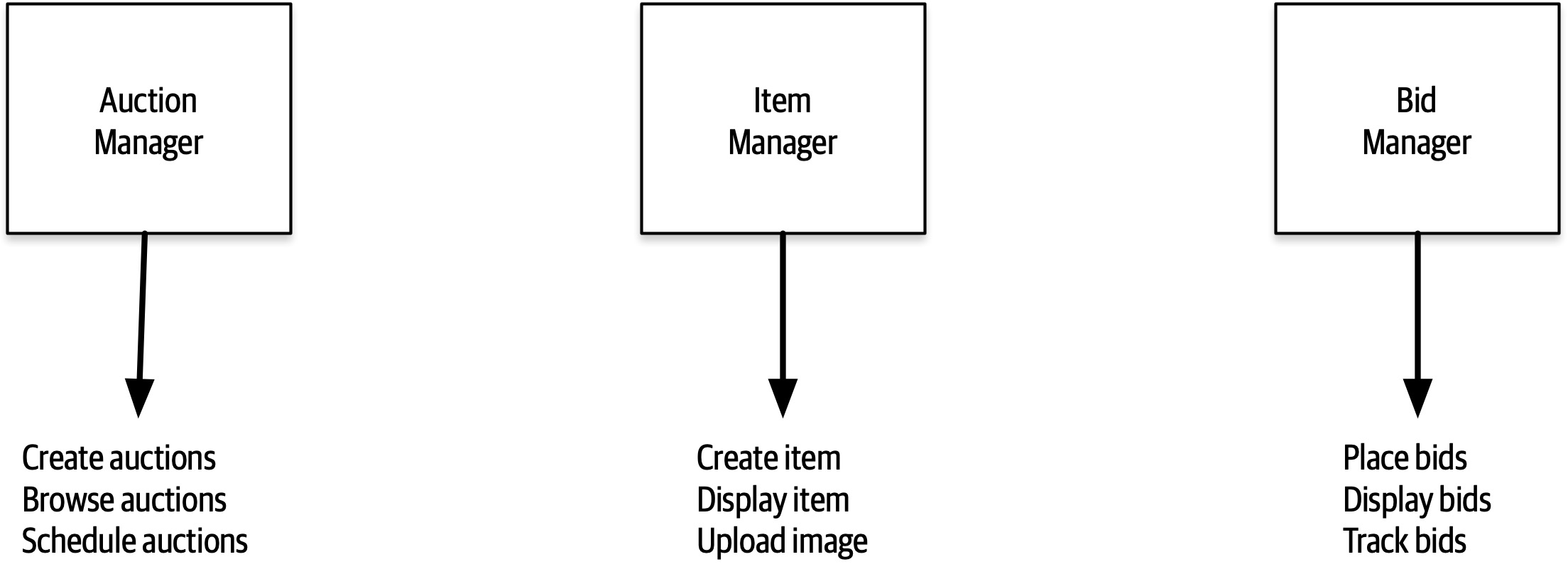
Figure 8-9. Building an architecture as an object-relational mapping
In Figure 8-9, the architect has basically taken each entity identified in the requirements and made a Manager component based on that entity.
Actor/Actions approach
The actor/actions approach became popular in conjunction with particular software development processes, especially more formal processes that favor a significant portion of upfront design. It is still popular and works well when the requirements feature distinct roles and the kinds of actions they can perform. This style of component decomposition works well for all types of systems, monolithic or distributed.
Event storming
Workflow approach
Case Study: Going, Going, Gone: Discovering Components
We can also identify a starting set of actions for each of these roles:
Bidder-
View live video stream, view live bid stream, place a bid
Auctioneer-
Enter live bids into system, receive online bids, mark item as sold
System-
Start auction, make payment, track bidder activity
Given these actions, we can iteratively build a set of starter components for GGG; one such solution appears in Figure 8-10.
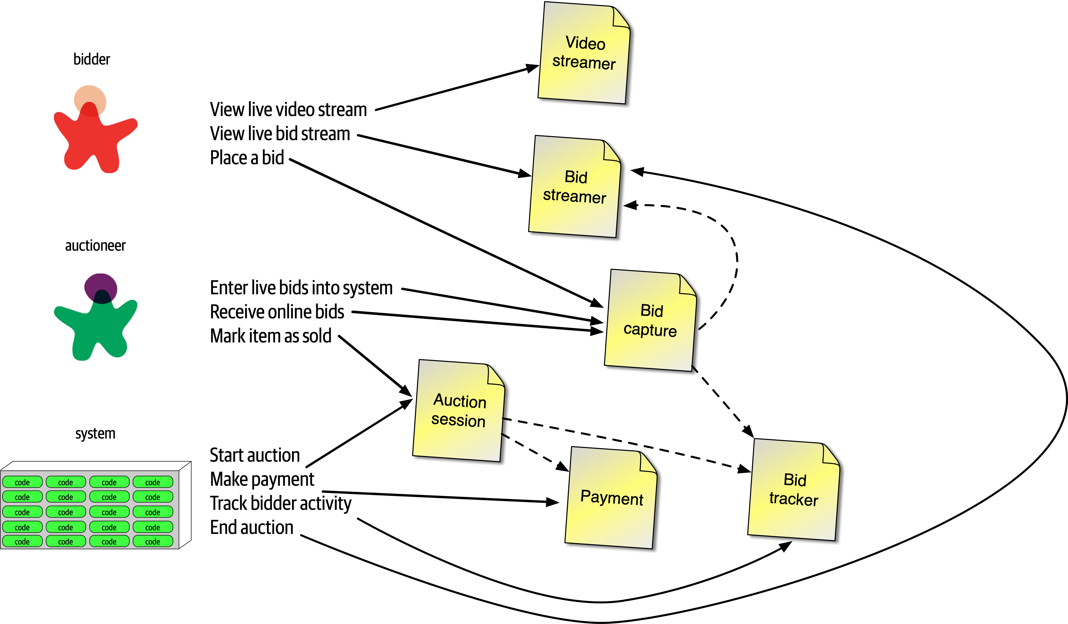
Figure 8-10. Initial set of components for Going, Going, Gone
In Figure 8-10, each of the roles and actions maps to a component, which in turn may need to collaborate on information. These are the components we identified for this solution:
VideoStreamer-
Streams a live auction to users.
BidStreamer-
Streams bids as they occur to the users. Both
Video StreamerandBid Streameroffer read-only views of the auction to the bidder. BidCapture-
This component captures bids from both the auctioneer and bidders.
BidTracker-
Tracks bids and acts as the system of record.
AuctionSession-
Starts and stops an auction. When the bidder ends the auction, performs the payment and resolution steps, including notifying bidders of ending.
Payment-
Third-party payment processor for credit card payments.
Referring to the component identification flow diagram in Figure 8-8, after the initial identification of components, the architect next analyzes architecture characteristics to determine if that will change the design. For this system, the architect can definitely identify different sets of architecture characteristics. For example, the current design features a BidCapture component to capture bids from both bidders and the auctioneer, which makes sense functionally: capturing bids from anyone can be handled the same. However, what about architecture characteristics around bid capture? The auctioneer doesn’t need the same level of scalability or elasticity as potentially thousands of bidders.
Bid Capture component into Bid Capture and Auctioneer Capture so that each of the two components can support differing architecture characteristics. 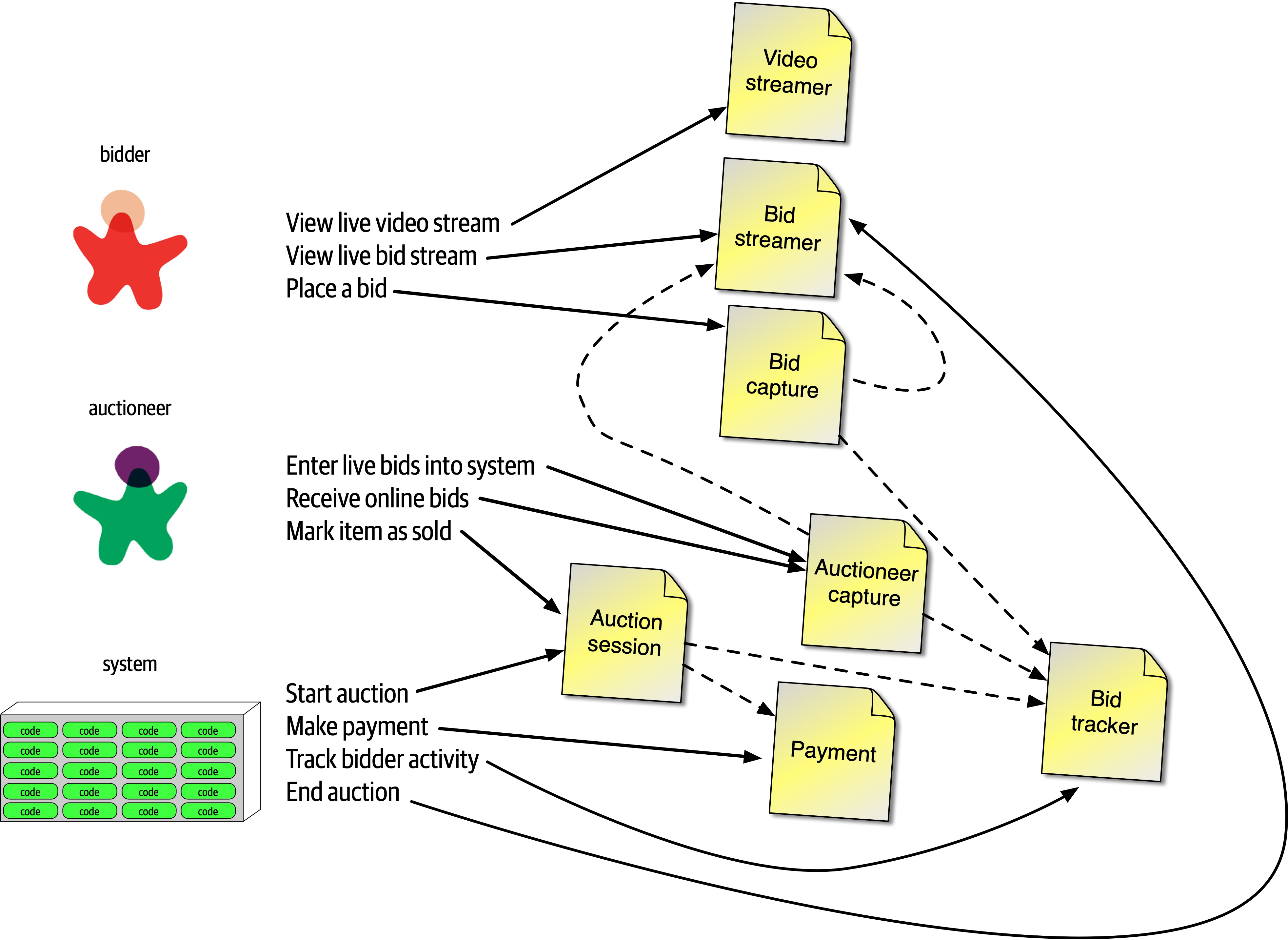
Figure 8-11. Incorporating architecture characteristics into GGG component design
In Figure 8-11, the architect creates a new component for Auctioneer Capture and updates information links to both Bid Streamer (so that online bidders see the live bids) and Bid Tracker, which is managing the bid streams. Note that Bid Tracker is now the component that will unify the two very different information streams: the single stream of information from the auctioneer and the multiple streams from bidders.
The design shown in Figure 8-11 isn’t likely the final design. More requirements must be uncovered (how do people register, administration functions around payment, and so on). However, this example provides a good starting point to start iterating further on the design.
This is one possible set of components to solve the GGG problem—but it’s not necessarily correct, nor is it the only one. Few software systems have only one way that developers can implement them; every design has different sets of trade-offs. As an architect, don’t obsess over finding the one true design, because many will suffice (and less likely overengineered). Rather, try to objectively assess the trade-offs between different design decisions, and choose the one that has the least worst set of trade-offs.
Architecture Quantum Redux: Choosing Between Monolithic Versus Distributed Architectures
Each architecture style offers a variety of trade-offs, covered in Part II. However, the fundamental decision rests on how many quanta the architecture discovers during the design process. If the system can manage with a single quantum (in other words, one set of architecture characteristics), then a monolith architecture offers many advantages. On the other hand, differing architecture characteristics for components, as illustrated in the GGG component analysis, requires a distributed architecture to accommodate differing architecture characteristics. For example, the VideoStreamer and BidStreamer both offer read-only views of the auction to bidders. From a design standpoint, an architect would rather not deal with read-only streaming mixed with high-scale updates. Along with the aforementioned differences between bidder and auctioneer, these differing characteristics lead an architect to choose a distributed architecture.
The ability to determine a fundamental design characteristic of architecture (monolith versus distributed) early in the design process highlights one of the advantages of using the architecture quantum as a way of analyzing architecture characteristics scope and coupling.
Part II. Architecture Styles
The difference between an architecture style and an architecture pattern can be confusing. We define an architecture style as the overarching structure of how the user interface and backend source code are organized (such as within layers of a monolithic deployment or separately deployed services) and how that source code interacts with a datastore. Architecture patterns, on the other hand, are lower-level design structures that help form specific solutions within an architecture style (such as how to achieve high scalability or high performance within a set of operations or between sets of services).
Understanding architecture styles occupies much of the time and effort for new architects because they share importance and abundance. Architects must understand the various styles and the trade-offs encapsulated within each to make effective decisions; each architecture style embodies a well-known set of trade-offs that help an architect make the right choice for a particular business problem.
Chapter 9. Foundations
Architecture styles, sometimes called architecture patterns, describe a named relationship of components covering a variety of architecture characteristics.
Fundamental Patterns
Big Ball of Mud
Architects refer to the absence of any discernible architecture structure as a Big Ball of Mud, named after
A Big Ball of Mud is a haphazardly structured, sprawling, sloppy, duct-tape-and-baling-wire, spaghetti-code jungle. These systems show unmistakable signs of unregulated growth, and repeated, expedient repair. Information is shared promiscuously among distant elements of the system, often to the point where nearly all the important information becomes global or duplicated.
The overall structure of the system may never have been well defined.
If it was, it may have eroded beyond recognition. Programmers with a shred of architectural sensibility shun these quagmires. Only those who are unconcerned about architecture, and, perhaps, are comfortable with the inertia of the day-to-day chore of patching the holes in these failing dikes, are content to work on such systems.
Brian Foote and Joseph Yoder
In modern terms, a big ball of mud might describe a simple scripting application with event handlers wired directly to database calls, with no real internal structure. Many trivial applications start like this then become unwieldy as they continue to grow.
In general, architects want to avoid this type of architecture at all costs. The lack of structure makes change increasingly difficult. This type of architecture also suffers from problems in deployment, testability, scalability, and performance.
The client (whose name is withheld for obvious reasons) created a Java-based web application as quickly as possible over several years. The technical visualization1 shows their architectural coupling: each dot on the perimeter of the circle represents a class, and each line represents connections between the classes, where bolder lines indicate stronger connections. In this code base, any change to a class makes it difficult to predict rippling side effects to other classes, making change a terrifying affair.

Figure 9-1. A Big Ball of Mud architecture visualized from a real code base
Unitary Architecture
When software originated, there was only the computer, and software ran on it.
Few unitary architectures exist outside embedded systems and other highly constrained environments. Generally, software systems tend to grow in functionality over time, requiring separation of concerns to maintain operational architecture characteristics, such as performance and scale.
Client/Server
Desktop + database server
Browser + web server
Three-tier
Monolithic Versus Distributed Architectures
In this book we will describe in detail the following architecture styles:
- Monolithic
- Layered architecture (Chapter 10)
-
Pipeline architecture (Chapter 11)
-
Microkernel architecture (Chapter 12)
- Distributed
-
-
Service-based architecture (Chapter 13)
-
Event-driven architecture (Chapter 14)
-
Space-based architecture (Chapter 15)
-
Service-oriented architecture (Chapter 16)
-
Microservices architecture (Chapter 17)
-
Distributed architecture styles, while being much more powerful in terms of performance, scalability, and availability than monolithic architecture styles, have significant trade-offs for this power.
Fallacy #1: The Network Is Reliable
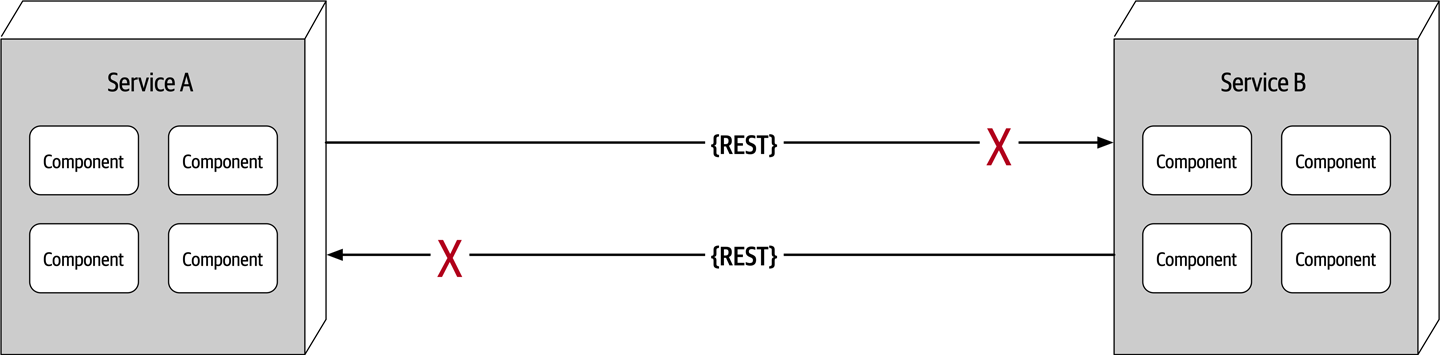
Figure 9-2. The network is not reliable
Developers and architects alike assume that the network is reliable, but it is not.
Service B may be totally healthy, but Service A cannot reach it due to a network problem; or even worse, Service A made a request to Service B to process some data and does not receive a response because of a network issue.Fallacy #2: Latency Is Zero
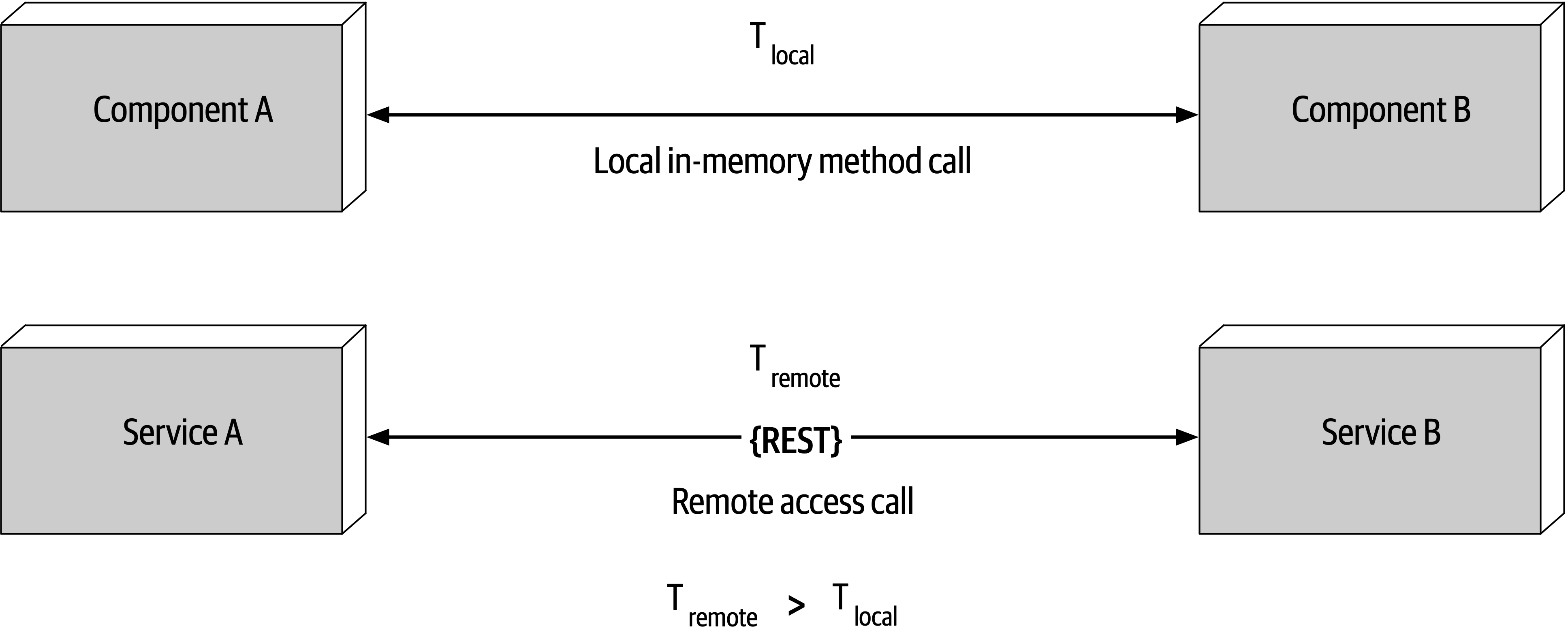
Figure 9-3. Latency is not zero
t_local) is measured in nanoseconds or microseconds.t_remote) is measured in milliseconds. Therefore, t_remote will always be greater that t_local. Latency in any distributed architecture is not zero, yet most architects ignore this fallacy, insisting that they have fast networks. Ask yourself this question: do you know what the average round-trip latency is for a RESTful call in your production environment? Is it 60 milliseconds? Is it 500 milliseconds?Fallacy #3: Bandwidth Is Infinite
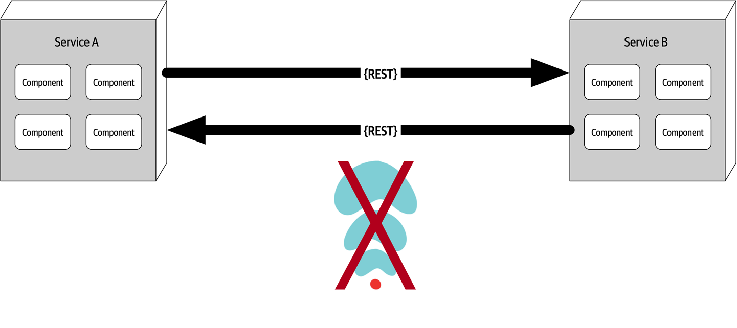
Figure 9-4. Bandwidth is not infinite
Bandwidth is usually not a concern in monolithic architectures, because once processing goes into a monolith, little or no bandwidth is required to process that business request.
To illustrate the importance of this fallacy, consider the two services shown in Figure 9-4. Let’s say the lefthand service manages the wish list items for the website, and the righthand service manages the customer profile. Whenever a request for a wish list comes into the lefthand service, it must make an interservice call to the righthand customer profile service to get the customer name because that data is needed in the response contract for the wish list, but the wish list service on the lefthand side doesn’t have the name. The customer profile service returns 45 attributes totaling 500 kb to the wish list service, which only needs the name (200 bytes).
-
Create private RESTful API endpoints
-
Use field selectors in the contract
- UseGraphQL to decouple contracts
-
Use value-driven contracts with consumer-driven contracts (CDCs)
-
Use internal messaging endpoints
Regardless of the technique used, ensuring that the minimal amount of data is passed between services or systems in a distributed architecture is the best way to address this fallacy.
Fallacy #4: The Network Is Secure
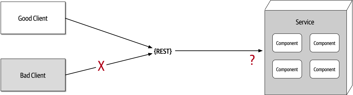
Figure 9-5. The network is not secure
Most architects and developers get so comfortable using virtual private networks (VPNs),
Fallacy #5: The Topology Never Changes
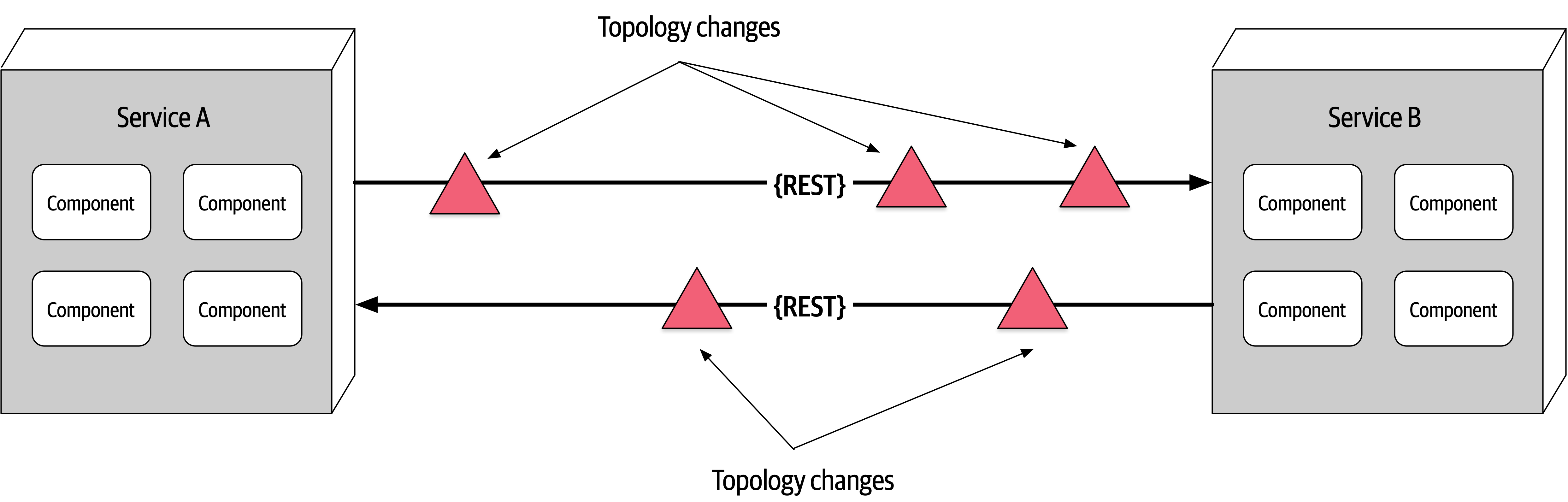
Figure 9-6. The network topology always changes
This fallacy refers to the overall network topology, including all of the routers, hubs, switches, firewalls, networks, and appliances used within the overall network.
Suppose an architect comes into work on a Monday morning, and everyone is running around like crazy because services keep timing out in production. The architect works with the teams, frantically trying to figure out why this is happening. No new services were deployed over the weekend. What could it be? After several hours the architect discovers that a minor network upgrade happened at 2 a.m. that morning. This supposedly “minor” network upgrade invalidated all of the latency assumptions, triggering timeouts and circuit breakers.
Architects must be in constant communication with operations and network administrators to know what is changing and when so that they can make adjustments accordingly to reduce the type of surprise previously described. This may seem obvious and easy, but it is not. As a matter of fact, this fallacy leads directly to the next fallacy.
Fallacy #6: There Is Only One Administrator

Figure 9-7. There are many network administrators, not just one
Fallacy #7: Transport Cost Is Zero
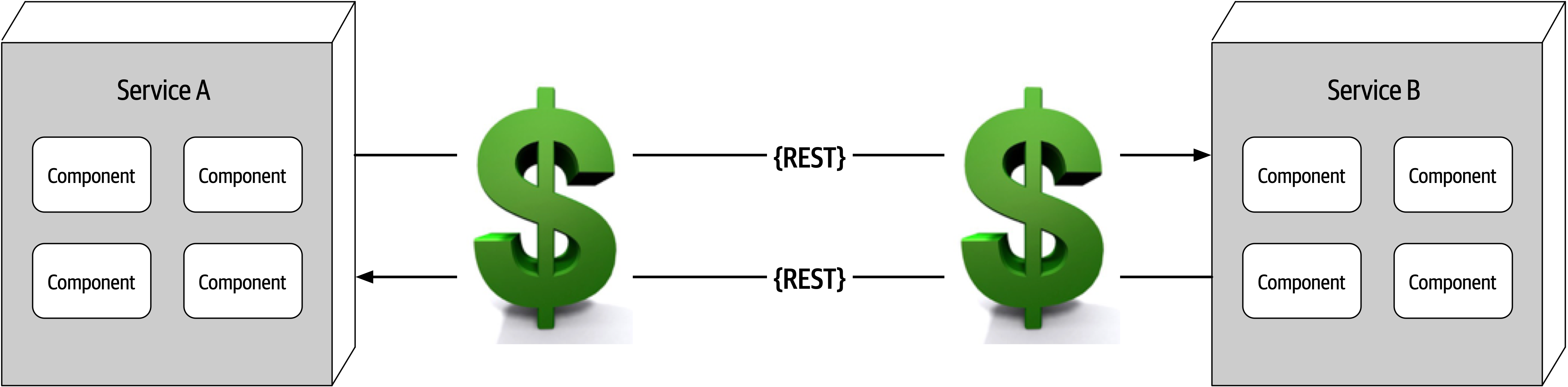
Figure 9-8. Remote access costs money
Many software architects confuse this fallacy for latency (“Fallacy #2: Latency Is Zero”). Transport cost
Whenever embarking on a distributed architecture, we encourage architects to analyze the current server and network topology with regard to capacity, bandwidth, latency, and security zones to not get caught up in the trap of surprise with this fallacy.
Fallacy #8: The Network Is Homogeneous
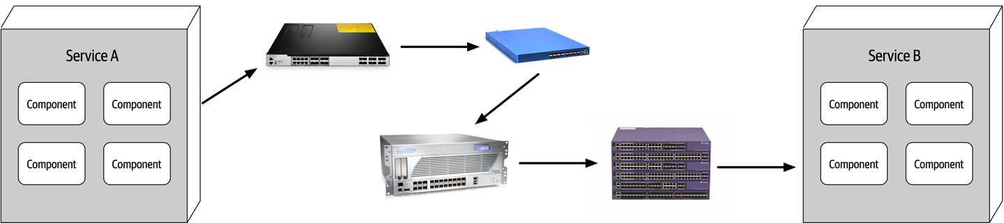
Figure 9-9. The network is not homogeneous
Other Distributed Considerations
Distributed logging
Distributed transactions
Architects and developers take transactions for granted in a monolithic architecture world because they are so straightforward and easy to manage.
commits and rollbacks executed from persistence frameworks leverage ACID (atomicity, consistency, isolation, durability) transactions to guarantee that the data is updated in a correct way to ensure high data consistency and integrity.Contract maintenance and versioning
Chapter 10. Layered Architecture Style
The layered architecture, also known as the n-tiered architecture style, is one of the most common architecture styles.
Topology
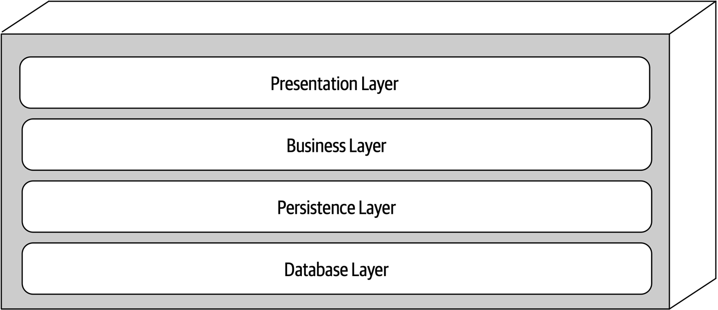
Figure 10-1. Standard logical layers within the layered architecture style
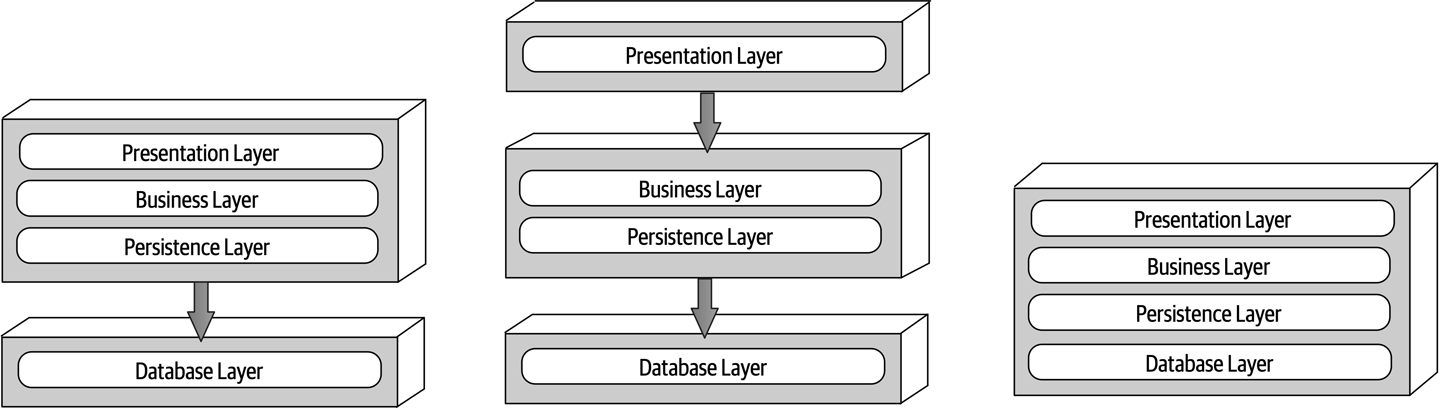
Figure 10-2. Physical topology (deployment) variants
Each layer of the layered architecture style has a specific role and responsibility within the architecture. For example, the presentation layer would be responsible for handling all user interface and browser communication logic, whereas the business layer would be responsible for executing specific business rules associated with the request. Each layer in the architecture forms an abstraction around the work that needs to be done to satisfy a particular business request. For example, the presentation layer doesn’t need to know or worry about how to get customer data; it only needs to display that information on a screen in a particular format. Similarly, the business layer doesn’t need to be concerned about how to format customer data for display on a screen or even where the customer data is coming from; it only needs to get the data from the persistence layer, perform business logic against the data (such as calculating values or aggregating data), and pass that information up to the presentation layer.
Layers of Isolation
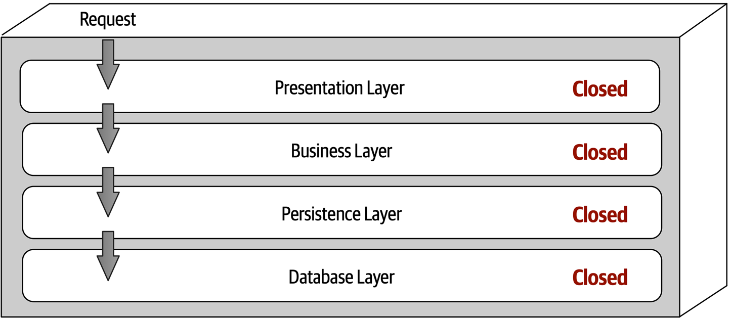
Figure 10-3. Closed layers within the layered architecture
Notice that in Figure 10-3 it would be much faster and easier for the presentation layer to access the database directly for simple retrieval requests, bypassing any unnecessary layers (what used to be known in the early 2000s as the fast-lane reader pattern).
The layers of isolation concept means that changes made in one layer of the architecture generally don’t impact or affect components in other layers, providing the contracts between those layers remain unchanged. Each layer is independent of the other layers, thereby having little or no knowledge of the inner workings of other layers in the architecture. However, to support layers of isolation, layers involved with the major flow of the request necessarily have to be closed. If the presentation layer can directly access the persistence layer, then changes made to the persistence layer would impact both the business layer and the presentation layer, producing a very tightly coupled application with layer interdependencies between components. This type of architecture then becomes very brittle, as well as difficult and expensive to change.
Adding Layers
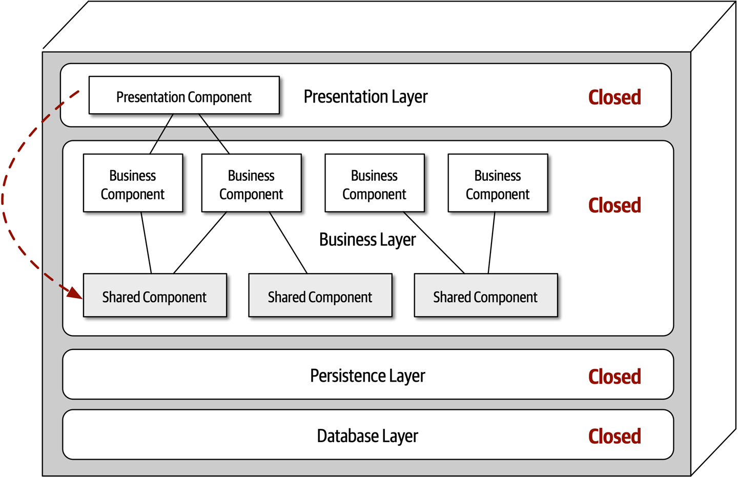
Figure 10-4. Shared objects within the business layer
One way to architecturally mandate this restriction is to add to the architecture a new services layer containing all of the shared business objects. Adding this new layer now architecturally restricts the presentation layer from accessing the shared business objects because the business layer is closed (see Figure 10-5). However, the new services
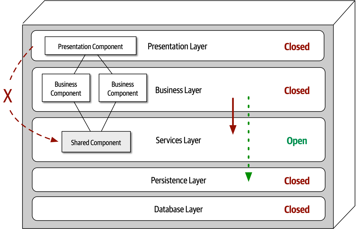
Figure 10-5. Adding a new services layer to the architecture
Leveraging the concept of open and closed layers helps define the relationship between architecture layers and request flows. It also provides developers with the necessary information and guidance to understand various layer access restrictions within the architecture. Failure to document or properly communicate which layers in the architecture are open and closed (and why) usually results in tightly coupled and brittle architectures that are very difficult to test, maintain, and deploy.
Other Considerations
The layered architecture makes for a good starting point for most applications when it is not known yet exactly which architecture style will ultimately be used.
Every layered architecture will have at least some scenarios that fall into the architecture sinkhole anti-pattern. The key to determining whether the architecture sinkhole anti-pattern is at play is to analyze the percentage of requests that fall into this category. The 80-20 rule is usually a good practice to follow. For example, it is acceptable if only 20 percent of the requests are sinkholes. However, if 80 percent of the requests are sinkholes, it a good indicator that the layered architecture is not the correct architecture style for the problem domain. Another approach to solving the architecture sinkhole anti-pattern is to make all the layers in the architecture open, realizing, of course, that the trade-off is increased difficulty in managing change within the architecture.
Why Use This Architecture Style
As applications using the layered architecture style grow, characteristics like maintainability, agility, testability, and deployability are adversely affected. For this reason, large applications and systems using the layered architecture might be better suited for other, more modular architecture styles.
Architecture Characteristics Ratings
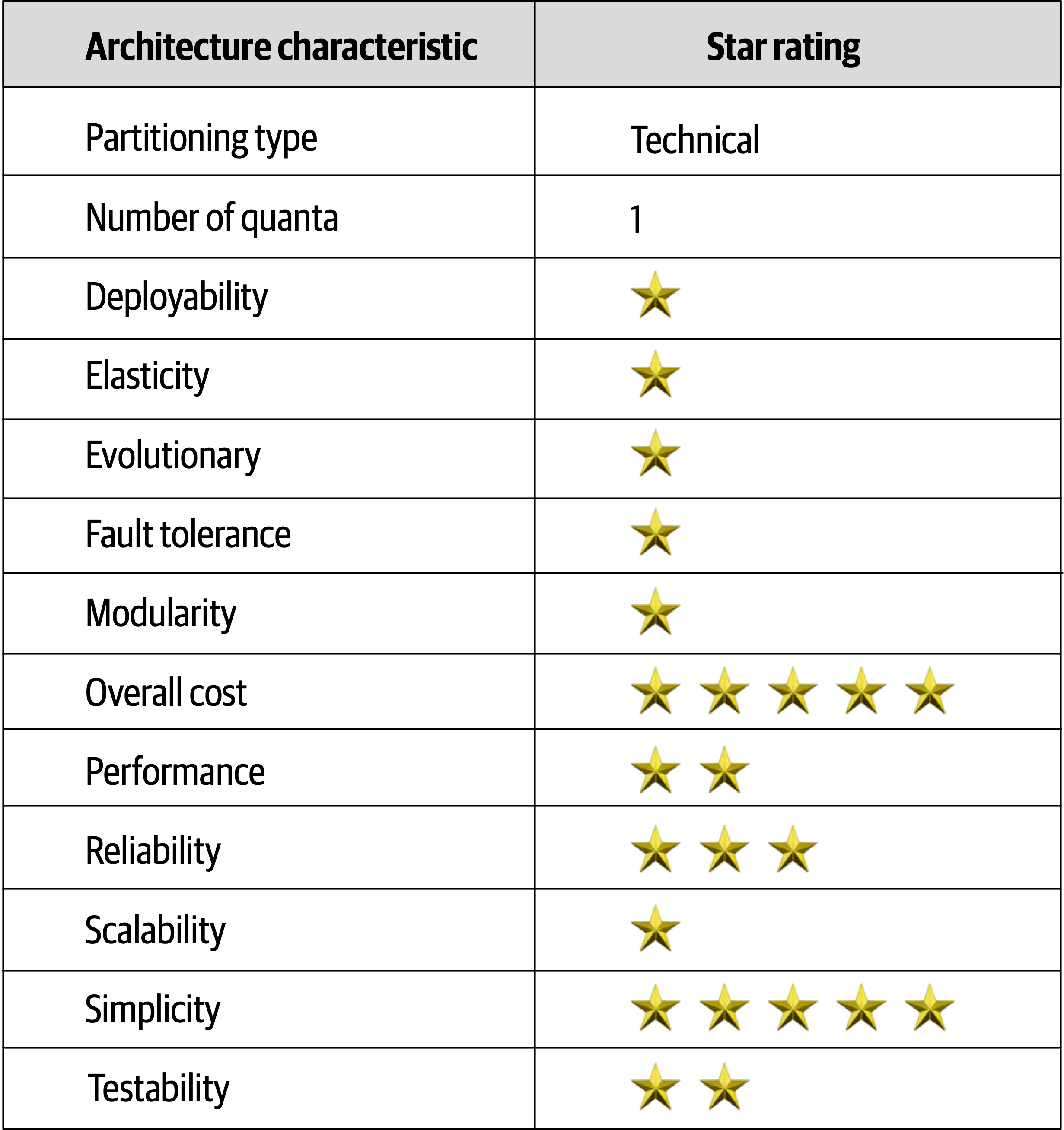
Figure 10-6. Layered architecture characteristics ratings
Overall cost and simplicity are the primary strengths of the layered architecture style.
Chapter 11. Pipeline Architecture Style
One of the fundamental styles in software architecture that appears again and again is the pipeline architecture (also known as the pipes and filters architecture).
Developers in many functional programming languages will see parallels between language constructs and elements of this architecture. In fact, many tools that utilize the MapReduce programming model follow this basic topology. While these examples show a low-level implementation of the pipeline architecture style, it can also be used for higher-level business applications.
Topology
The
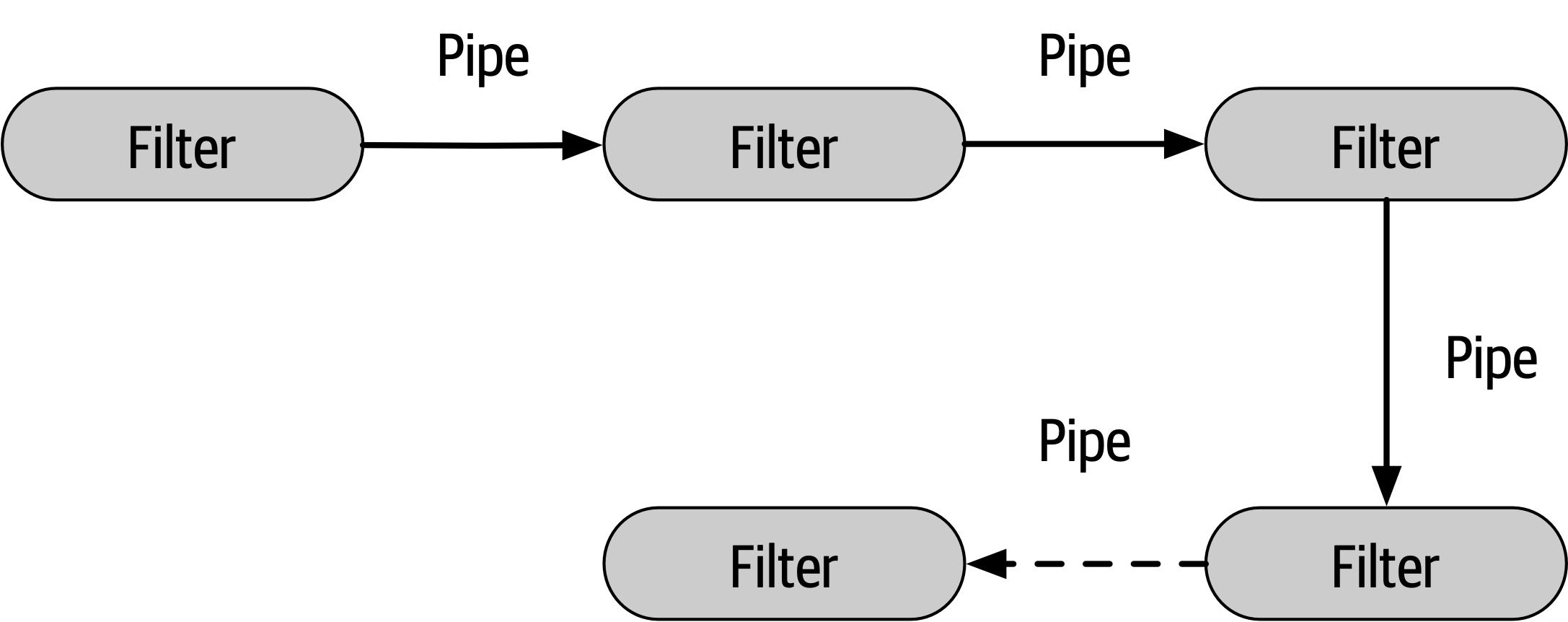
Figure 11-1. Basic topology for pipeline architecture
The pipes and filters coordinate in a specific fashion, with pipes forming one-way communication between filters, usually in a point-to-point fashion.
Pipes
Pipes in this architecture form the communication channel between filters. Each pipe is typically unidirectional and point-to-point (rather than broadcast) for performance reasons, accepting input from one source and always directing output to another. The payload carried on the pipes may be any data format, but architects favor smaller amounts of data to enable high performance.
Filters
Filters are self-contained, independent from other filters, and generally stateless. Filters should perform one task only. Composite tasks should be handled by a sequence of filters rather than a single one.
Four types of
- Producer
- The starting point of aprocess, outbound only, sometimes called the source.
- Transformer
- Accepts input, optionally performs a transformation on some or all of the data, then forwards it to the outbound pipe.Functional advocates will recognize this feature as map.
- Tester
- Accepts input, tests one or more criteria, then optionally produces output, based on the test.Functional programmers will recognize this as similar to reduce.
- Consumer
- The termination point for the pipeline flow.Consumers sometimes persist the final result of the pipeline process to a database, or they may display the final results on a user interface screen.
tr -cs A-Za-z'\n'|tr A-Z a-z|sort|uniq -c|sort -rn|sed${1}q
Even the designers of Unix shells are often surprised at the inventive uses developers have wrought with their simple but powerfully composite abstractions.
Example
To illustrate how the pipeline architecture can be used, consider the following example, as illustrated in Figure 11-2, where various service telemetry information is sent from services via streaming to Apache Kafka.
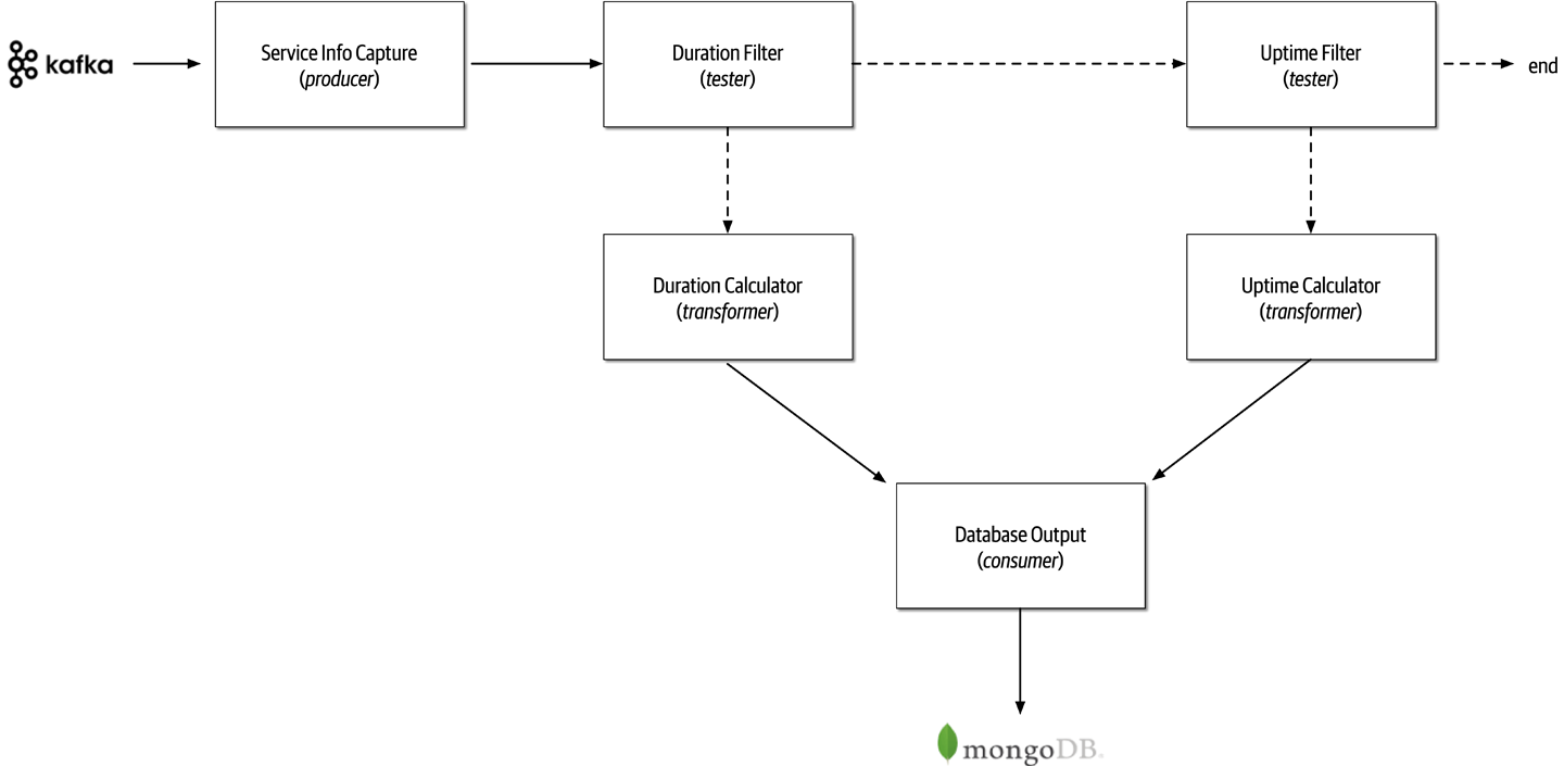
Figure 11-2. Pipeline architecture example
Notice in Figure 11-2 the use of the pipeline architecture style to process the different kinds of data streamed to Kafka.
Service Info Capture filter (producer filter) subscribes to the Kafka topic and receives service information. Duration Filter to determine whether the data captured from Kafka is related to the duration (in milliseconds) of the service request. Notice the separation of concerns between the filters; the Service Metrics Capture filter is only concerned about how to connect to a Kafka topic and receive streaming data, whereas the Duration Filter is only concerned about qualifying the data and optionally routing it to the next pipe. If the data is related to the duration (in milliseconds) of the service request, then the Duration Filter passes the data on to the Duration Calculator transformer filter.Uptime Filter tester filter to check if the data is related to uptime metrics. If it is not, then the pipeline ends—the data is of no interest to this particular processing flow. Otherwise, if it is uptime metrics, it then passes the data along to the Uptime Calculator to calculateDatabase Output consumer, which then persists the data in a Uptime Filter to pass the data on to another newly gathered metric, such as the database connection wait time.Architecture Characteristics Ratings
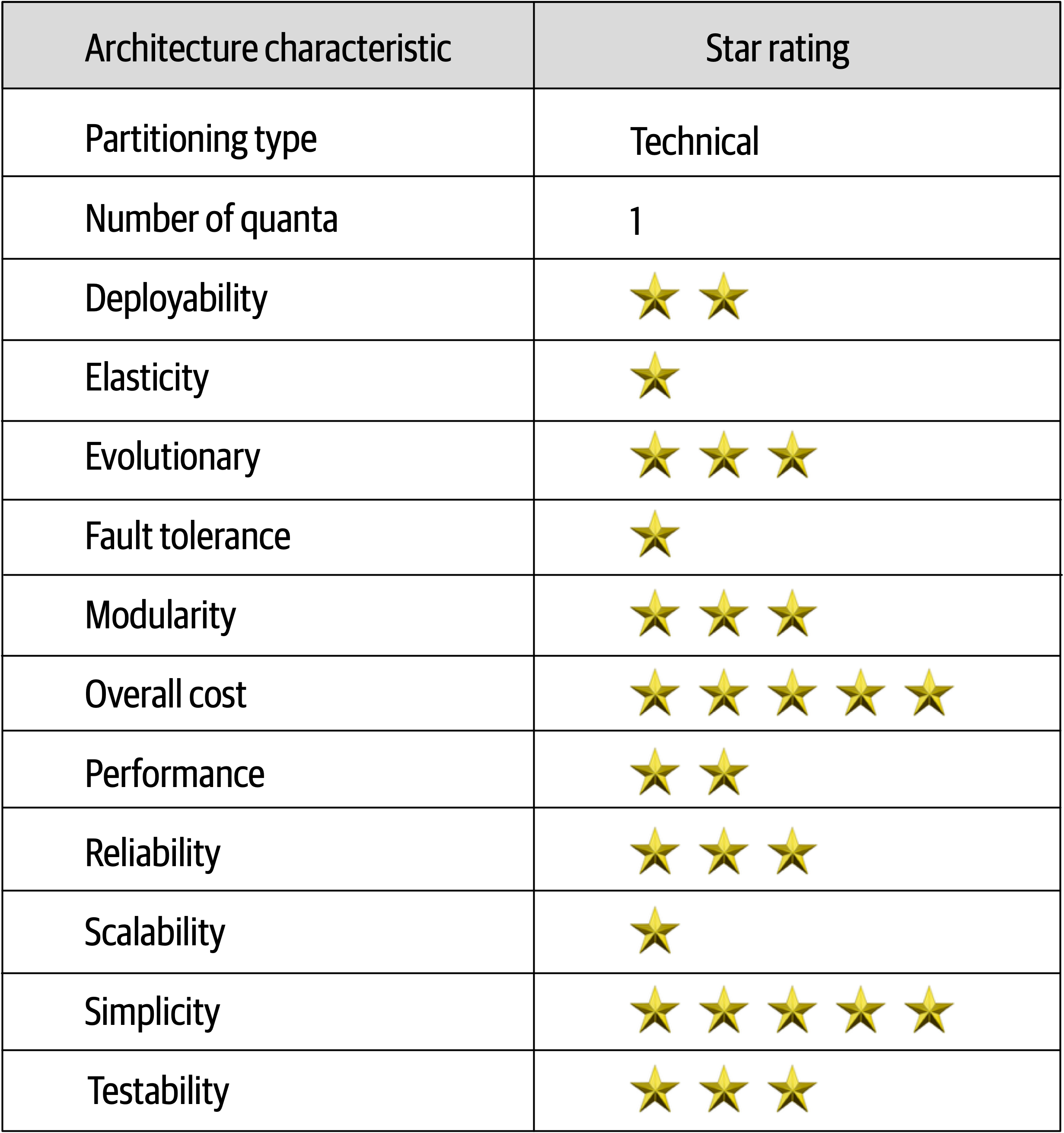
Figure 11-3. Pipeline architecture characteristics ratings
The pipeline architecture style is a technically partitioned architecture due to the partitioning of application logic into filter types (producer, tester, transformer, and consumer).
Duration Calculator can be modified to change the duration calculation without impacting any other filter. Deployability and testability, while only around average, rate slightly higher than the
Chapter 12. Microkernel Architecture Style
The microkernel architecture style (also referred to as the plug-in architecture) was coined several
Topology
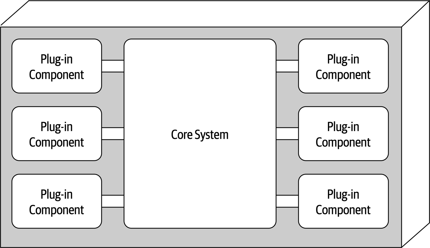
Figure 12-1. Basic components of the microkernel architecture style
Core System
The core system is formally defined as the minimal functionality required to run the system.
publicvoidassessDevice(StringdeviceID){if(deviceID.equals("iPhone6s")){assessiPhone6s();}elseif(deviceID.equals("iPad1"))assessiPad1();}elseif(deviceID.equals("Galaxy5"))assessGalaxy5();}else......}}
Rather than placing all this client-specific customization in the core system with lots of cyclomatic complexity, it is much better to create a separate plug-in component for each electronic device being assessed. Not only do specific client plug-in components isolate independent device logic from the rest of the processing flow, but they also allow for expandability. Adding a new electronic device to assess is simply a matter of adding a new plug-in component and updating the registry. With the microkernel architecture style, assessing an electronic device only requires the core system to locate and invoke the corresponding device plug-ins as illustrated in this revised source code:
publicvoidassessDevice(StringdeviceID){Stringplugin=pluginRegistry.get(deviceID);Class<?>theClass=Class.forName(plugin);Constructor<?>constructor=theClass.getConstructor();DevicePlugindevicePlugin=(DevicePlugin)constructor.newInstance();DevicePlugin.assess();}
In this example all of the complex rules and instructions for assessing a particular electronic device are self-contained in a standalone, independent plug-in component that can be generically executed from the core system.
Payment Processing is the domain service representing the core system. Each payment method (credit card, PayPal, store credit, gift card, and purchase order) would be separate plug-in components specific to the payment domain. In all of these cases, it is typical for the entire monolithic application to share a single database.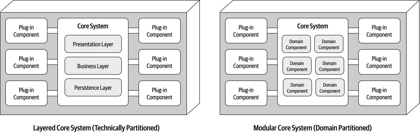
Figure 12-2. Variations of the microkernel architecture core system
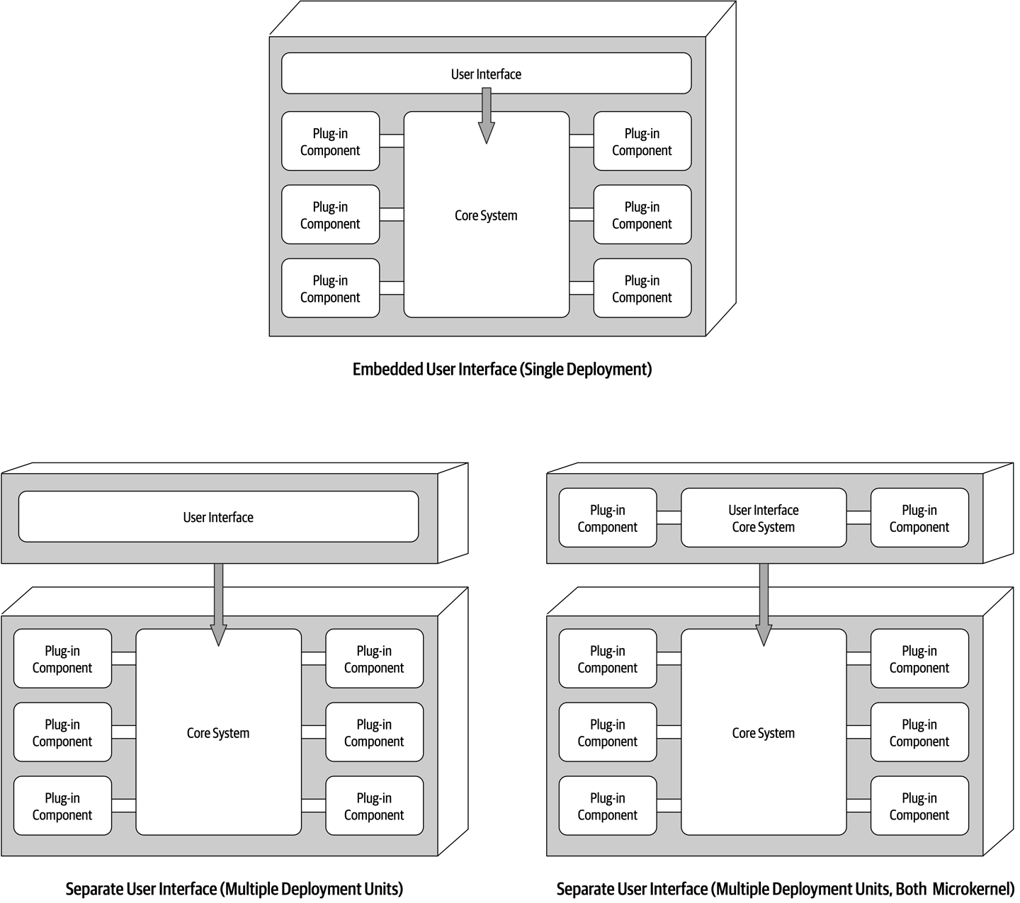
Figure 12-3. User interface variants
Plug-In Components
Plug-in components are
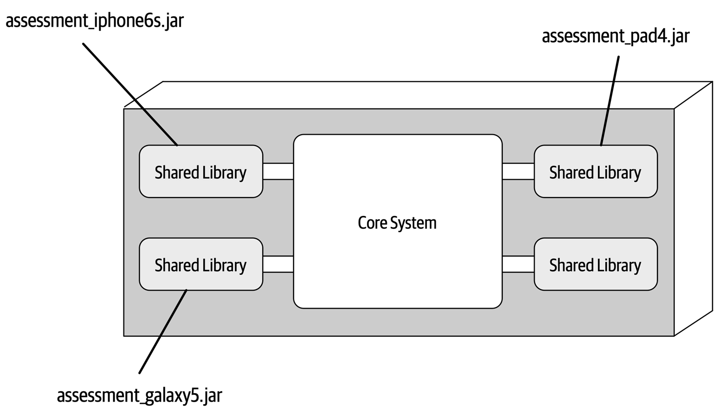
Figure 12-4. Shared library plug-in implementation
Alternatively, an easier approach shown in Figure 12-5 is to implement each plug-in component as a separate namespace or package name within the same code base or IDE project.
app.plug-in.<domain>.<context>. For example, consider the namespace app.plugin.assessment.iphone6s. The second node (plugin) makes it clear this component is a plug-in and therefore should strictly adhere to the basic rules regarding plug-in components (namely, that they are self-contained and separate from other plug-ins). The third node describes the domain (in this case, assessment), thereby allowing plug-in components to be organized and grouped by a common purpose. The fourth node (iphone6s) describes the specific context for the plug-in, making it easy to locate the specific device plug-in for modification or testing.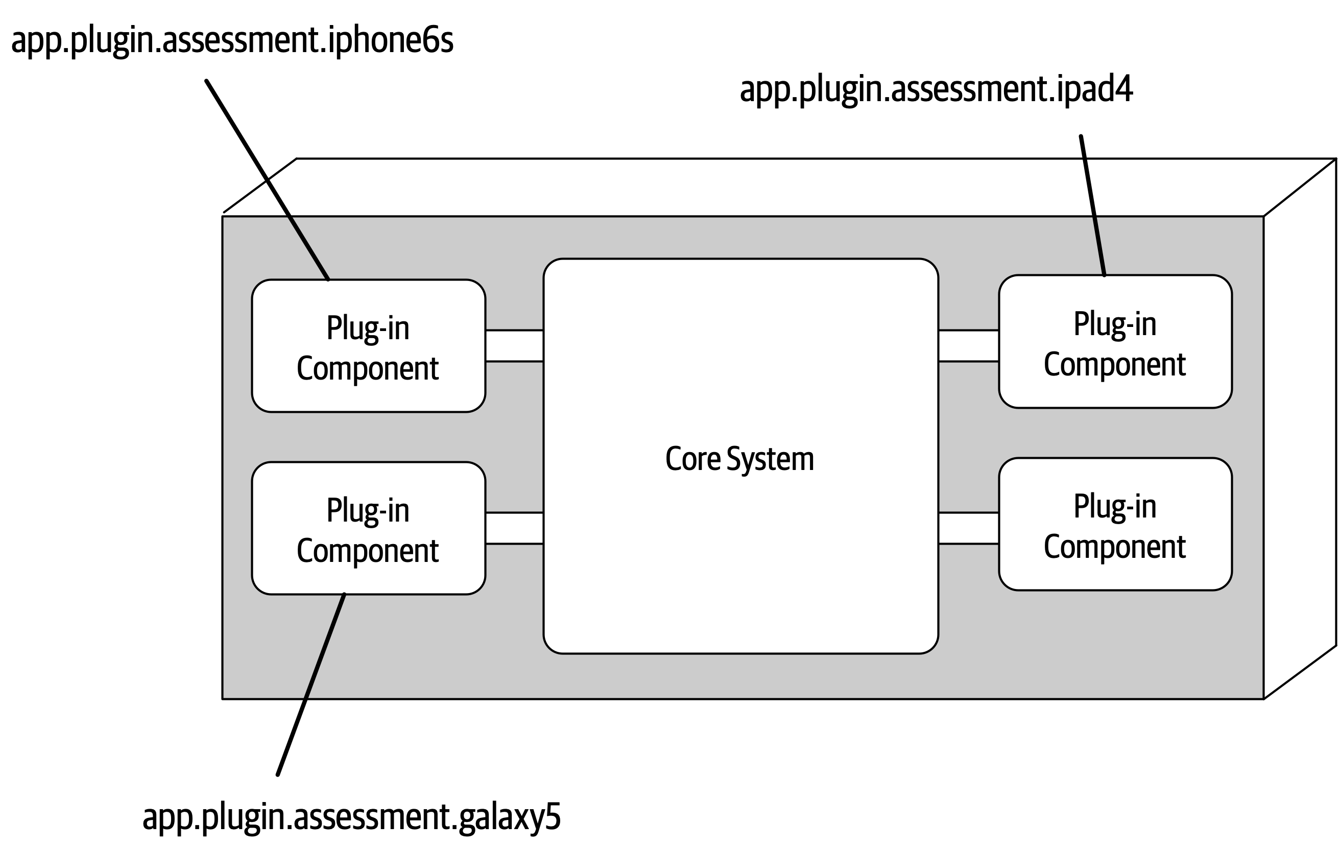
Figure 12-5. Package or namespace plug-in implementation
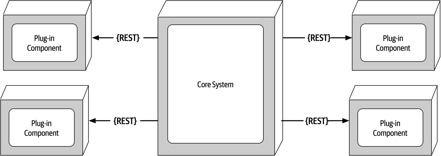
Figure 12-6. Remote plug-in access using REST
The benefits of the remote access approach to accessing plug-in components implemented as individual services is that it provides better overall component decoupling, allows for better scalability and throughput, and allows for runtime changes without any special frameworks like OSGi, Jigsaw, or Prism. It also allows for asynchronous communications to plug-ins, which, depending on the scenario, could significantly improve overall user responsiveness. Using the electronics recycling example, rather than having to wait for the electronic device assessment to run, the core system could make an asynchronous request to kick off an assessment for a particular device. When the assessment completes, the plug-in can notify the core system through another asynchronous messaging channel, which in turn would notify the user that the assessment is complete.
With these benefits comes trade-offs. Remote plug-in access turns the microkernel architecture into a distributed architecture rather than a monolithic one, making it difficult to implement and deploy for most third-party on-prem products.
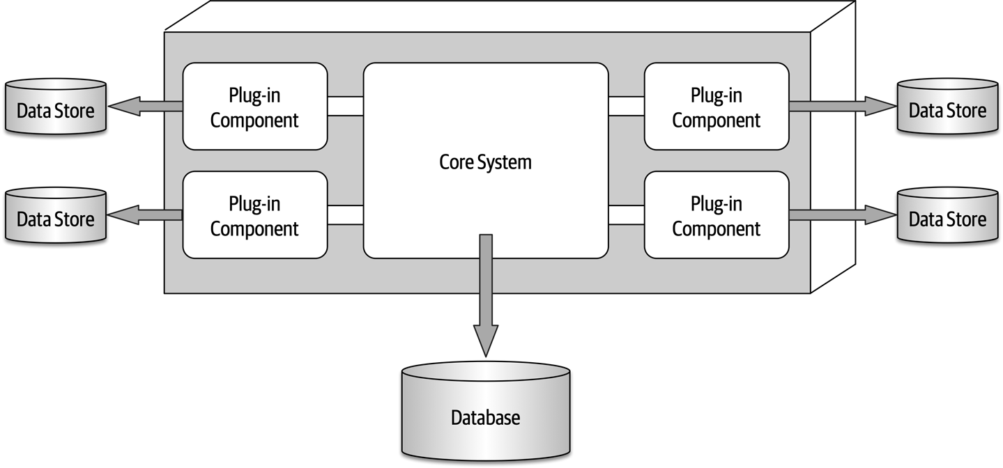
Figure 12-7. Plug-in components can own their own data store
Registry
The core system needs to know about which plug-in modules are available and how to get to them.
Map<String,String>registry=newHashMap<String,String>();static{//point-to-point access exampleregistry.put("iPhone6s","Iphone6sPlugin");//messaging exampleregistry.put("iPhone6s","iphone6s.queue");//restful exampleregistry.put("iPhone6s","https://atlas:443/assess/iphone6s");}
Contracts
Plug-in contracts can be implemented in XML, JSON, or even objects passed back and forth between the plug-in and the core system. In keeping with the electronics recycling application, the following contract (implemented as a standard Java interface named AssessmentPlugin) defines the overall behavior (assess(), register(), and deregister()), along with the corresponding output data expected from the plug-in component (AssessmentOutput):
publicinterfaceAssessmentPlugin{publicAssessmentOutputassess();publicStringregister();publicStringderegister();}publicclassAssessmentOutput{publicStringassessmentReport;publicBooleanresell;publicDoublevalue;publicDoubleresellPrice;}
In this contract example, the device assessment plug-in is expected to return the assessment report as a formatted string; a resell flag (true or false) indicating whether this device can be resold on a third-party market or safely disposed of; and finally, if it can be resold (another form of recycling), what the calculated value is of the item and what the recommended resell price should be.
Notice the roles and responsibility model between the core system and the plug-in component in this example, specifically with the assessmentReport field. It is not the responsibility of the core system to format and understand the details of the assessment report, only to either print it out or display it to the user.
Examples and Use Cases
Claims processing is a very complicated process. Each jurisdiction has different rules and regulations for what is and isn’t allowed in an insurance claim. For example, some jurisdictions (e.g., states) allow free windshield replacement if your windshield is damaged by a rock, whereas other states do not. This creates an almost infinite set of conditions for a standard claims process.
Most insurance claims applications leverage large and complex rules engines to handle much of this complexity. However, these rules engines can grow into a complex big ball of mud where changing one rule impacts other rules, or making a simple rule change requires an army of analysts, developers, and testers to make sure nothing is broken by a simple change. Using the microkernel architecture pattern can solve many of these issues.
The claims rules for each jurisdiction can be contained in separate standalone plug-in components (implemented as source code or a specific rules engine instance accessed by the plug-in component). This way, rules can be added, removed, or changed for a particular jurisdiction without impacting any other part of the system. Furthermore, new jurisdictions can be added and removed without impacting other parts of the system. The core system in this example would be the standard process for filing and processing a claim, something that doesn’t change often.
Another example of a large and complex business application that can leverage the microkernel architecture is tax preparation software. For example, the United States has a basic two-page tax form called the 1040 form that contains a summary of all the information needed to calculate a person’s tax liability. Each line in the 1040 tax form has a single number that requires many other forms and worksheets to arrive at that single number (such as gross income). Each of these additional forms and worksheets can be implemented as a plug-in component, with the 1040 summary tax form being the core system (the driver). This way, changes to tax law can be isolated to an independent plug-in component, making changes easier and less risky.
Architecture Characteristics Ratings
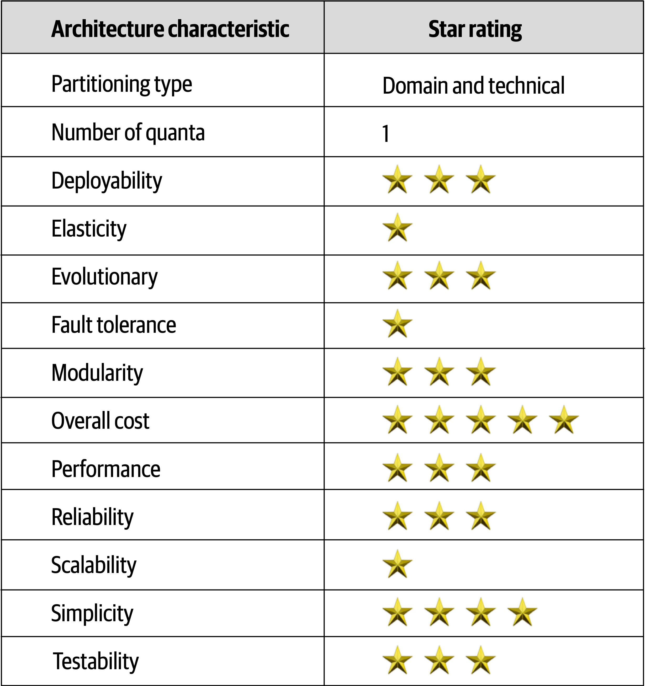
Figure 12-8. Microkernel architecture characteristics ratings
Similar to the layered architecture style, simplicity and overall cost are the main strengths of the microkernel architecture style, and scalability, fault tolerance, and extensibility its main weaknesses.
Chapter 13. Service-Based Architecture Style
Service-based architecture
Topology
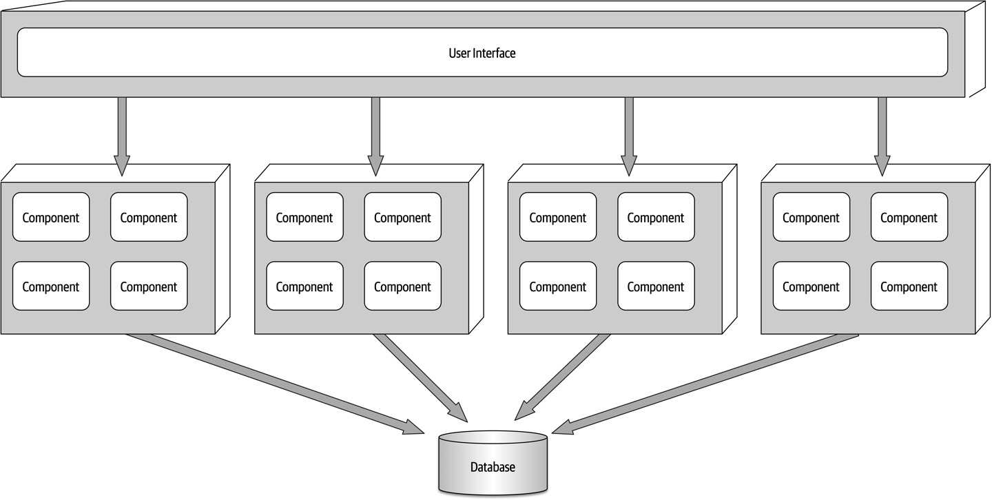
Figure 13-1. Basic topology of the service-based architecture style
Services within this architecture style are typically coarse-grained “portions of an application” (usually called domain services) that are independent and separately deployed.
In most cases there is only a single instance of each domain service within a service-based architecture. However, based on scalability, fault tolerance, and throughput needs, multiple instances of a domain service can certainly exist. Multiple instances of a service usually require some sort of load-balancing capability between the user interface and the domain service so that the user interface can be directed to a healthy and available service instance.
Topology Variants
Many topology variants exist within the service-based architecture style, making this perhaps one of the most flexible architecture styles.
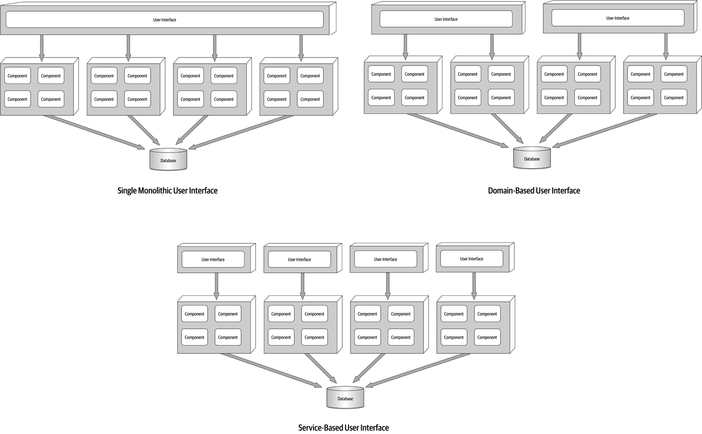
Figure 13-2. User interface variants
Similarly, opportunities may exist to break apart a single monolithic database into separate databases, even going as far as domain-scoped databases matching each domain service (similar to microservices).
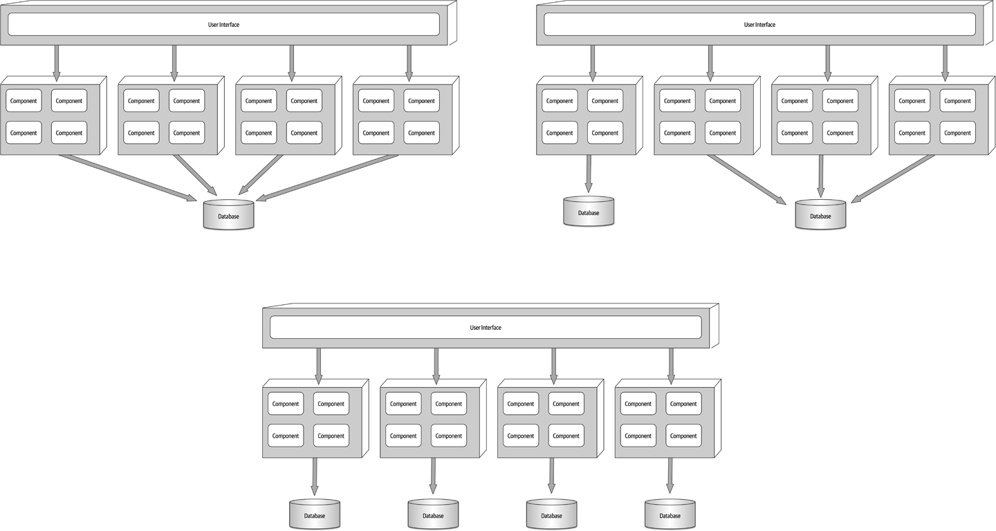
Figure 13-3. Database variants
Finally, it is also possible to add an API layer
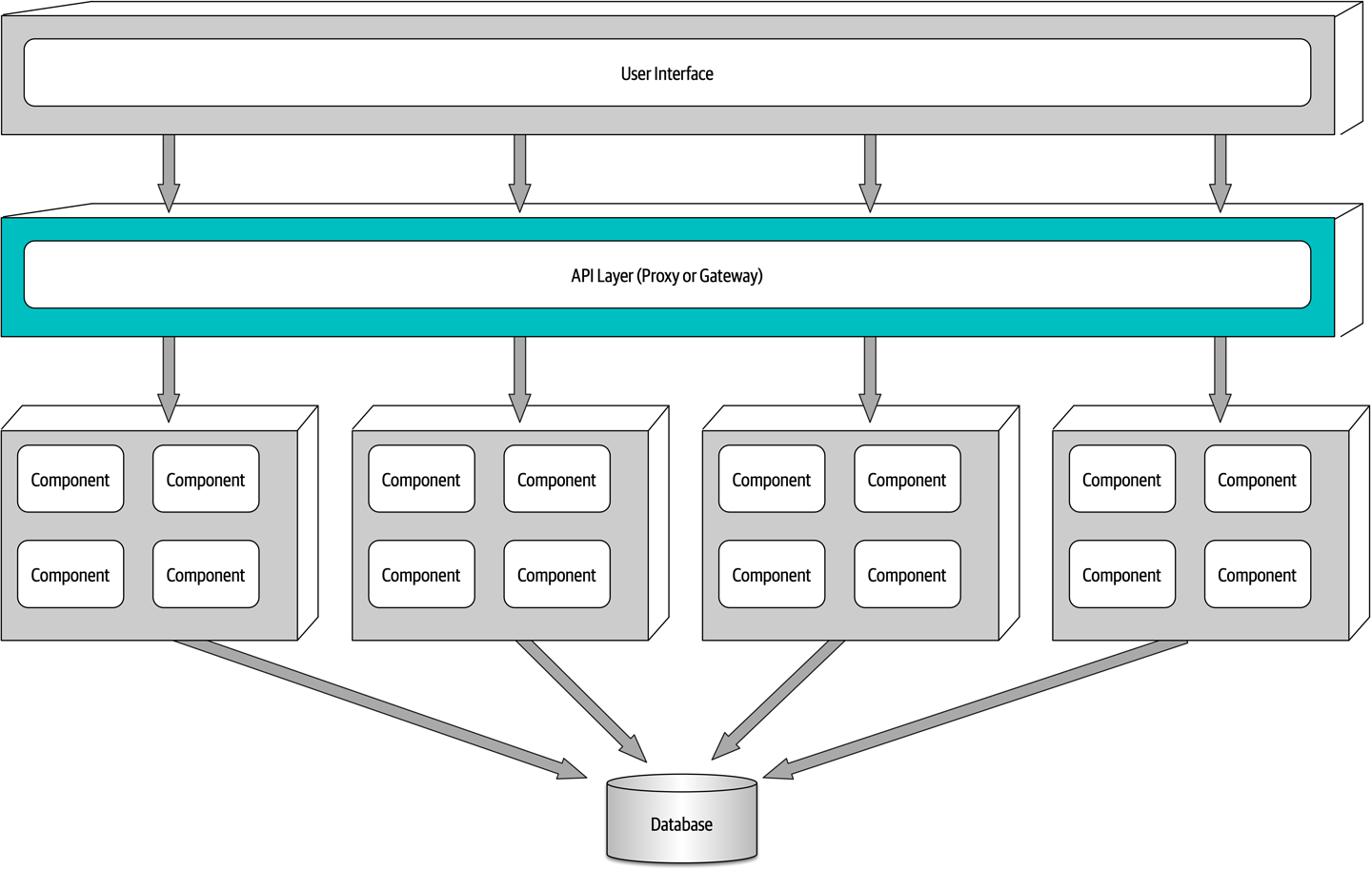
Figure 13-4. Adding an API layer between the user interface and domain services
Service Design and Granularity
Because domain services in a service-based architecture are generally coarse-grained, each domain
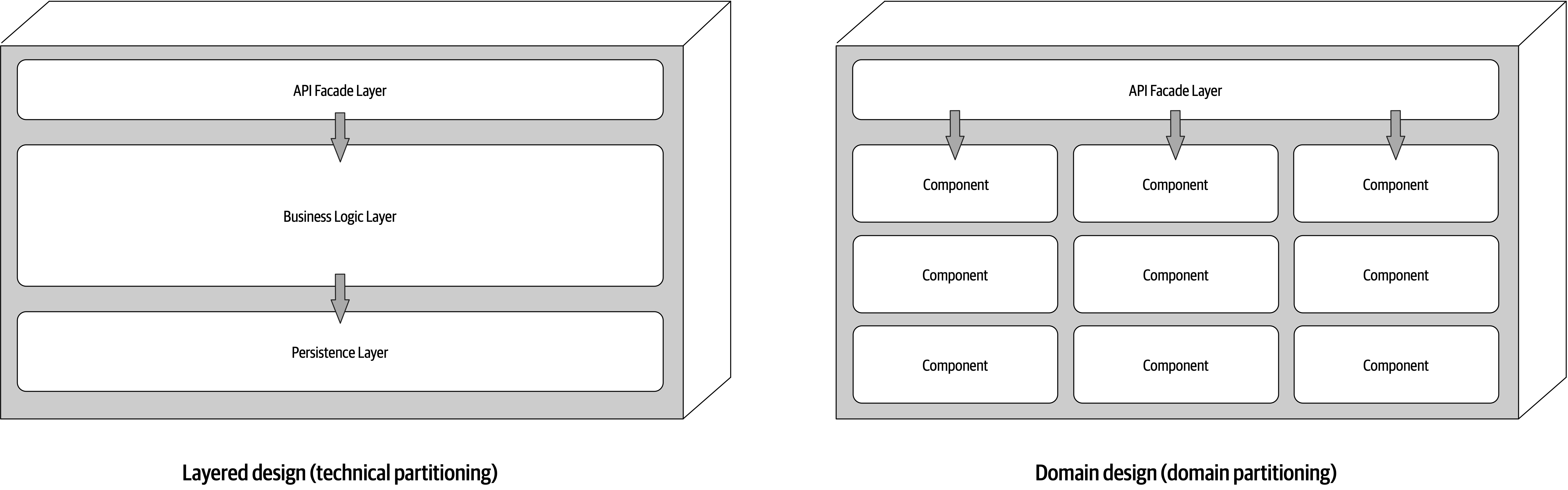
Figure 13-5. Domain service design variants
Regardless of the service design, a domain service must contain some sort of API access facade that the user interface interacts with to execute some sort of business functionality. The API access facade typically takes on the responsibility of orchestrating the business request from the user interface. For example, consider a business request from the user interface to place an order (also known as catalog checkout). This single request, received by the API access facade within the OrderService domain service, internally orchestrates the single business request: place the order, generate an order ID, apply the payment, and update the product inventory for each product ordered. In the microservices architecture style, this would likely involve the orchestration of many separately deployed remote single-purpose services to complete the request. This difference between internal class-level orchestration and external service orchestration points to one of the many significant differences between service-based architecture and microservices in terms of granularity.
Because domain services are coarse-grained, regular ACID (atomicity, consistency, isolation, durability) database transactions involving database commits and rollbacks are used to ensure database integrity within a single domain service.
To illustrate this point, consider the example of a catalog checkout process within a service-based architecture. Suppose the customer places an order and the credit card used for payment has expired. Since this is an atomic transaction within the same service, everything added to the database can be removed using a rollback and a notice sent to the customer stating that the payment cannot be applied. Now consider this same process in a microservices architecture with smaller fine-grained services. First, the OrderPlacement service would accept the request, create the order, generate an order ID, and insert the order into the order tables. Once this is done, the order service would then make a remote call to the PaymentService, which would try to apply the payment. If the payment cannot be applied due to an expired credit card, then the order cannot be placed and the data is in an inconsistent state (the order information has already been inserted but has not been approved). In this case, what about the inventory for that order? Should it be marked as ordered and decremented? What if the inventory is low and another customer wishes to purchase the item? Should that new customer be allowed to buy it, or should the reserved inventory be reserved for the customer trying to place the order with an expired credit card? These are just a few of the questions that would need to be addressed when orchestrating a business process with multiple finer-grained services.
OrderService would require testing the entire coarse-grained service (including payment processing), whereas with microservices the same change would only impact a small OrderPlacement service (requiring no change to the PaymentService). Furthermore, because more code is being deployed, there is more risk with service-based architecture that something might break (including payment processing), whereas with microservices each service has a single responsibility, hence less chance of breaking other functionality when being changed.Database Partitioning
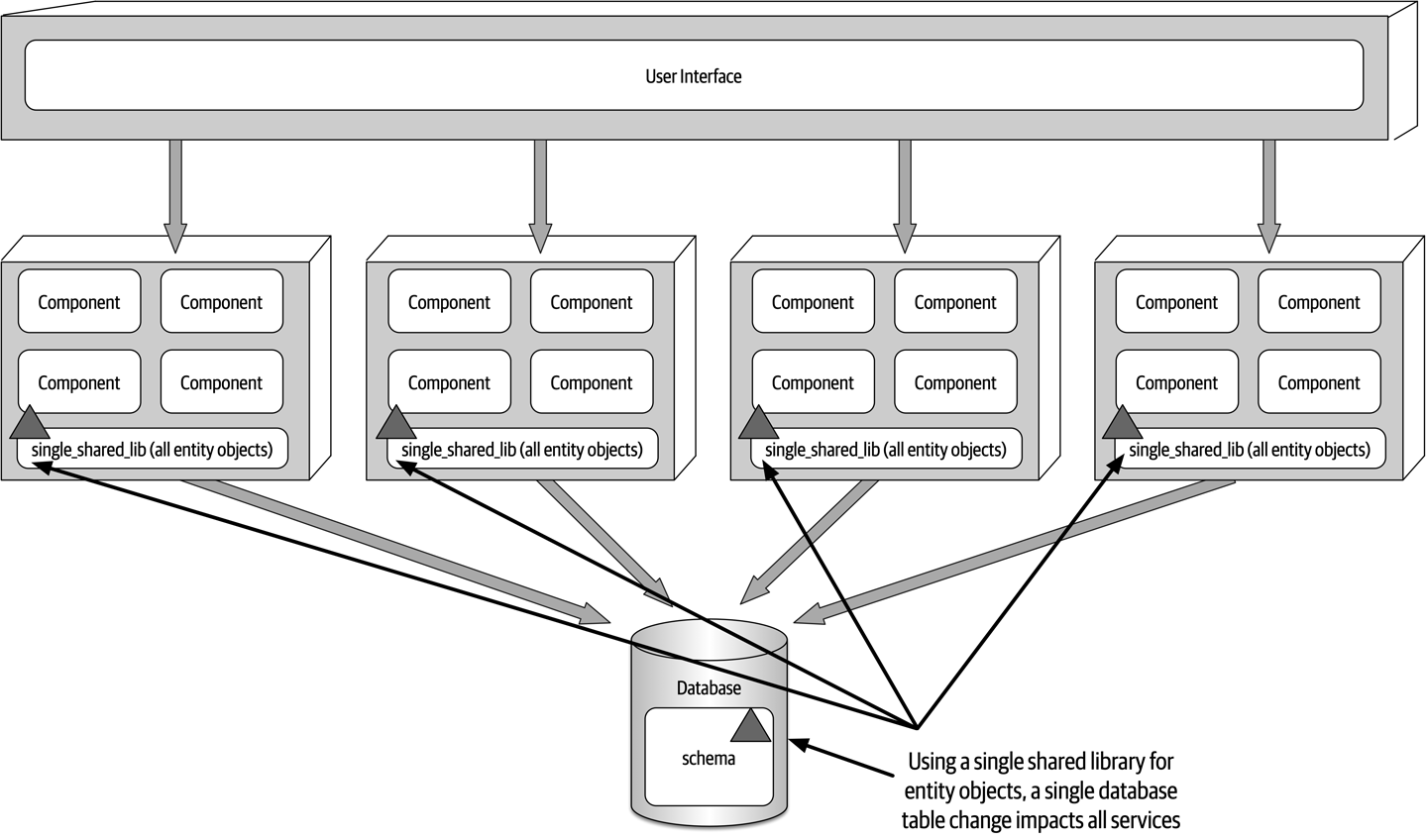
Figure 13-6. Using a single shared library for database entity objects
One way to mitigate the impact and risk of database changes is to logically partition the database and manifest the logical partitioning through federated shared libraries. Notice in Figure 13-7 that the database is logically partitioned into five separate domains (common, customer, invoicing, order, and tracking).
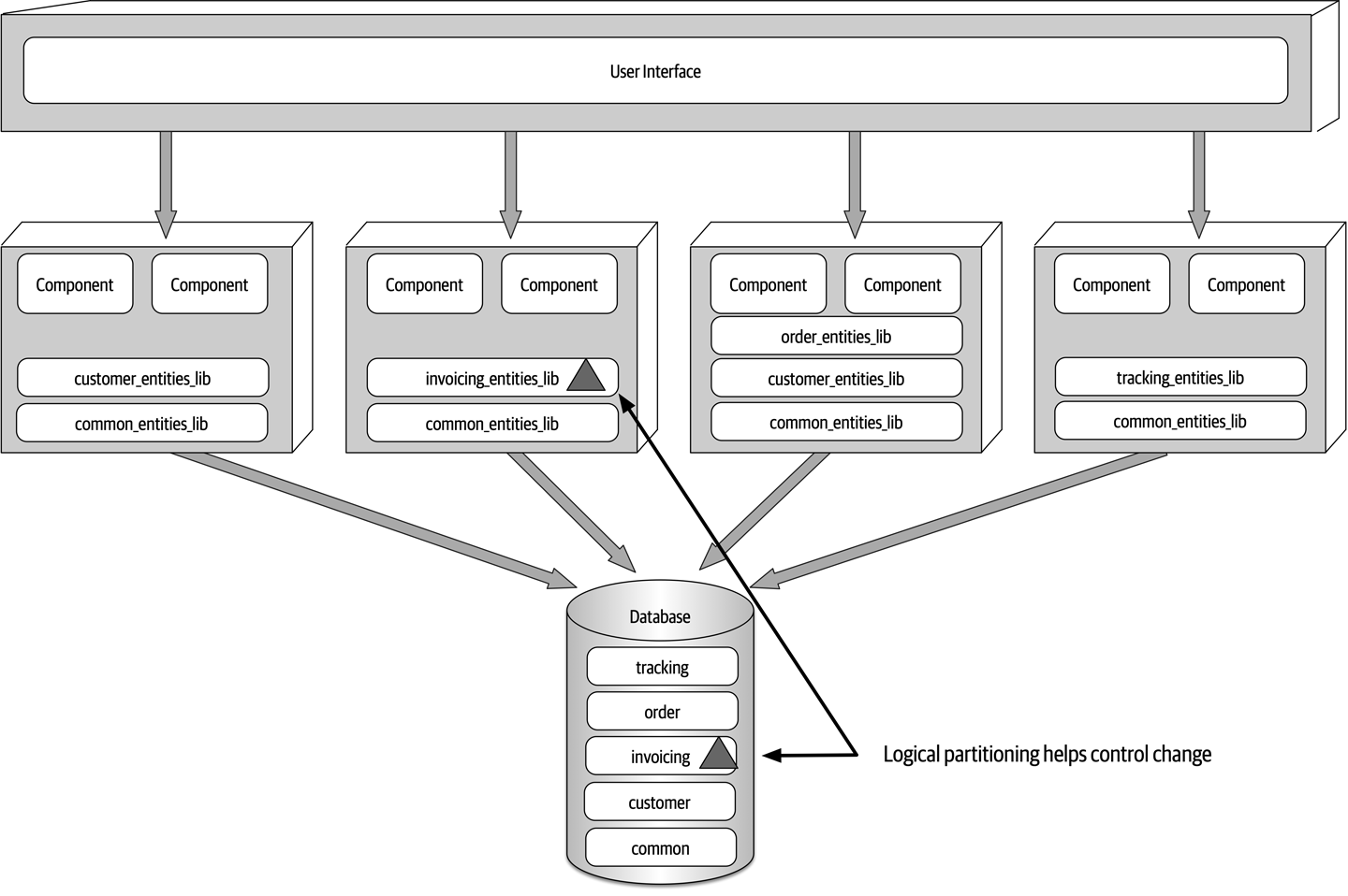
Figure 13-7. Using multiple shared libraries for database entity objects
common_entities_lib shared library used by all services. This is a relatively common occurrence. These tables are common to all services, and as such, changes to these tables require coordination of all services accessing the shared database. One way to mitigate changes to these tables (and corresponding entity objects) is to lock the common entity objects in the version control system and restrict change access to only the database team. This helps control change and emphasizes the significance of changes to the common tables used by all services. Tip
Make the logical partitioning in the database as fine-grained as possible while still maintaining well-defined data domains to better control database changes within a service-based architecture.
Example Architecture
Quoting service and ItemStatus service). The other services do not need to scale, and as such only require a single service instance. 
Figure 13-8. Electronics recycling example using service-based architecture
Also notice in Figure 13-8 how the user interface applications are federated into their respective domains: Customer Facing, Receiving, and Recycling and Accounting. This federation allows for fault tolerance of the user interface, scalability, and security (external customers have no network path to internal functionality). Finally, notice in this example that there are two separate physical databases: one for external customer-facing operations, and one for internal operations. This allows the internal data and operations to reside in a separate network zone from the external operations (denoted by the vertical line), providing much better security access restrictions and data protection. One-way access through the firewall allows internal services to access and update the customer-facing information, but not vice versa. Alternatively, depending on the database being used, internal table mirroring and table synchronization could also be used.
This example illustrates many of the benefits of the service-based architecture approach: scalability, fault tolerance, and security (data and functionality protection and access), in addition to agility, testability, and deployability. For example, the Assessment service is changed constantly to add assessment rules as new products are received. This frequent change is isolated to a single domain service, providing agility (the ability to respond quickly to change), as well as testability (the ease of and completeness of testing) and deployability (the ease, frequency, and risk of deployment).
Architecture Characteristics Ratings
Figure 13-9. Service-based architecture characteristics ratings
Service-based architecture is a domain-partitioned architecture, meaning that the structure is driven by the domain rather than a technical consideration (such as presentation logic or persistence logic).
Quoting and Item Status); and one for the internal operations of receiving, assessing, and recycling the electronic device. Notice that even though the internal operations quantum contains separately deployed services and two separate user interfaces, they all share the same database, making the internal operations portion of the application a single quantum. 
Figure 13-10. Separate quanta in a service-based architecture
Although service-based architecture doesn’t contain any five-star ratings, it nevertheless rates high (four stars) in many important and vital areas. Breaking
Receiving service in the electronic recycling application example), it doesn’t impact any of the other six services.Quoting and Item Status services need to scale to support high customer volumes, but the other operational services only require single instances, making it easier to support such things as single in-memory caching and database connection pooling.When to Use This Architecture Style
Service-based architecture is also a natural fit when doing domain-driven design. Because services are coarse-grained and domain-scoped, each domain fits nicely into a separately deployed domain service. Each service in service-based architecture encompasses a particular domain (such as recycling in the electronic recycling application), therefore compartmentalizing that functionality into a single unit of software, making it easier to apply changes to that domain.
Chapter 14. Event-Driven Architecture Style
The event-driven architecture style is a popular distributed asynchronous architecture style used to produce highly
Figure 14-1. Request-based model
A good example of the request-based model is a request from a customer to retrieve their order history for the past six months. Retrieving order history information is a data-driven, deterministic request made to the system for data within a specific context, not an event happening that the system must react to.
An event-based model, on the other hand, reacts to a particular situation and takes action based on that event. An example of an event-based model is submitting a bid for a particular item within an online auction. Submitting the bid is not a request made to the system, but rather an event that happens after the current asking price is announced. The system must respond to this event by comparing the bid to others received at the same time to determine who is the current highest bidder.
Topology
Broker Topology
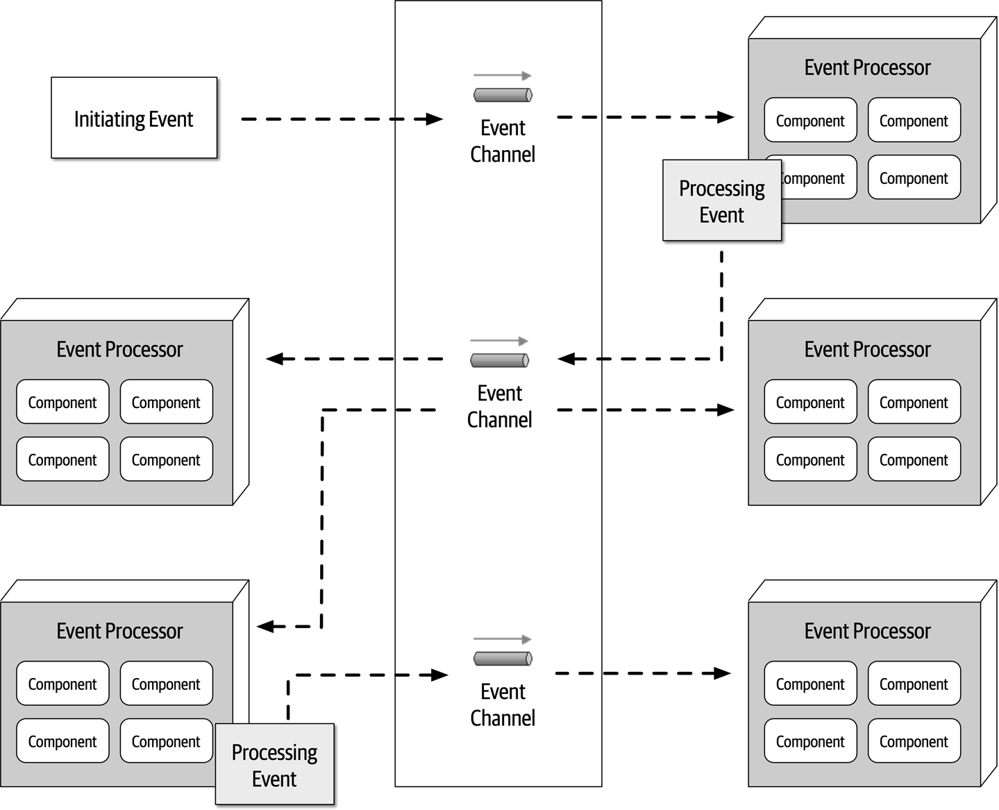
Figure 14-2. Broker topology
The event broker component is usually federated (meaning multiple domain-based clustered instances), where each federated broker contains all of the event channels used within the event flow for that particular domain.
Notification event processor would generate and send the email, then advertise that action to the rest of the system through a new processing event sent to a topic. However, in this case, no other event processors are listening for events on that topic, and as such the message simply goes away. 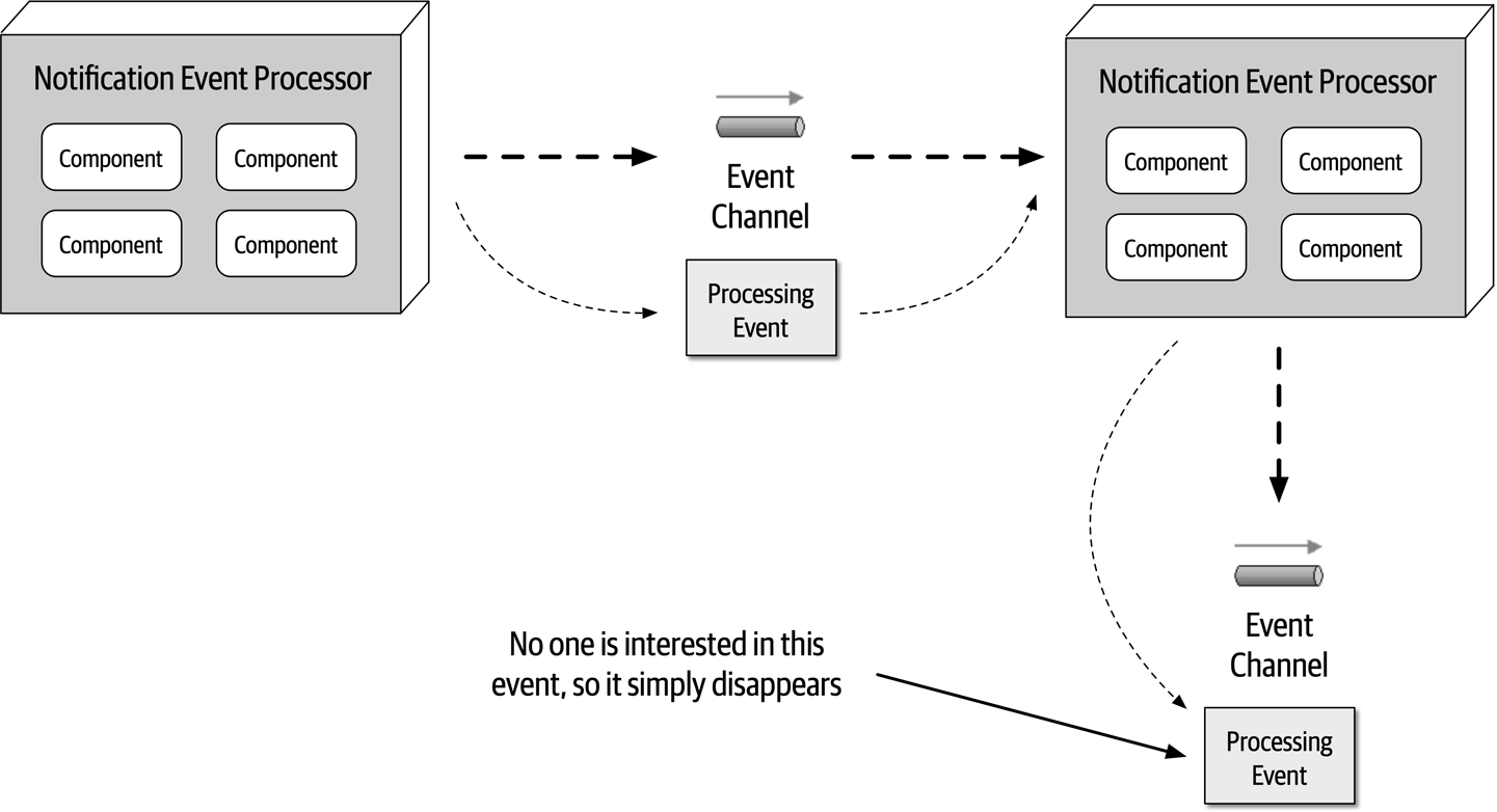
Figure 14-3. Notification event is sent but ignored
This is a good example of architectural extensibility.
OrderPlacement event processor receives the initiating event (PlaceOrder), inserts the order in a database table, and returns an order ID to the customer. It then advertises to the rest of the system that it created an order through an order-created processing event. Notice that three event processors are interested in that event: the Notification event processor, the Payment event processor, and the Inventory event processor. All three of these event processors perform their tasks in parallel.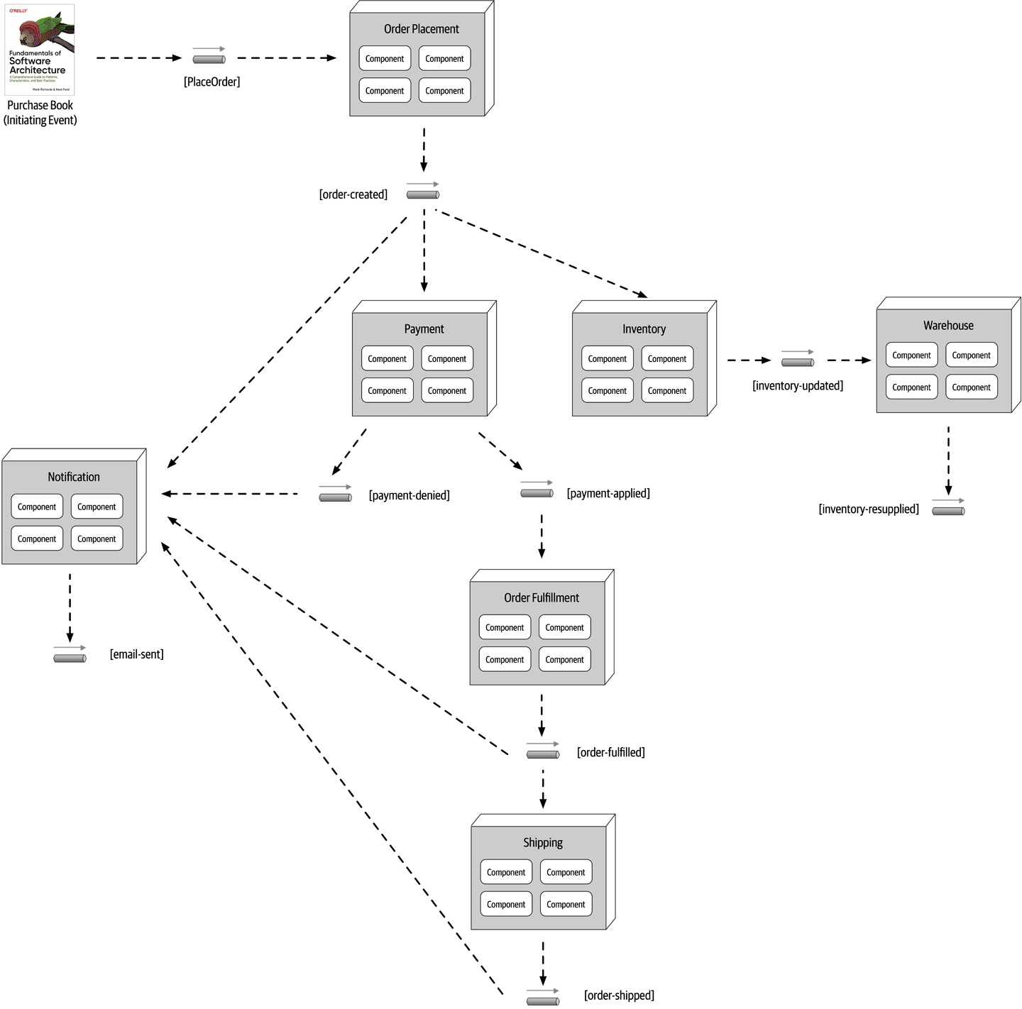
Figure 14-4. Example of the broker topology
The Notification event processor receives the order-created processing event and emails the customer. It then generates another processing event (email-sent). Notice that no other event processors are listening to that event. This is normal and illustrates the previous example describing architectural extensibility—an in-place hook so that other event processors can eventually tap into that event feed, if needed.
The Inventory event processor also listens for the order-created processing event and decrements the corresponding inventory for that book. It then advertises this action through an inventory-updated processing event, which is in turn picked up by the Warehouse event processor to manage the corresponding inventory between warehouses, reordering items if supplies get too low.
Payment event processor also receives the order-created processing event and charges the customer’s credit card for the order that was just created. Notice in Payment event processor: one to notify the rest of the system that the payment was applied (payment-applied) and one processing event to notify the rest of the system that the payment was denied (payment-denied). Notice that the Notification event processor is interested in the payment-denied processing event, because it must, in turn, send an email to the customer informing them that they must update their credit card information or choose a different payment method. The OrderFulfillment event processor listens to the payment-applied processing event and does order picking and packing. Once completed, it then advertises to the rest of the system that it fulfilled the order via an order-fulfilled processing event. Notice that both the Notification processing unit and the Shipping processing unit listen to this processing event. Concurrently, the Notification event notifies the customer that the order has been fulfilled and is ready for shipment, and at the same time the Shipping event processor selects a shipping method. The Shipping event processor ships the order and sends out an order-shipped processing event, which the Notification event processor also listens for to notify the customer of the order status change.
In analyzing the prior example, notice that all of the event processors are highly decoupled and independent of each other. The best way to understand the broker topology is to think about it as a relay race. In a relay race, runners hold a baton (a wooden stick) and run for a certain distance (say 1.5 kilometers), then hand off the baton to the next runner, and so on down the chain until the last runner crosses the finish line. In relay races, once a runner hands off the baton, that runner is done with the race and moves on to other things. This is also true with the broker topology. Once an event processor hands off the event, it is no longer involved with the processing of that specific event and is available to react to other initiating or processing events. In addition, each event processor can scale independently from one other to handle varying load conditions or backups in the processing within that event. The topics provide the back pressure point if an event processor comes down or slows down due to some environment issue.
While performance, responsiveness, and scalability are all great benefits of the broker topology, there are also some negatives about it.
PlaceOrder event).Payment event processor crashing and not completing its assigned task), no one in the system is aware of that crash. The business process gets stuck and is unable to move without some sort of automated or manual intervention. Furthermore, all other processes are moving along without regard for the error. For example, the Inventory event processor still decrements the inventory, and all other event processors react as though everything is fine.| Advantages | Disadvantages |
|---|---|
Highly decoupled event processors | Workflow control |
High scalability | Error handling |
High responsiveness | Recoverability |
High performance | Restart capabilities |
High fault tolerance | Data inconsistency |
Mediator Topology
The mediator topology of event-driven architecture addresses
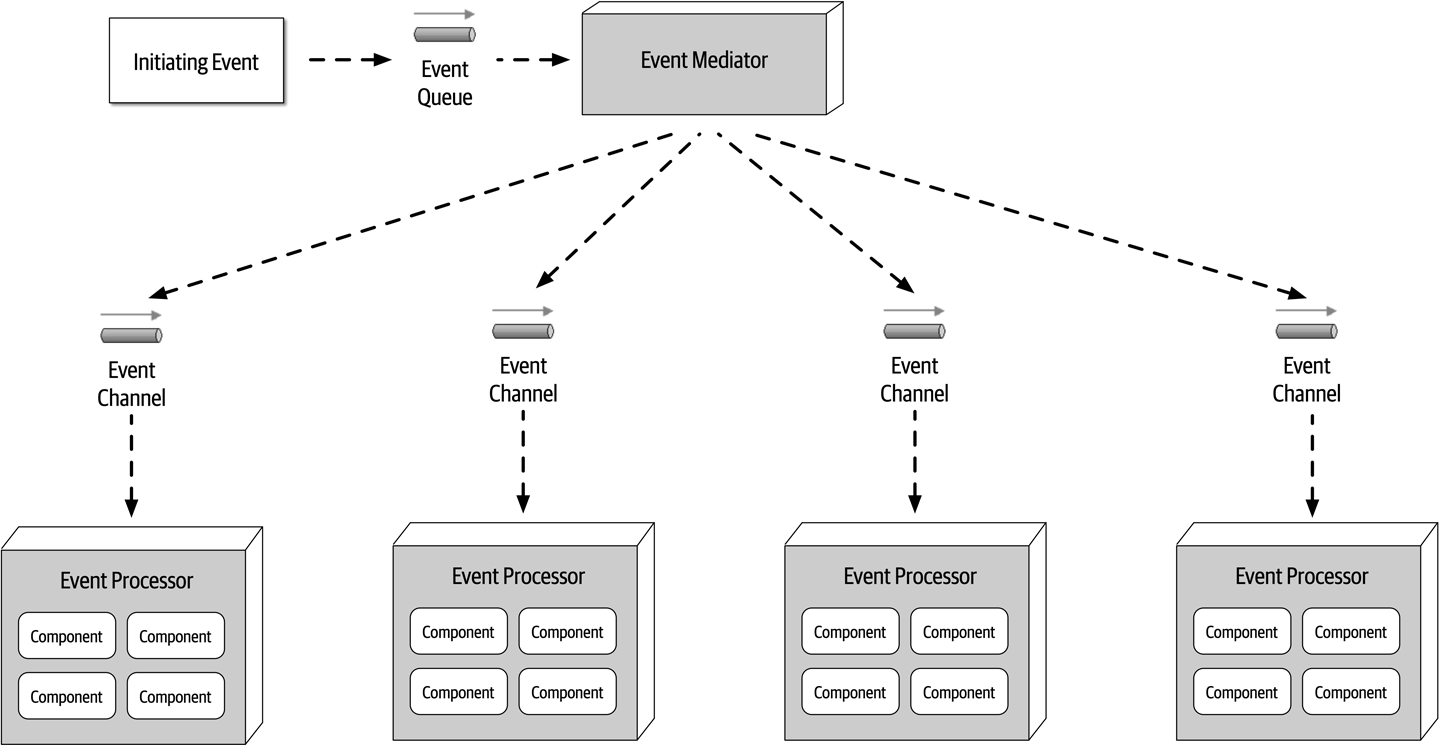
Figure 14-5. Mediator topology
In most implementations of the mediator topology, there are multiple mediators, usually associated with a particular domain or grouping of events. This reduces the single point of failure issue associated with this topology and also increases overall throughput and performance. For example, there might be a customer mediator that handles all customer-related events (such as new customer registration and profile update), and another mediator that handles order-related activities (such as adding an item to a shopping cart and checking out).
The event mediator can
BPEL is good for complex and dynamic workflows, but it does not work well for those event workflows requiring long-running transactions involving human intervention throughout the event process. For example, suppose a trade is being placed through a place-trade initiating event. The event mediator accepts this event, but during the processing finds that a manual approval is required because the trade is over a certain amount of shares. In this case the event mediator would have to stop the event processing, send a notification to a senior trader for the manual approval, and wait for that approval to occur. In these cases a Business Process Management (BPM) engine such as jBPM would be required.
It is important to know the types of events that will be processed through the mediator in order to make the correct choice for the implementation of the event mediator. Choosing Apache Camel for complex and long-running events involving human interaction would be extremely difficult to write and maintain. By the same token, using a BPM engine for simple event flows would take months of wasted effort when the same thing could be accomplished in Apache Camel in a matter of days.
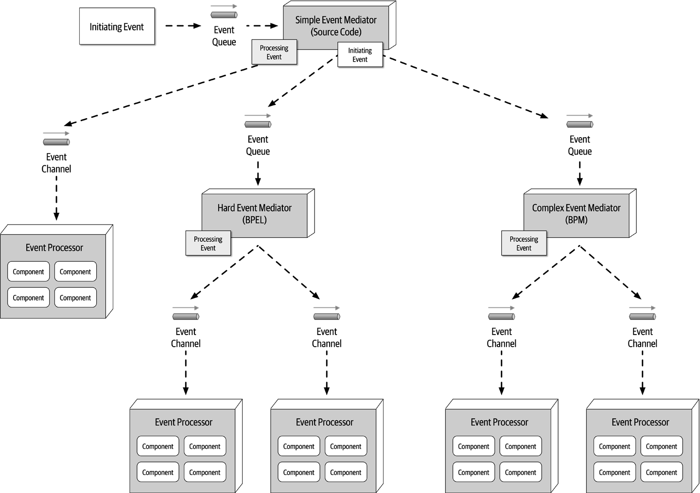
Figure 14-6. Delegating the event to the appropriate type of event mediator
Notice in Figure 14-6 that the Simple Event Mediator generates and sends a processing event when the event workflow is simple and can be handled by the simple mediator. However, notice that when the initiating event coming into the Simple Event Mediator is classified as either hard or complex, it forwards the original initiating event to the corresponding mediators (BPEL or BMP). The Simple Event Mediator, having intercepted the original event, may still be responsible for knowing when that event is complete, or it simply delegates the entire workflow (including client notification) to the other mediators.
To illustrate how the mediator topology works, consider the same retail order entry system example described in the prior broker topology section, but this time using the mediator topology. In this example, the mediator knows the steps required to process this particular event. This event flow (internal to the mediator component) is illustrated in Figure 14-7.
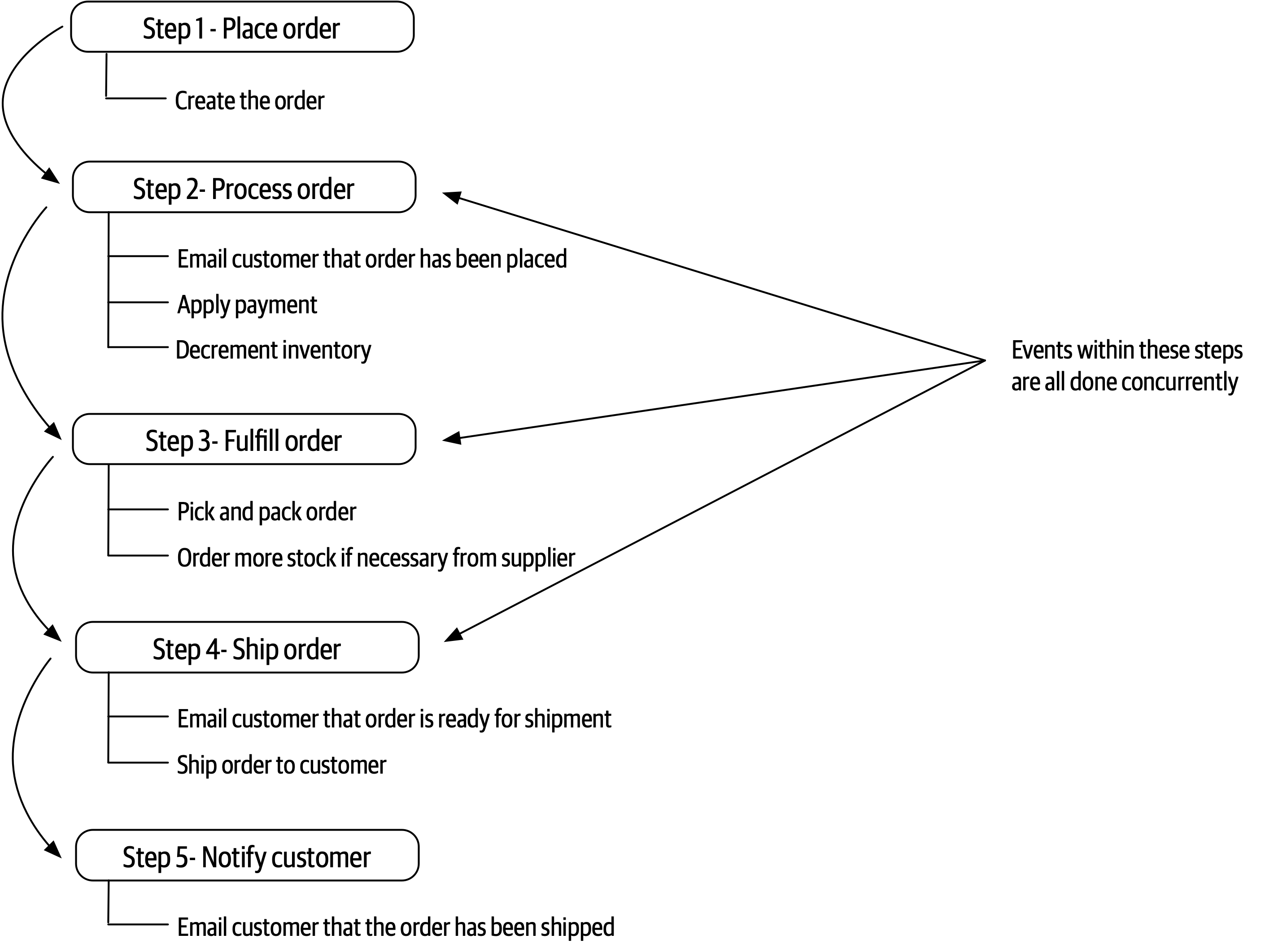
Figure 14-7. Mediator steps for placing an order
In keeping with the prior example, the same initiating event (PlaceOrder) is sent to the customer-event-queue for processing. The Customer mediator picks up this initiating event and begins generating processing events based on the flow in Figure 14-7. Notice that the multiple events shown in steps 2, 3, and 4 are all done concurrently and serially between steps. In other words, step 3 (fulfill order) must be completed and acknowledged before the customer can be notified that the order is ready to be shipped in step 4 (ship order).
Once the initiating event has been received, the Customer mediator generates a create-order processing event and sends this message to the order-placement-queue (see Figure 14-8). The OrderPlacement event processor accepts this event and validates and creates the order, returning to the mediator an acknowledgement along with the order ID. At this point the mediator might send that order ID back to the customer, indicating that the order was placed, or it might have to continue until all the steps are complete (this would be based on specific business rules about order placement).
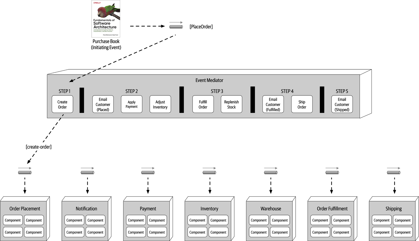
Figure 14-8. Step 1 of the mediator example
Now that step 1 is complete, the mediator now moves to step 2 (see Figure 14-9) and generates three messages at the same time: email-customer, apply-payment, and adjust-inventory. These processing events are all sent to their respective queues. All three event processors receive these messages, perform their respective tasks, and notify the mediator that the processing has been completed. Notice that the mediator must wait until it receives acknowledgement from all three parallel processes before moving on to step 3. At this point, if an error occurs in one of the parallel event processors, the mediator can take corrective action to fix the problem (this is discussed later in this section in more detail).
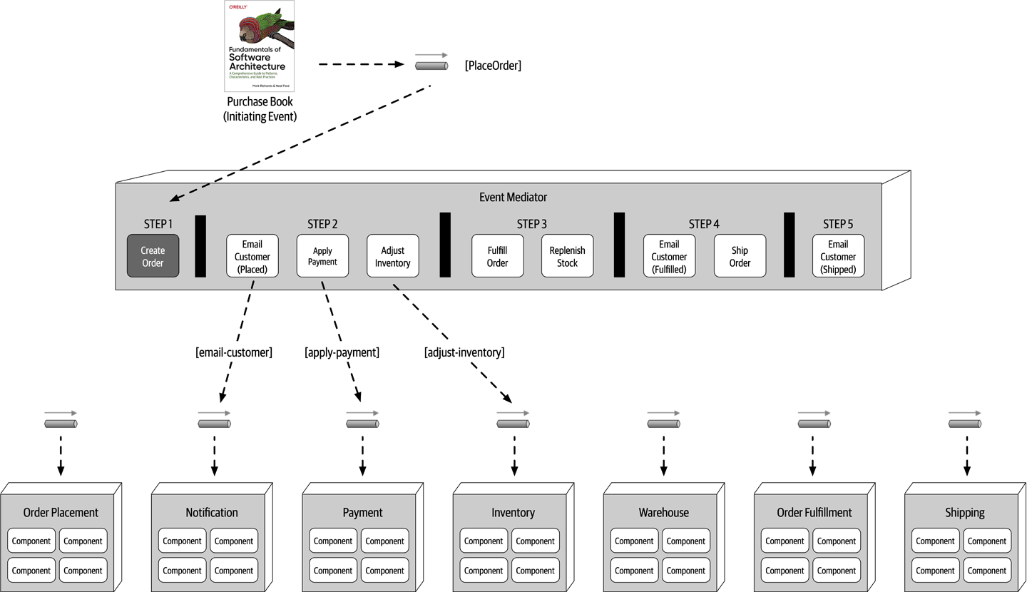
Figure 14-9. Step 2 of the mediator example
Once the mediator gets a successful acknowledgment from all of the event processors in step 2, it can move on to step 3 to fulfill the order (see Figure 14-10). Notice once again that both of these events (fulfill-order and order-stock) can occur simultaneously. The OrderFulfillment and Warehouse event processors accept these events, perform their work, and return an acknowledgement to the mediator.
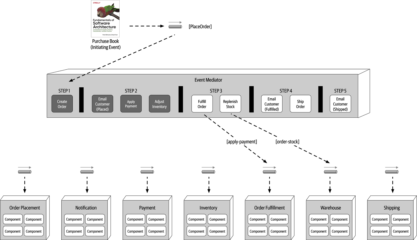
Figure 14-10. Step 3 of the mediator example
Once these events are complete, the mediator then moves on to step 4 (see Figure 14-11) to ship the order. This step generates another email-customer processing event with specific information about what to do (in this case, notify the customer that the order is ready to be shipped), as well as a ship-order event.
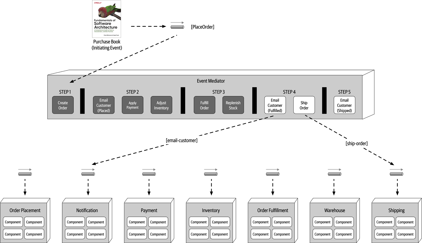
Figure 14-11. Step 4 of the mediator example
Finally, the mediator moves to step 5 (see Figure 14-12) and generates another contextual email_customer event to notify the customer that the order has been shipped. At this point the workflow is done, and the mediator marks the initiating event flow complete and removes all state associated with the initiating event.
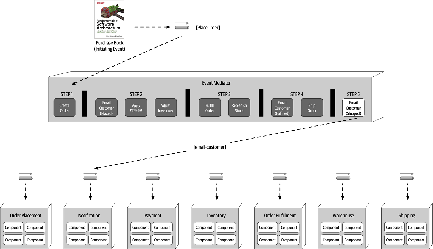
Figure 14-12. Step 5 of the mediator example
The mediator component has knowledge and control over the workflow, something the broker topology does not have. Because the mediator controls the workflow, it can maintain event state and manage error handling, recoverability, and restart capabilities. For example, suppose in the prior example the payment was not applied due to the credit card being expired. In this case the mediator receives this error condition, and knowing the order cannot be fulfilled (step 3) until payment is applied, stops the workflow and records the state of the request in its own persistent datastore. Once payment is eventually applied, the workflow can be restarted from where it left off (in this case, the beginning of step 3).
Another inherent difference between the broker and mediator topology is how the processing events differ in terms of their meaning and how they are used. In the broker topology example in the previous section, the processing events were published as events that had occurred in the system (such as order-created, payment-applied, and email-sent). The event processors took some action, and other event processors react to that action. However, in the mediator topology, processing events such as place-order, send-email, and fulfill-order are commands (things that need to happen) as opposed to events (things that have already happened).
| Advantages | Disadvantages |
|---|---|
Workflow control | More coupling of event processors |
Error handling | Lower scalability |
Recoverability | Lower performance |
Restart capabilities | Lower fault tolerance |
Better data consistency | Modeling complex workflows |
The choice between the broker and mediator topology essentially comes down to a trade-off between workflow control and error handling capability versus high performance and scalability. Although performance and scalability are still good within the mediator topology, they are not as high as with the broker topology.
Asynchronous Capabilities
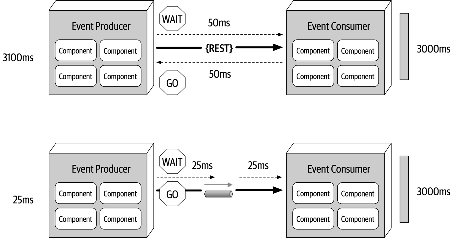
Figure 14-13. Synchronous versus asynchronous communication
This is a good example of the difference between responsiveness and performance. When the user does not need any information back (other than an acknowledgement or a thank you message), why make the user wait? Responsiveness is all about notifying the user that the action has been accepted and will be processed momentarily, whereas performance is about making the end-to-end process faster. Notice that nothing was done to optimize the way the comment service processes the text—in both cases it is still taking 3,000 milliseconds. Addressing performance would have been optimizing the comment service to run all of the text and grammar parsing engines in parallel with the use of caching and other similar techniques. The bottom example in Figure 14-13 addresses the overall responsiveness of the system but not the performance of the system.
The difference in response time between the two examples in Figure 14-13 from 3,100 milliseconds to 25 milliseconds is staggering. There is one caveat. On the synchronous path shown on the top of the diagram, the end user is guaranteed that the comment has been posted. However, on the bottom path there is only the acknowledgement of the post, with a future promise that eventually the comment will get posted. From the end user’s perspective, the comment has been posted. But what happens if the user had typed a bad word in the comment? In this case the comment would be rejected, but there is no way to get back to the end user. Or is there? In this example, assuming the user is registered with the website (which to post a comment they would have to be), a message could be sent to the user indicating a problem with the comment and some suggestions on how to repair it. This is a simple example. What about a more complicated example where the purchase of some stock is taking place asynchronously (called a stock trade) and there is no way to get back to the user?
The main issue with asynchronous communications is error handling. While responsiveness is significantly improved, it is difficult to address error conditions, adding to the complexity of the event-driven system. The next section addresses this issue with a pattern of reactive architecture called the workflow event pattern.
Error Handling
Once the workflow processor receives an error, it tries to figure out what is wrong with the message. This could be a static, deterministic error, or it could leverage some machine learning algorithms to analyze the message to see some anomaly in the data. Either way, the workflow processor programmatically (without human intervention) makes changes to the original data to try and repair it, and then sends it back to the originating queue. The event consumer sees this message as a new one and tries to process it again, hopefully this time with some success. Of course, there are many times when the workflow processor cannot determine what is wrong with the message. In these cases the workflow processor sends the message off to another queue, which is then received in what is usually called a “dashboard,” an application that looks similar to the Microsoft’s Outlook or Apple’s Mail. This dashboard usually resides on the desktop of a person of importance, who then looks at the message, applies manual fixes to it, and then resubmits it to the original queue (usually through a reply-to message header variable).
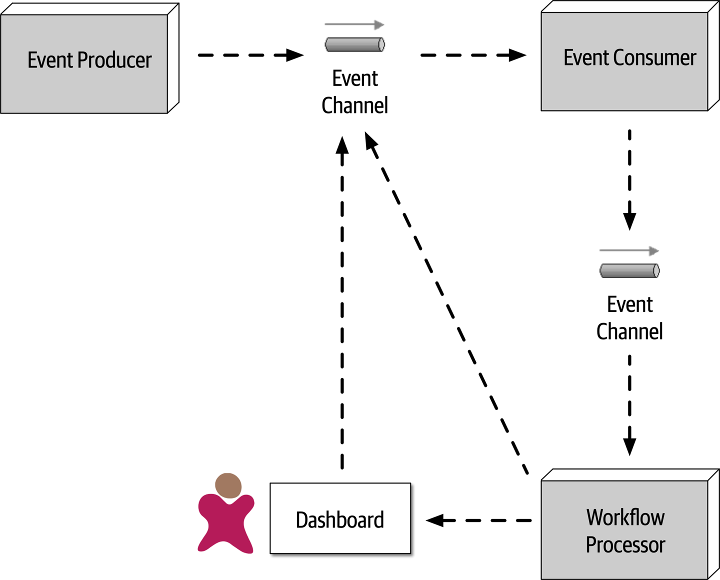
Figure 14-14. Workflow event pattern of reactive architecture
To illustrate the workflow event pattern, suppose a trading advisor in one part of the country accepts trade orders (instructions on what stock to buy and for how many shares) on behalf of a large trading firm in another part of the country. The advisor batches up the trade orders (what is usually called a basket) and asynchronously sends those to the large trading firm to be placed with a broker so the stock can be purchased. To simplify the example, suppose the contract for the trade instructions must adhere to the following:
ACCOUNT(String),SIDE(String),SYMBOL(String),SHARES(Long)
Suppose the large trading firm receives the following basket of Apple (AAPL) trade orders from the trading advisor:
12654A87FR4,BUY,AAPL,1254 87R54E3068U,BUY,AAPL,3122 6R4NB7609JJ,BUY,AAPL,5433 2WE35HF6DHF,BUY,AAPL,8756 SHARES 764980974R2,BUY,AAPL,1211 1533G658HD8,BUY,AAPL,2654
Notice the forth trade instruction (2WE35HF6DHF,BUY,AAPL,8756 SHARES) has the word SHARES after the number of shares for the trade. When these asynchronous trade orders are processed by the large trading firm without any error handling capabilities, the following error occurs within the trade placement service:
Exception in thread "main" java.lang.NumberFormatException: For input string: "8756 SHARES" at java.lang.NumberFormatException.forInputString (NumberFormatException.java:65) at java.lang.Long.parseLong(Long.java:589) at java.lang.Long.<init>(Long.java:965) at trading.TradePlacement.execute(TradePlacement.java:23) at trading.TradePlacement.main(TradePlacement.java:29)
When this exception occurs, there is nothing that the trade placement service can do, because this was an asynchronous request, except to possibly log the error condition. In other words, there is no user to synchronously respond to and fix the error.
2WE35HF6DHF,BUY,AAPL,8756 SHARES), the Trade Placement service immediately delegates the error via asynchronous messaging to the Trade Placement Error service for error handling, passing with the error information about the exception: Trade Placed: 12654A87FR4,BUY,AAPL,1254 Trade Placed: 87R54E3068U,BUY,AAPL,3122 Trade Placed: 6R4NB7609JJ,BUY,AAPL,5433 Error Placing Trade: "2WE35HF6DHF,BUY,AAPL,8756 SHARES" Sending to trade error processor <-- delegate the error fixing and move on Trade Placed: 764980974R2,BUY,AAPL,1211 ...
The Trade Placement Error service (acting as the workflow delegate) receives the error and inspects the exception. Seeing that it is an issue with the word SHARES in the number of shares field, the Trade Placement Error service strips off the word SHARES and resubmits the trade for reprocessing:
Received Trade Order Error: 2WE35HF6DHF,BUY,AAPL,8756 SHARES Trade fixed: 2WE35HF6DHF,BUY,AAPL,8756 Resubmitting Trade For Re-Processing
The fixed trade is then processed successfully by the trade placement service:
... trade placed: 1533G658HD8,BUY,AAPL,2654 trade placed: 2WE35HF6DHF,BUY,AAPL,8756 <-- this was the original trade in error
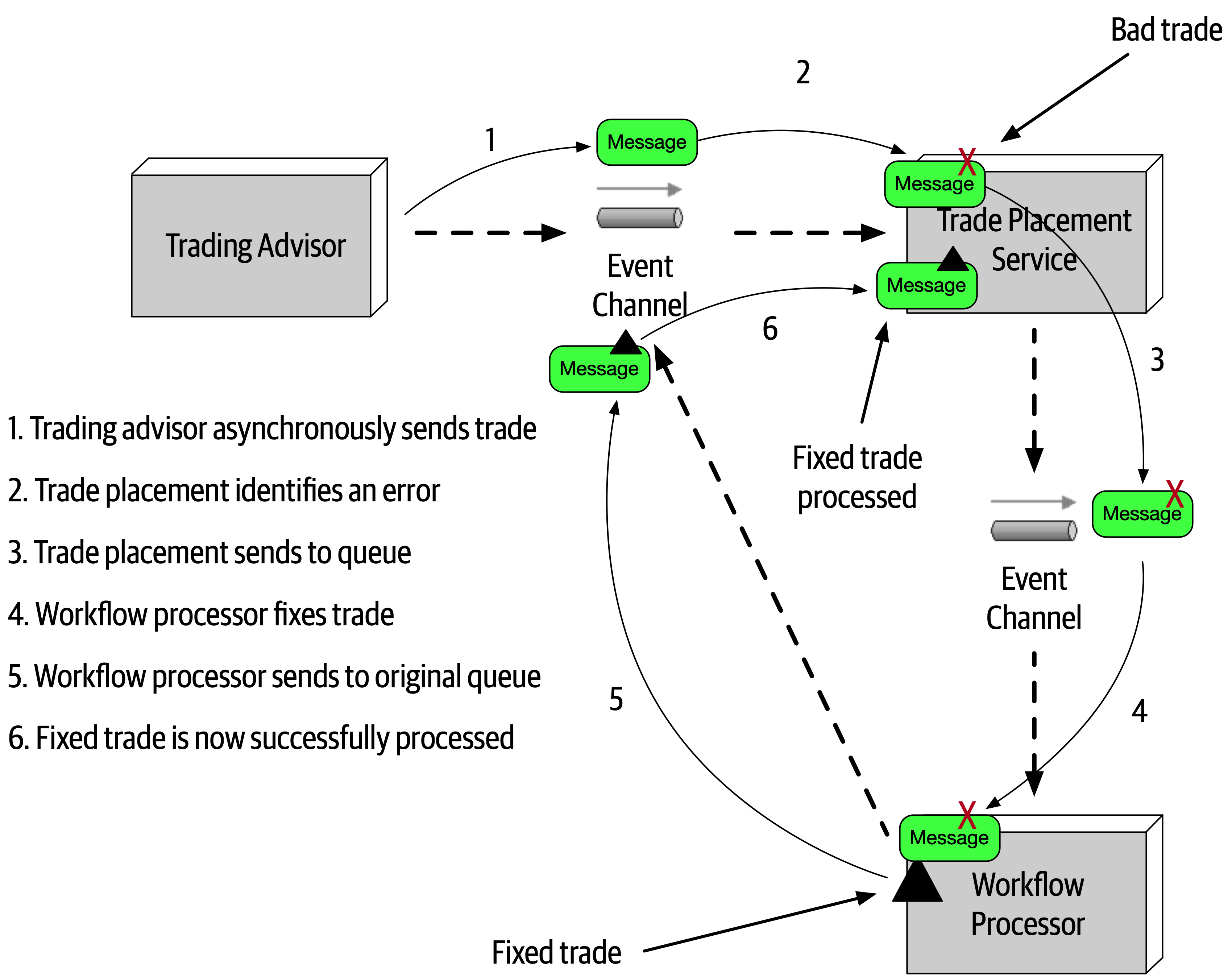
Figure 14-15. Error handling with the workflow event pattern
One of the consequences of the workflow event pattern is that messages in error are processed out of sequence when they are resubmitted. In our trading example, the order of messages matters, because all trades within a given account must be processed in order (for example, a SELL for IBM must occur before a BUY for AAPL within the same brokerage account). Although not impossible, it is a complex task to maintain message order within a given context (in this case the brokerage account number). One way this can be addressed is by the Trade Placement service queueing and storing the account number of the trade in error. Any trade with that same account number would be stored in a temporary queue for later processing (in FIFO order). Once the trade originally in error is fixed and processed, the Trade Placement service then de-queues the remaining trades for that same account and processes them in order.
Preventing Data Loss
Event Processor A asynchronously sends a message to a queue. Event Processor B accepts the message and inserts the data within the message into a database. As illustrated in -
The message never makes it to the queue from
EventProcessorA; or even if it does, the broker goes down before the next event processor can retrieve the message. -
EventProcessorBde-queues the next available message and crashes before it can process the event. -
EventProcessorBis unable to persist the message to the database due to some data error.
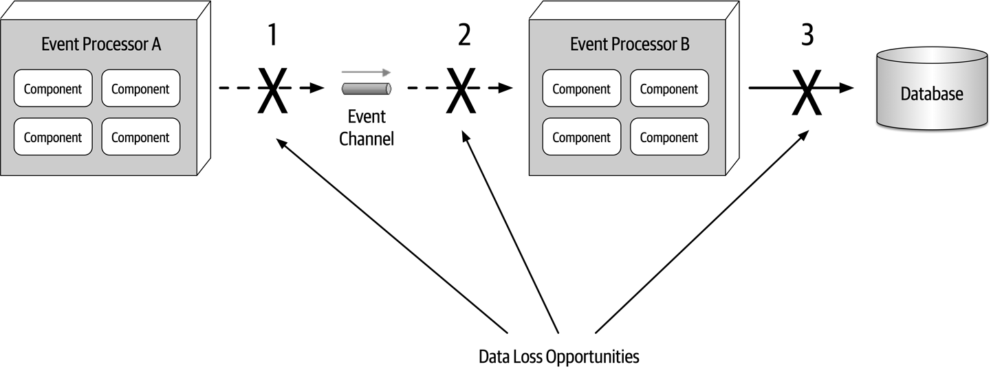
Figure 14-16. Where data loss can happen within an event-driven architecture
Each of these areas of data loss can be mitigated through basic messaging techniques. Issue 1 (the message never makes it to the queue) is easily solved by leveraging persisted message queues, along with something called synchronous send.
Event Processor B de-queues the next available message and crashes before it can process the event) can also be solved using a basic technique of messaging called client acknowledge mode. Event Processor B crashes, the message is still preserved in the queue, preventing message loss in this part of the message flow.Event Processor B is unable to persist the message to the database due to some data error) is addressed through leveraging ACID (atomicity, consistency, isolation, durability) transactions via a database commit. Once the database commit happens, the data is guaranteed to be persisted in the database. Event Processor A all the way to the database. These techniques are illustrated in 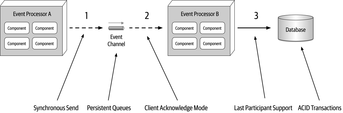
Figure 14-17. Preventing data loss within an event-driven architecture
Broadcast Capabilities
One of the other unique characteristics of event-driven architecture is the capability
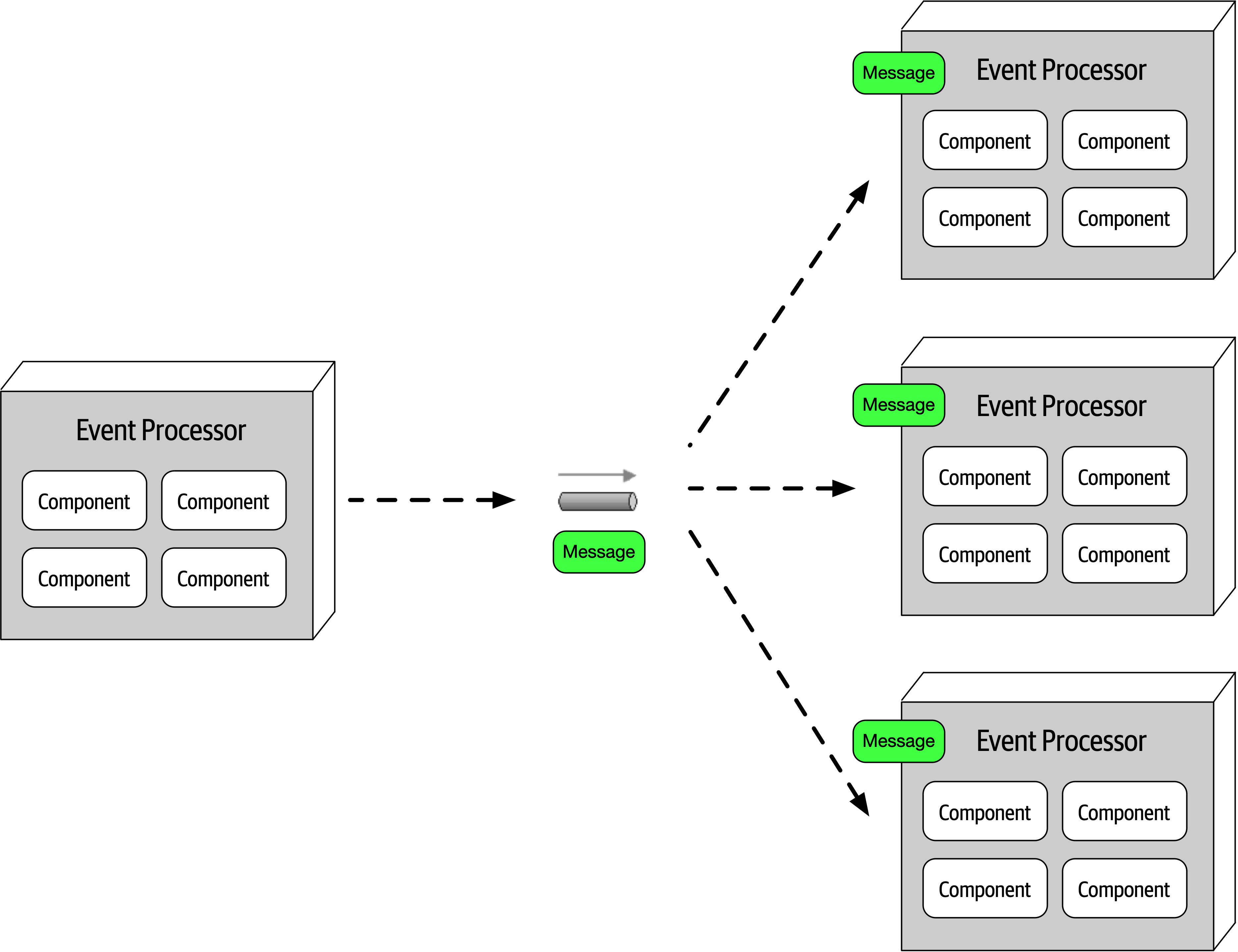
Figure 14-18. Broadcasting events to other event processors
Broadcasting is perhaps the highest level of decoupling between event processors because the producer of the broadcast message usually does not know which event processors will be receiving the broadcast message and more importantly, what they will do with the message. Broadcast capabilities are an essential part of patterns for eventual consistency, complex event processing (CEP), and a host of other situations. Consider frequent changes in stock prices for instruments traded on the stock market. Every ticker (the current price of a particular stock) might influence a number of things. However, the service publishing the latest price simply broadcasts it with no knowledge of how that information will be used.
Request-Reply
So far in this chapter we’ve dealt with asynchronous requests that don’t need an immediate response from the event consumer.
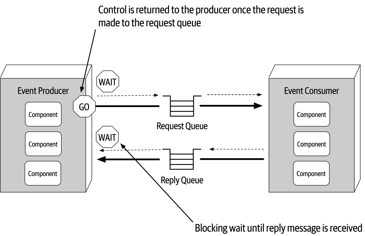
Figure 14-19. Request-reply message processing
There are two primary techniques for implementing request-reply messaging. The first (and most common) technique is to use a correlation ID contained in the message header.
-
The event producer sends a message to the request queue and records the unique message ID (in this case ID 124). Notice that the correlation ID (CID) in this case is
null. -
The event producer now does a blocking wait on the reply queue with a message filter (also called a message selector), where the correlation ID in the message header equals the original message ID (in this case 124). Notice there are two messages in the reply queue: message ID 855 with correlation ID 120, and message ID 856 with correlation ID 122. Neither of these messages will be picked up because the correlation ID does not match what the event consumer is looking for (CID 124).
-
The event consumer receives the message (ID 124) and processes the request.
-
The event consumer creates the reply message containing the response and sets the correlation ID (CID) in the message header to the original message ID (124).
-
The event consumer sends the new message (ID 857) to the reply queue.
-
The event producer receives the message because the correlation ID (124) matches the message selector from step 2.
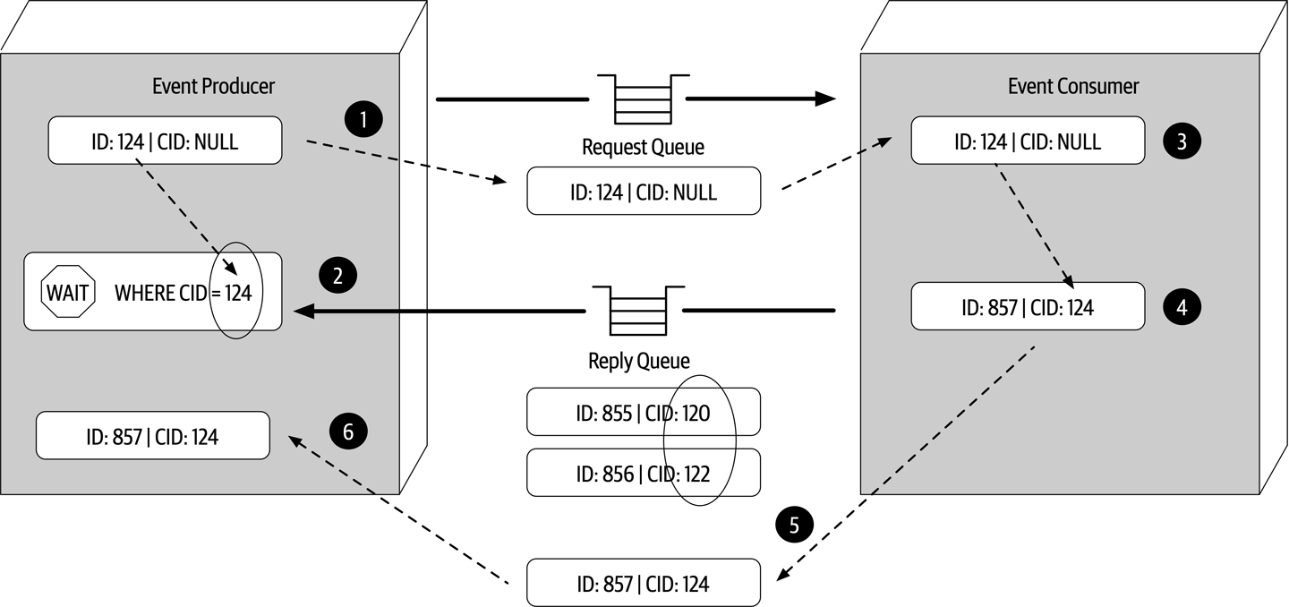
Figure 14-20. Request-reply message processing using a correlation ID
The other technique used to implement request-reply messaging is to use a temporary queue for the reply queue.
-
The event producer creates a temporary queue (or one is automatically created, depending on the message broker) and sends a message to the request queue, passing the name of the temporary queue in the reply-to header (or some other agreed-upon custom attribute in the message header).
-
The event producer does a blocking wait on the temporary reply queue. No message selector is needed because any message sent to this queue belongs solely to the event producer that originally sent to the message.
-
The event consumer receives the message, processes the request, and sends a response message to the reply queue named in the reply-to header.
-
The event processor receives the message and deletes the temporary queue.
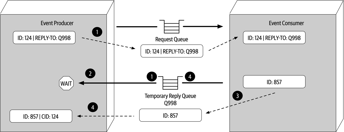
Figure 14-21. Request-reply message processing using a temporary queue
While the temporary queue technique is much simpler, the message broker must create a temporary queue for each request made and then delete it immediately afterward. Large messaging volumes can significantly slow down the message broker and impact overall performance and responsiveness. For this reason we usually recommend using the correlation ID technique.
Choosing Between Request-Based and Event-Based
The request-based model and event-based model are both viable approaches for designing software systems.
| Advantages over request-based | Trade-offs |
|---|---|
Better response to dynamic user content | Only supports eventual consistency |
Better scalability and elasticity | Less control over processing flow |
Better agility and change management | Less certainty over outcome of event flow |
Better adaptability and extensibility | Difficult to test and debug |
Better responsiveness and performance | |
Better real-time decision making | |
Better reaction to situational awareness |
Hybrid Event-Driven Architectures
While many applications leverage the event-driven architecture style as the primary overarching architecture, in many cases event-driven architecture is used in conjunction with other architecture styles, forming what is known as a hybrid architecture. Some common architecture styles that leverage event-driven architecture as part of another architecture style include microservices and space-based architecture. Other hybrids that are possible include an event-driven microkernel architecture and an event-driven pipeline architecture.
Adding event-driven architecture to any architecture style helps remove bottlenecks, provides a back pressure point in the event requests get backed up, and provides a level of user responsiveness not found in other architecture styles. Both microservices and space-based architecture leverage messaging for data pumps, asynchronously sending data to another processor that in turn updates data in a database. Both also leverage event-driven architecture to provide a level of programmatic scalability to services in a microservices architecture and processing units in a space-based architecture when using messaging for interservice communication.
Architecture Characteristics Ratings
A one-star rating in the characteristics ratings table in Figure 14-22 means the specific
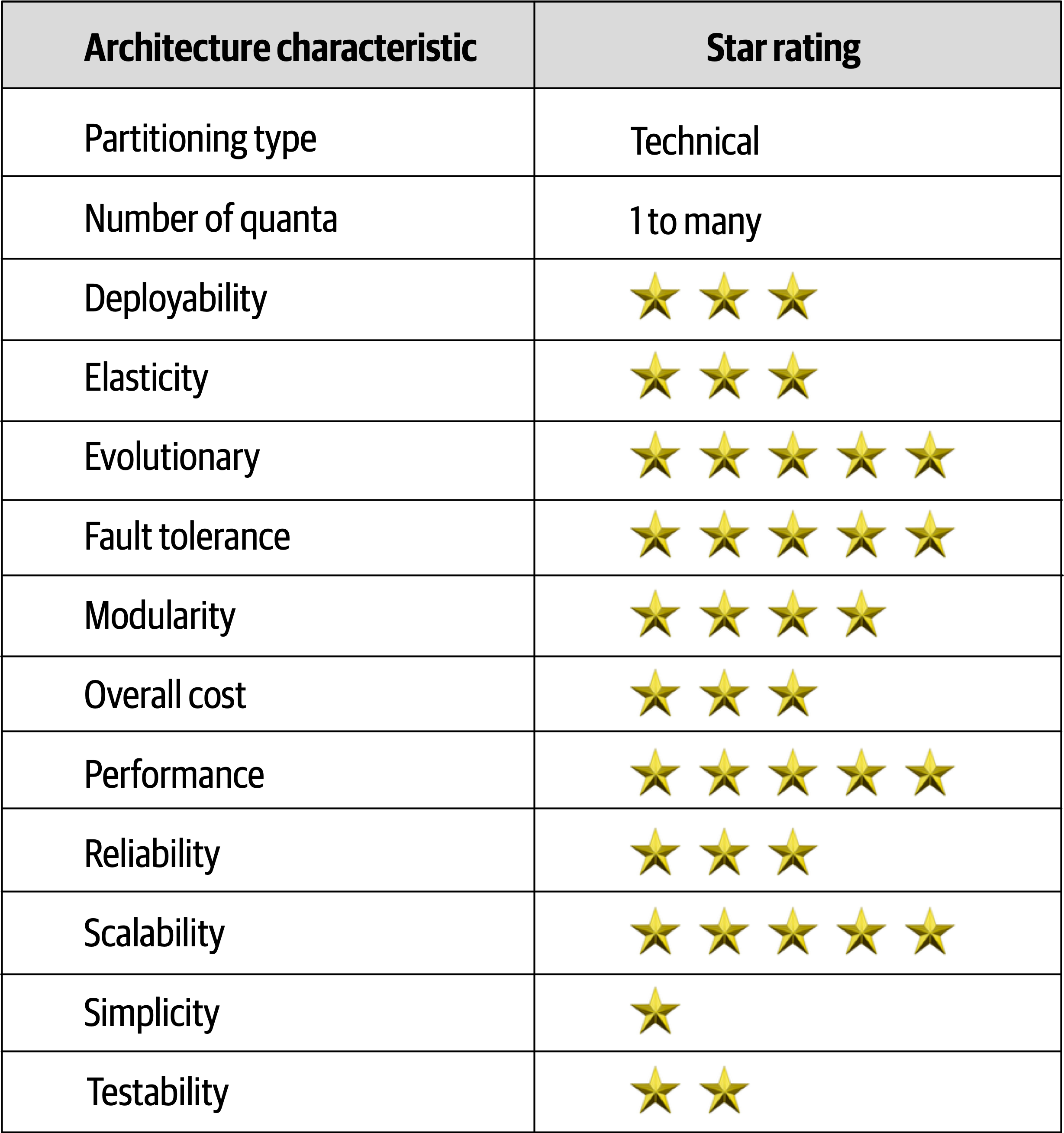
Figure 14-22. Event-driven architecture characteristics ratings
Event-driven architecture is primarily a technically
To illustrate this point, consider the example where one event processor sends a request to another event processor to place an order. The first event processor must wait for an order ID from the other event processor to continue. If the second event processor that places the order and generates an order ID is down, the first event processor cannot continue. Therefore, they are part of the same architecture quantum and share the same architectural characteristics, even though they are both sending and receiving asynchronous messages.
Chapter 15. Space-Based Architecture Style
Most web-based business applications follow the same general request flow: a request from a browser hits the web server, then an application server, then finally the database server.
In any high-volume application with a large concurrent user load, the database will usually be the final limiting factor in how many transactions you can process concurrently.
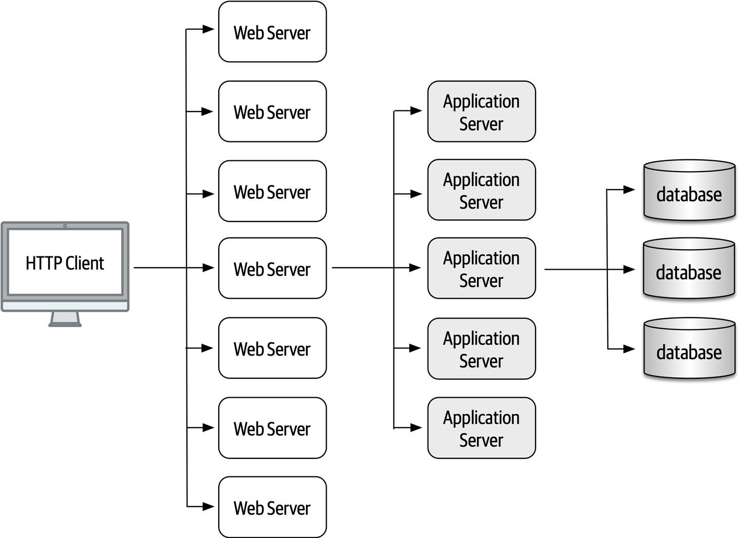
Figure 15-1. Scalability limits within a traditional web-based topology
General Topology
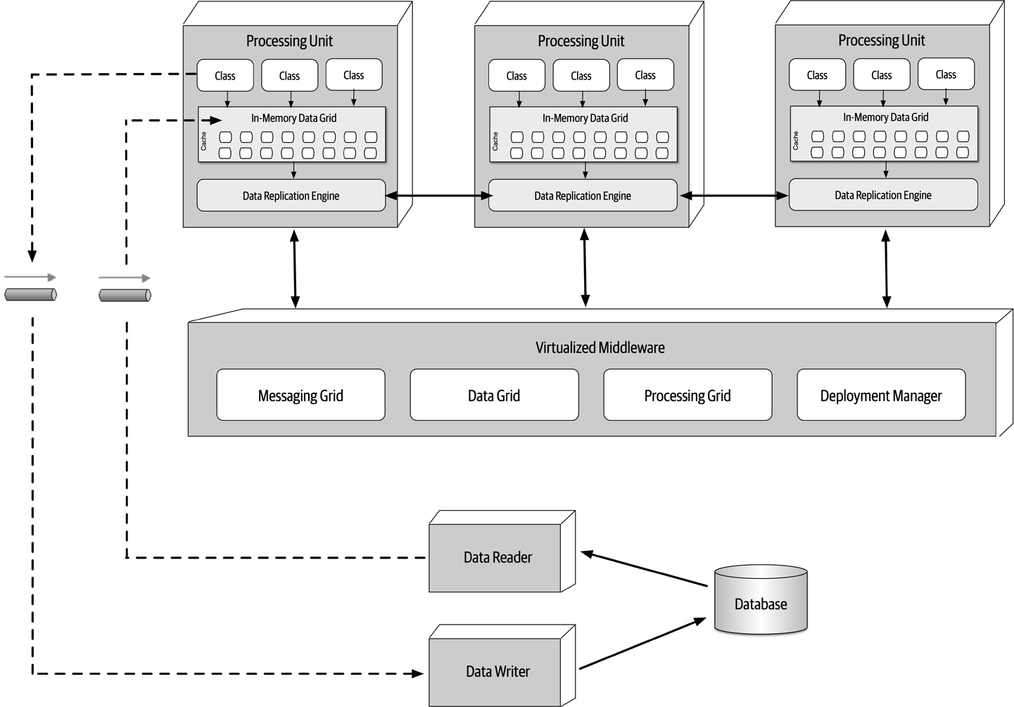
Figure 15-2. Space-based architecture basic topology
Processing Unit
The processing unit (illustrated in Figure 15-3) contains the application logic (or portions of the application logic).
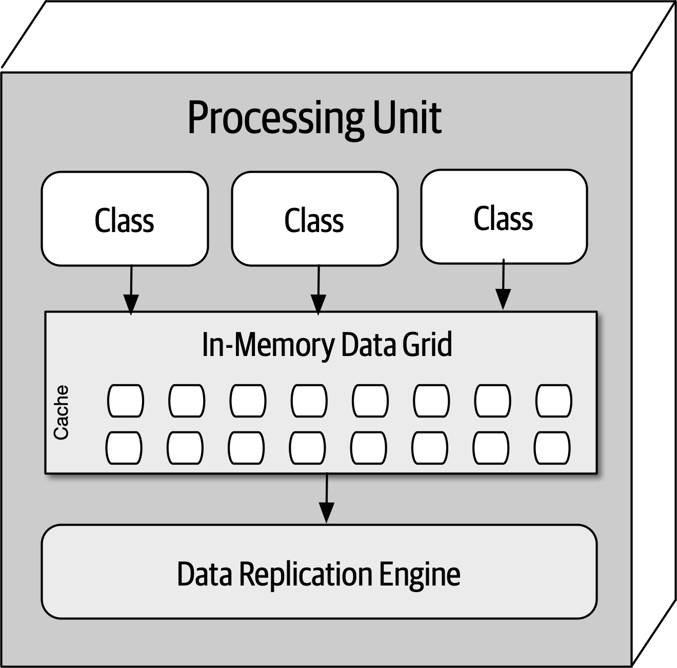
Figure 15-3. Processing unit
Virtualized Middleware
The virtualized middleware handles the infrastructure concerns within the architecture that control various
Messaging grid
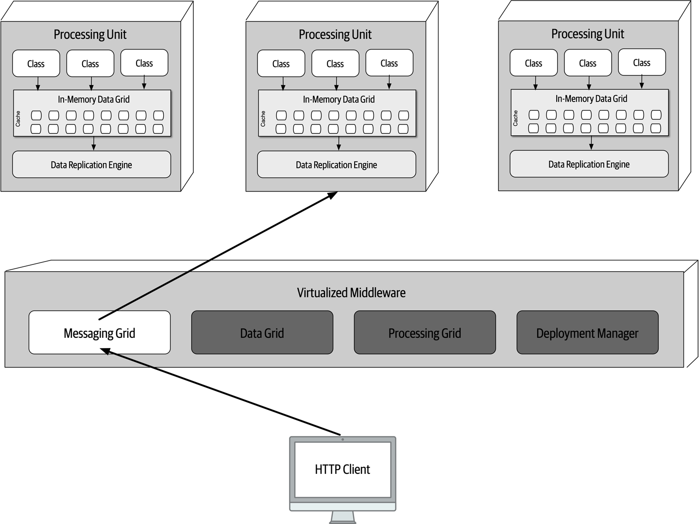
Figure 15-4. Messaging grid
Data grid
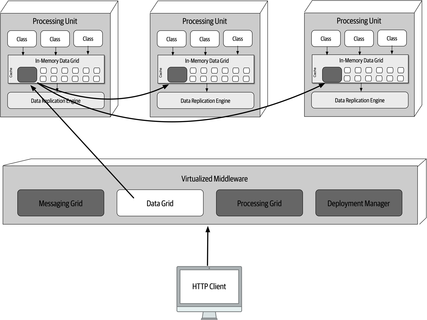
Figure 15-5. Data grid
Data is synchronized between processing units that contain the same named data grid. To illustrate this point, consider the following code in Java using Hazelcast that creates an internal
HazelcastInstancehz=Hazelcast.newHazelcastInstance();Map<String,CustomerProfile>profileCache=hz.getReplicatedMap("CustomerProfile");
CustomerProfile named cache from any of the processing units would have that change replicated to all other processing units containing that same named cache. Instance 1: Members {size:1, ver:1} [ Member [172.19.248.89]:5701 - 04a6f863-dfce-41e5-9d51-9f4e356ef268 this ] When another processing unit starts up with the same named cache, the member list of both services is updated to reflect the IP address and port of each processing unit:
Instance 1: Members {size:2, ver:2} [ Member [172.19.248.89]:5701 - 04a6f863-dfce-41e5-9d51-9f4e356ef268 this Member [172.19.248.90]:5702 - ea9e4dd5-5cb3-4b27-8fe8-db5cc62c7316 ] Instance 2: Members {size:2, ver:2} [ Member [172.19.248.89]:5701 - 04a6f863-dfce-41e5-9d51-9f4e356ef268 Member [172.19.248.90]:5702 - ea9e4dd5-5cb3-4b27-8fe8-db5cc62c7316 this ] When a third processing unit starts up, the member list of instance 1 and instance 2 are both updated to reflect the new third instance:
Instance 1: Members {size:3, ver:3} [ Member [172.19.248.89]:5701 - 04a6f863-dfce-41e5-9d51-9f4e356ef268 this Member [172.19.248.90]:5702 - ea9e4dd5-5cb3-4b27-8fe8-db5cc62c7316 Member [172.19.248.91]:5703 - 1623eadf-9cfb-4b83-9983-d80520cef753 ] Instance 2: Members {size:3, ver:3} [ Member [172.19.248.89]:5701 - 04a6f863-dfce-41e5-9d51-9f4e356ef268 Member [172.19.248.90]:5702 - ea9e4dd5-5cb3-4b27-8fe8-db5cc62c7316 this Member [172.19.248.91]:5703 - 1623eadf-9cfb-4b83-9983-d80520cef753 ] Instance 3: Members {size:3, ver:3} [ Member [172.19.248.89]:5701 - 04a6f863-dfce-41e5-9d51-9f4e356ef268 Member [172.19.248.90]:5702 - ea9e4dd5-5cb3-4b27-8fe8-db5cc62c7316 Member [172.19.248.91]:5703 - 1623eadf-9cfb-4b83-9983-d80520cef753 this ] Notice that all three instances know about each other (including themselves). Suppose instance 1 receives a request to update the customer profile information. When instance 1 updates the cache with a cache.put() or similar cache update method, the data grid (such as Hazelcast) will asynchronously update the other replicated caches with the same update, ensuring all three customer profile caches always remain in sync with one another.
Instance 1: Members {size:2, ver:4} [ Member [172.19.248.89]:5701 - 04a6f863-dfce-41e5-9d51-9f4e356ef268 this Member [172.19.248.91]:5703 - 1623eadf-9cfb-4b83-9983-d80520cef753 ] Instance 3: Members {size:2, ver:4} [ Member [172.19.248.89]:5701 - 04a6f863-dfce-41e5-9d51-9f4e356ef268 Member [172.19.248.91]:5703 - 1623eadf-9cfb-4b83-9983-d80520cef753 this ] Processing grid
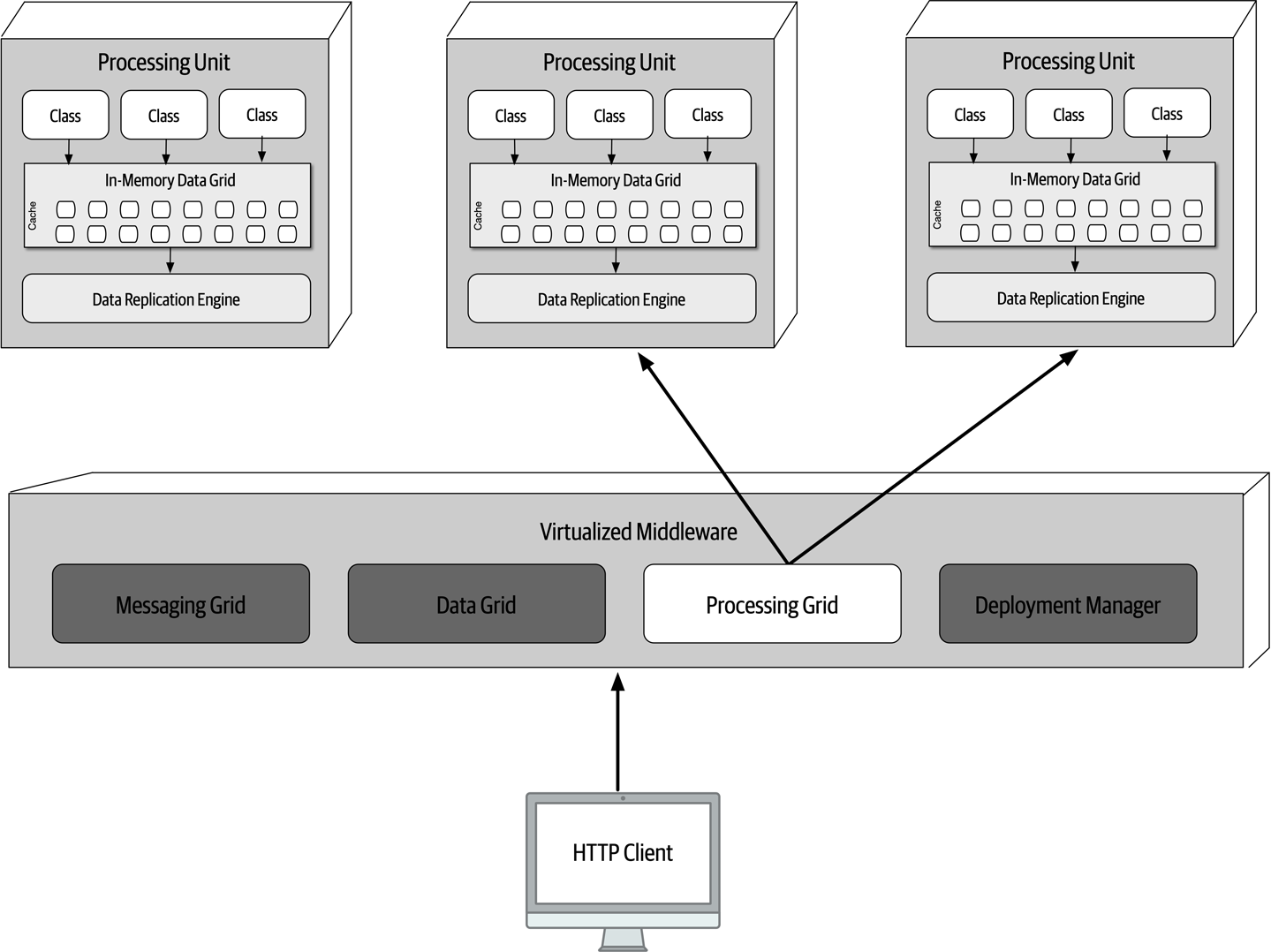
Figure 15-6. Processing grid
Deployment manager
Data Pumps
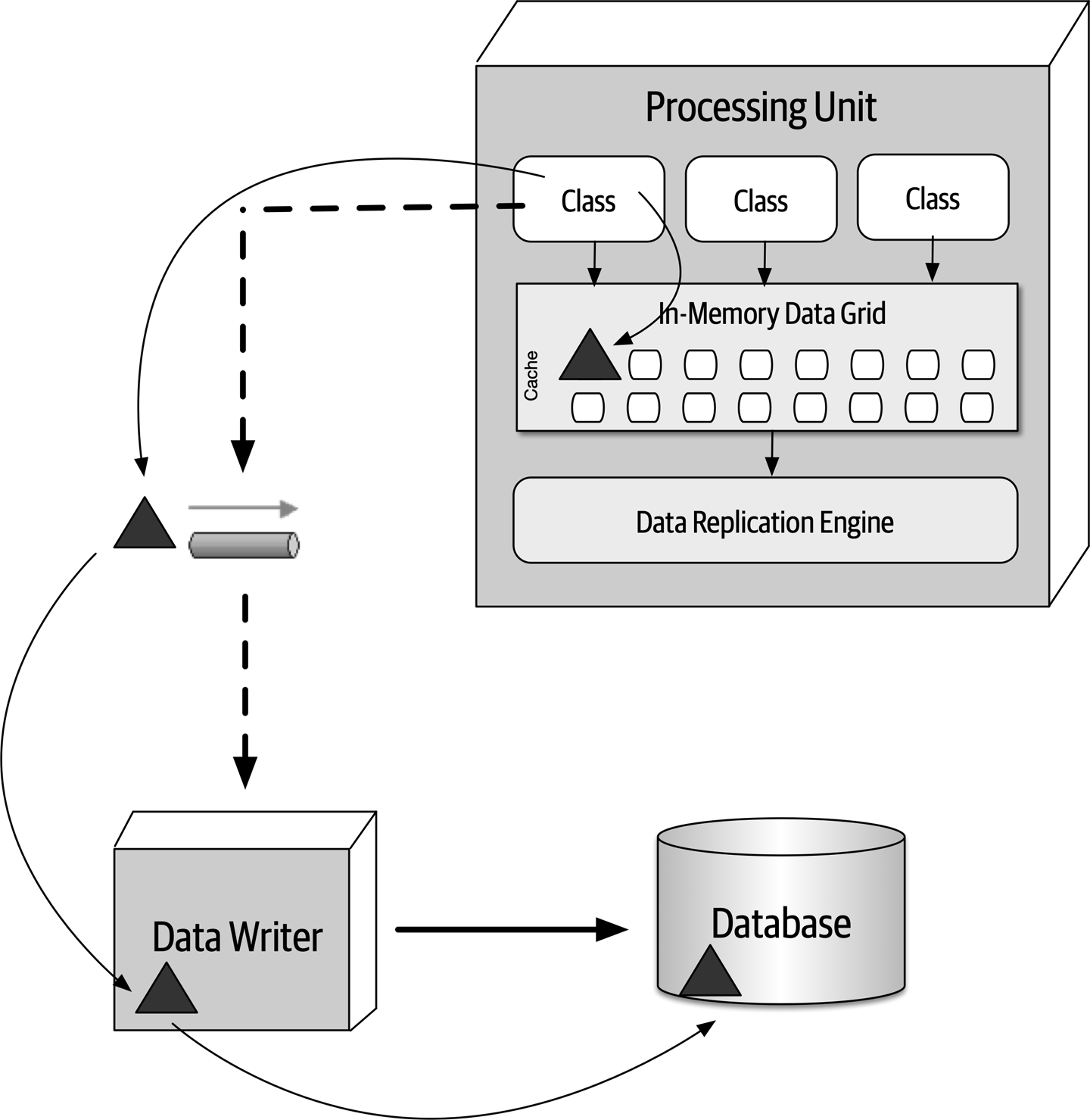
Figure 15-7. Data pump used to send data to a database
CustomerProfile, CustomerWishlist, and so on), or they can be dedicated to a processing unit domain (such as Customer) containing a much larger and general cache.Data Writers
A domain-based data writer contains all of the necessary database logic to handle all the updates within a particular domain (such as customer), regardless of the number of data pumps it is accepting.
Profile, WishList, Wallet, and Preferences) but only one data writer. The single customer data writer listens to all four data pumps and contains the necessary database logic (such as SQL) to update the customer-related data in the database. 
Figure 15-8. Domain-based data writer
Alternatively, each class of processing unit can have its own dedicated data writer component, as illustrated in Figure 15-9. In this model the data writer is dedicated to each corresponding data pump and contains only the database processing logic for that particular processing unit (such as Wallet). While this model tends to produce too many data writer components, it does provide better scalability and agility due to the alignment of processing unit, data pump, and data writer.
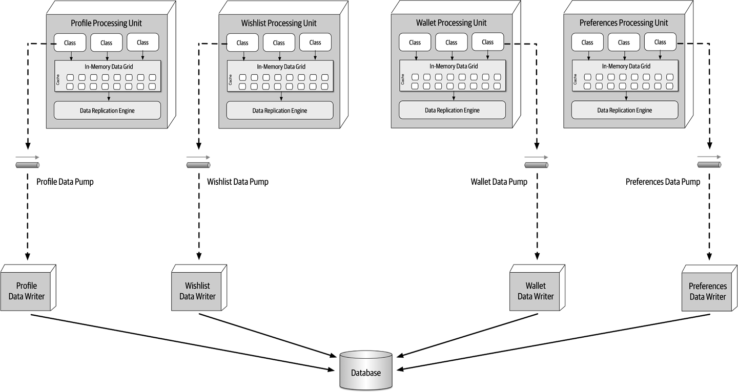
Figure 15-9. Dedicated data writers for each data pump
Data Readers
Whereas data writers take on the responsibility for updating the database, data readers take on the responsibility for reading data from the database and sending it to the processing units via a reverse data pump.
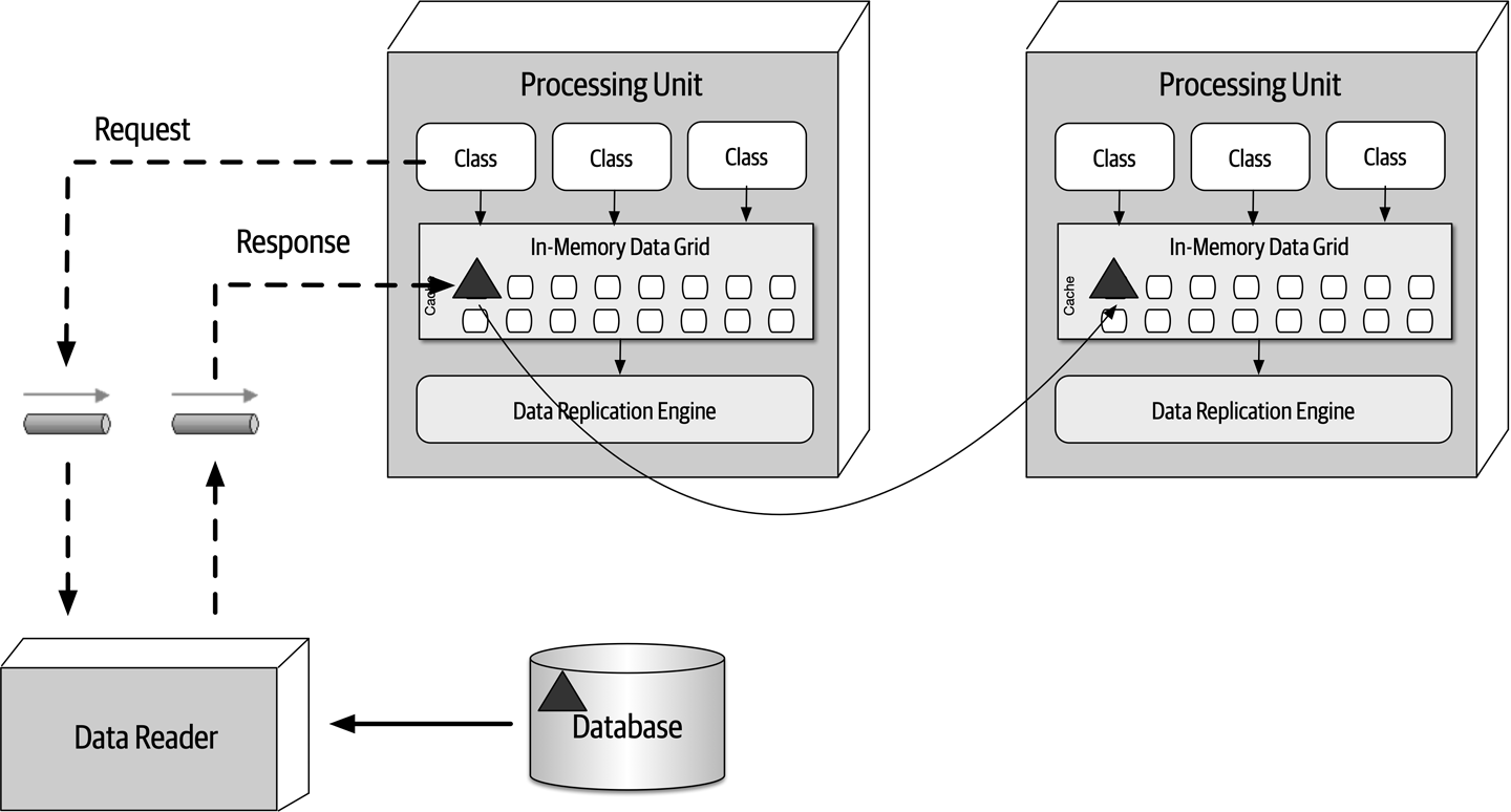
Figure 15-10. Data reader with reverse data pump
Like data writers, data readers can also be domain-based or dedicated to a specific class of processing unit (which is usually the case). The implementation is also the same as the data writers—either service, application, or data hub.
Data Collisions
To illustrate this problem, assume there are two service instances (Service A and Service B) containing a replicated cache of product inventory. The following flow demonstrates the data collision problem:
-
The current inventory count for blue widgets is 500 units
-
Service A updates the inventory cache for blue widgets to 490 units (10 sold)
-
During replication, Service B updates the inventory cache for blue widgets to 495 units (5 sold)
-
The Service B cache gets updated to 490 units due to replication from Service A update
-
The Service A cache gets updates to 495 units due to replication from Service B update
-
Both caches in Service A and B are incorrect and out of sync (inventory should be 485 units)
This formula is useful for determining the percentage of data collisions that will likely occur and hence the feasibility of the use of replicated caching. For example, consider the following values for the factors involved in this calculation:
Update rate (UR): | 20 updates/second |
Number of instances (N): | 5 |
Cache size (S): | 50,000 rows |
Replication latency (RL): | 100 milliseconds |
Updates: | 72,000 per hour |
Collision rate: | 14.4 per hour |
Percentage: | 0.02% |
Applying these factors to the formula yields 72,000 updates and hour, with a high probability that 14 updates to the same data may collide. Given the low percentage (0.02%), replication would be a viable option.
Update rate (UR): | 20 updates/second |
Number of instances (N): | 5 |
Cache size (S): | 50,000 rows |
Replication latency (RL): | 1 millisecond (changed from 100) |
Updates: | 72,000 per hour |
Collision rate: | 0.1 per hour |
Percentage: | 0.0002% |
Update rate (UR): | 20 updates/second |
Number of instances (N): | 2 (changed from 5) |
Cache size (S): | 50,000 rows |
Replication latency (RL): | 100 milliseconds |
Updates: | 72,000 per hour |
Collision rate: | 5.8 per hour |
Percentage: | 0.008% |
Update rate (UR): | 20 updates/second |
Number of instances (N): | 5 |
Cache size (S): | 10,000 rows (changed from 50,000) |
Replication latency (RL): | 100 milliseconds |
Updates: | 72,000 per hour |
Collision rate: | 72.0 per hour |
Percentage: | 0.1% |
Cloud Versus On-Premises Implementations
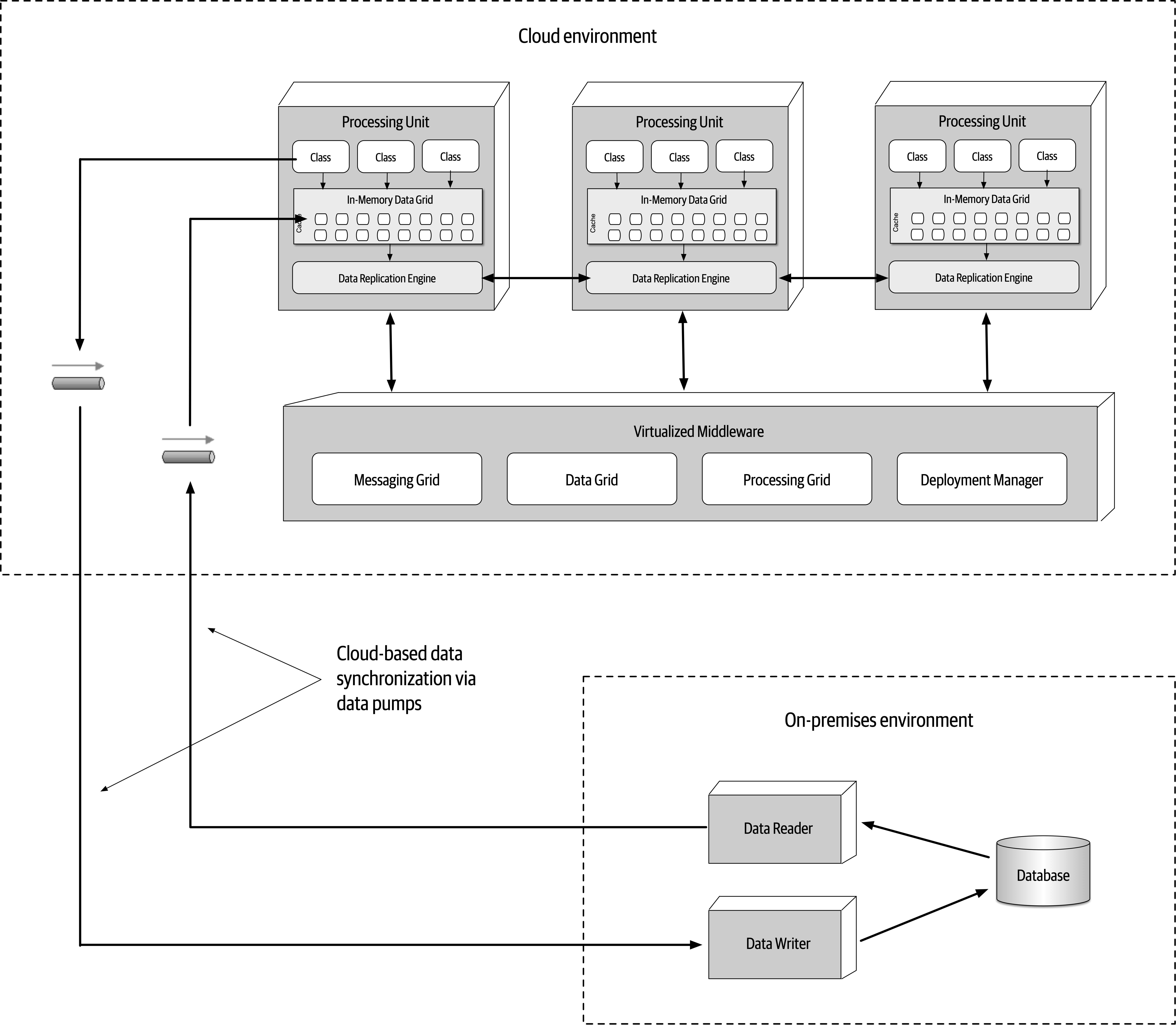
Figure 15-11. Hybrid cloud-based and on-prem topology
Replicated Versus Distributed Caching
Space-based architecture relies on caching for the transactional processing of an application.
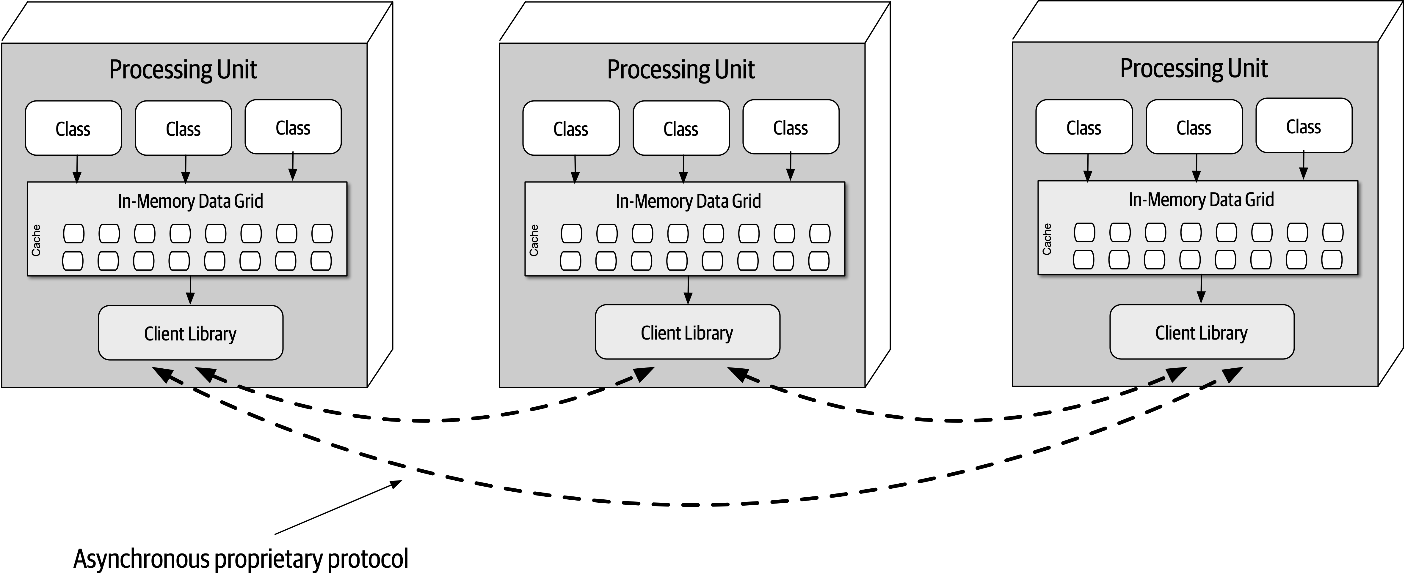
Figure 15-12. Replicated caching between processing units
Replicated caching is not only extremely fast, but it also supports high levels of fault tolerance. Since there is no central server holding the cache, replicated caching does not have a single point of failure. There may be exceptions to this rule, however, based on the implementation of the caching product used. Some caching products require the presence of an external controller to monitor and control the replication of data between processing units, but most product companies are moving away from this model.
While replicated caching is the standard caching model for space-based architecture, there are some cases where it is not possible to use replicated caching. These situations include high data volumes (size of the cache) and high update rates to the cache data. Internal memory caches in excess of 100 MB might start to cause issues with regard to elasticity and high scalability due to the amount of memory used by each processing unit. Processing units are generally deployed within a virtual machine (or in some cases represent the virtual machine). Each virtual machine only has a certain amount of memory available for internal cache usage, limiting the number of processing unit instances that can be started to process high-throughput situations. Furthermore, as shown in “Data Collisions”, if the update rate of the cache data is too high, the data grid might be unable to keep up with that high update rate to ensure data consistency across all processing unit instances. When these situations occur, distributed caching can be used.
Distributed caching, as illustrated in Figure 15-13, requires an external server or service dedicated to holding a centralized cache. In this model the processing units do not store data in internal memory, but rather use a proprietary protocol to access the data from the central cache server. Distributed caching supports high levels of data consistency because the data is all in one place and does not need to be replicated. However, this model has less performance than replicated caching because the cache data must be accessed remotely, adding to the overall latency of the system. Fault tolerance is also an issue with distributed caching. If the cache server containing the data goes down, no data can be accessed or updated from any of the processing units, rendering them nonoperational. Fault tolerance can be mitigated by mirroring the distributed cache, but this could present consistency issues if the primary cache server goes down unexpectedly and the data does not make it to the mirrored cache server.
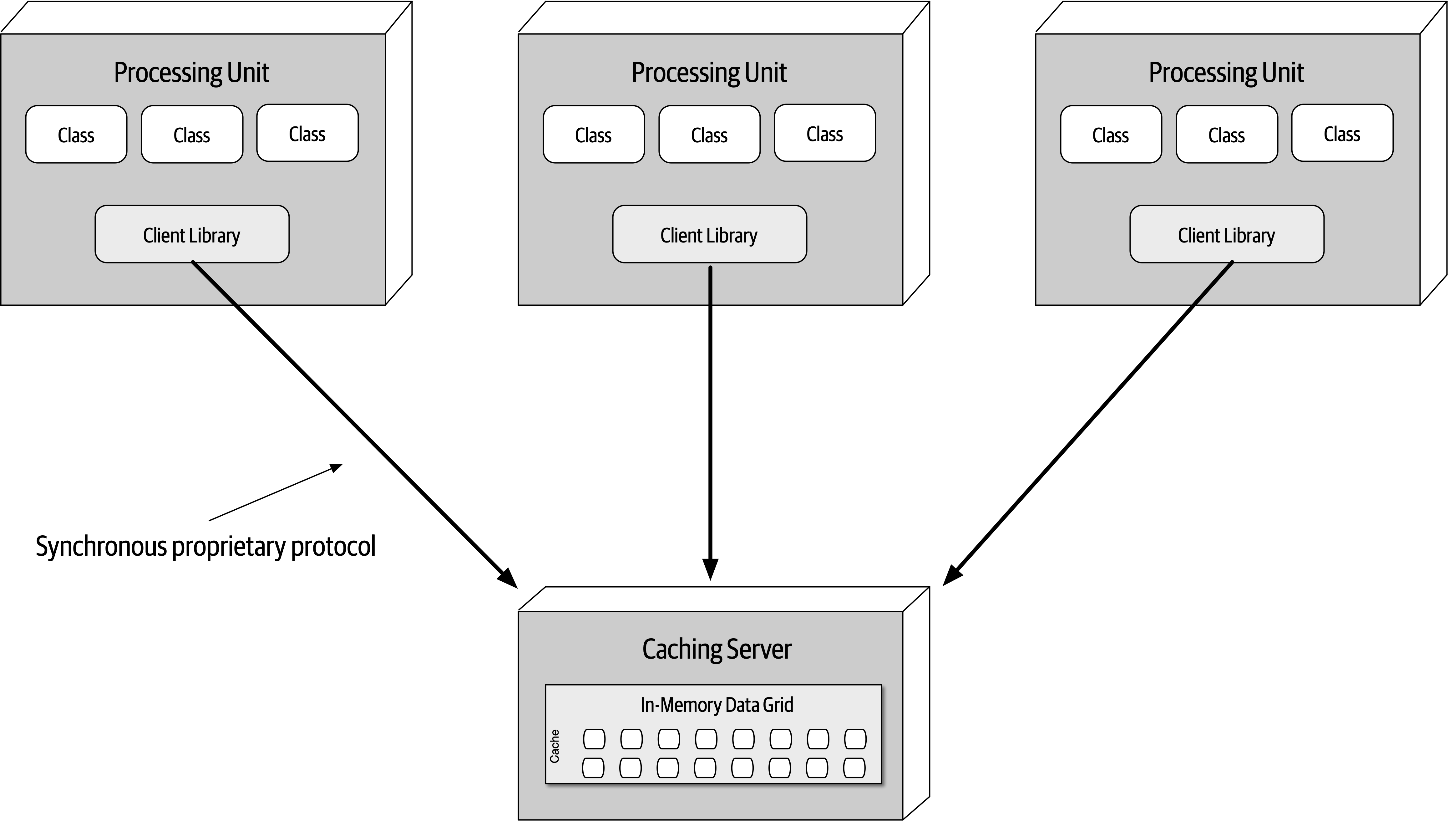
Figure 15-13. Distributed caching between processing units
When the size of the cache is relatively small (under 100 MB) and the update rate of the cache is low enough that the replication engine of the caching product can keep up with the cache updates, the decision between using a replicated cache and a distributed cache becomes one of data consistency versus performance and fault tolerance. A distributed cache will always offer better data consistency over a replicated cache because the cache of data is in a single place (as opposed to being spread across multiple processing units). However, performance and fault tolerance will always be better when using a replicated cache. Many times this decision comes down to the type of data being cached in the processing units. The need for highly consistent data (such as inventory counts of the available products) usually warrants a distributed cache, whereas data that does not change often (such as reference data like name/value pairs, product codes, and product descriptions) usually warrants a replicated cache for quick lookup. Some of the selection criteria that can be used as a guide for choosing when to use a distributed cache versus a replicated cache are listed in Table 15-1.
| Decision criteria | Replicated cache | Distributed cache |
|---|---|---|
Optimization | Performance | Consistency |
Cache size | Small (<100 MB) | Large (>500 MB) |
Type of data | Relatively static | Highly dynamic |
Update frequency | Relatively low | High update rate |
Fault tolerance | High | Low |
When choosing the type of caching model to use with space-based architecture, remember that in most cases both models will be applicable within any given application context. In other words, neither replicated caching nor distributed caching solve every problem. Rather than trying to seek compromises through a single consistent caching model across the application, leverage each for its strengths. For example, for a processing unit that maintains the current inventory, choose a distributed caching model for data consistency; for a processing unit that maintains the customer profile, choose a replicated cache for performance and fault tolerance.
Near-Cache Considerations
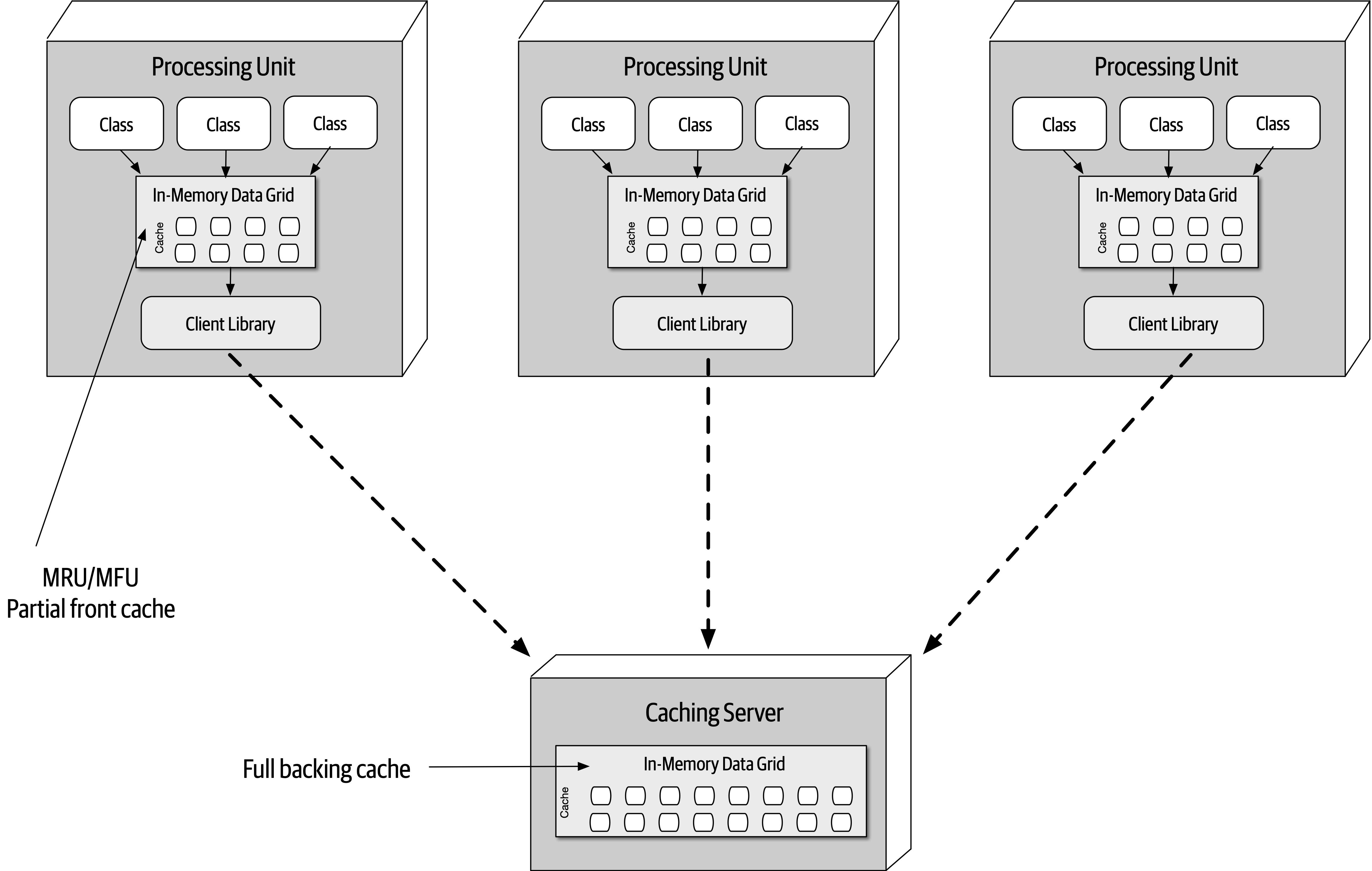
Figure 15-14. Near-cache topology
While the front caches are always kept in sync with the full backing cache, the front caches contained within each processing unit are not synchronized between other processing units sharing the same data. This means that multiple processing units sharing the same data context (such as a customer profile) will likely all have different data in their front cache. This creates inconsistencies in performance and responsiveness between processing units because each processing unit contains different data in the front cache. For this reason we do not recommended using a near-cache model for space-based architecture.
Implementation Examples
Concert Ticketing System
There are many challenges associated with this sort of system. First, there are only a certain number of tickets available, regardless of the seating preferences. Seating availability must continually be updated and made available as fast as possible given the high number of concurrent requests. Also, assuming assigned seats are an option, seating availability must also be updated as fast as possible. Continually accessing a central database synchronously for this sort of system would likely not work—it would be very difficult for a typical database to handle tens of thousands of concurrent requests through standard database transactions at this level of scale and update frequency.
Space-based architecture would be a good fit for a concert ticketing system due to the high elasticity requirements required of this type of application. An instantaneous increase in the number of concurrent users wanting to purchase concert tickets would be immediately recognized by the deployment manager, which in turn would start up a large number of processing units to handle the large volume of requests. Optimally, the deployment manager would be configured to start up the necessary number of processing units shortly before the tickets went on sale, therefore having those instances on standby right before the significant increase in user load.
Online Auction System
Architecture Characteristics Ratings
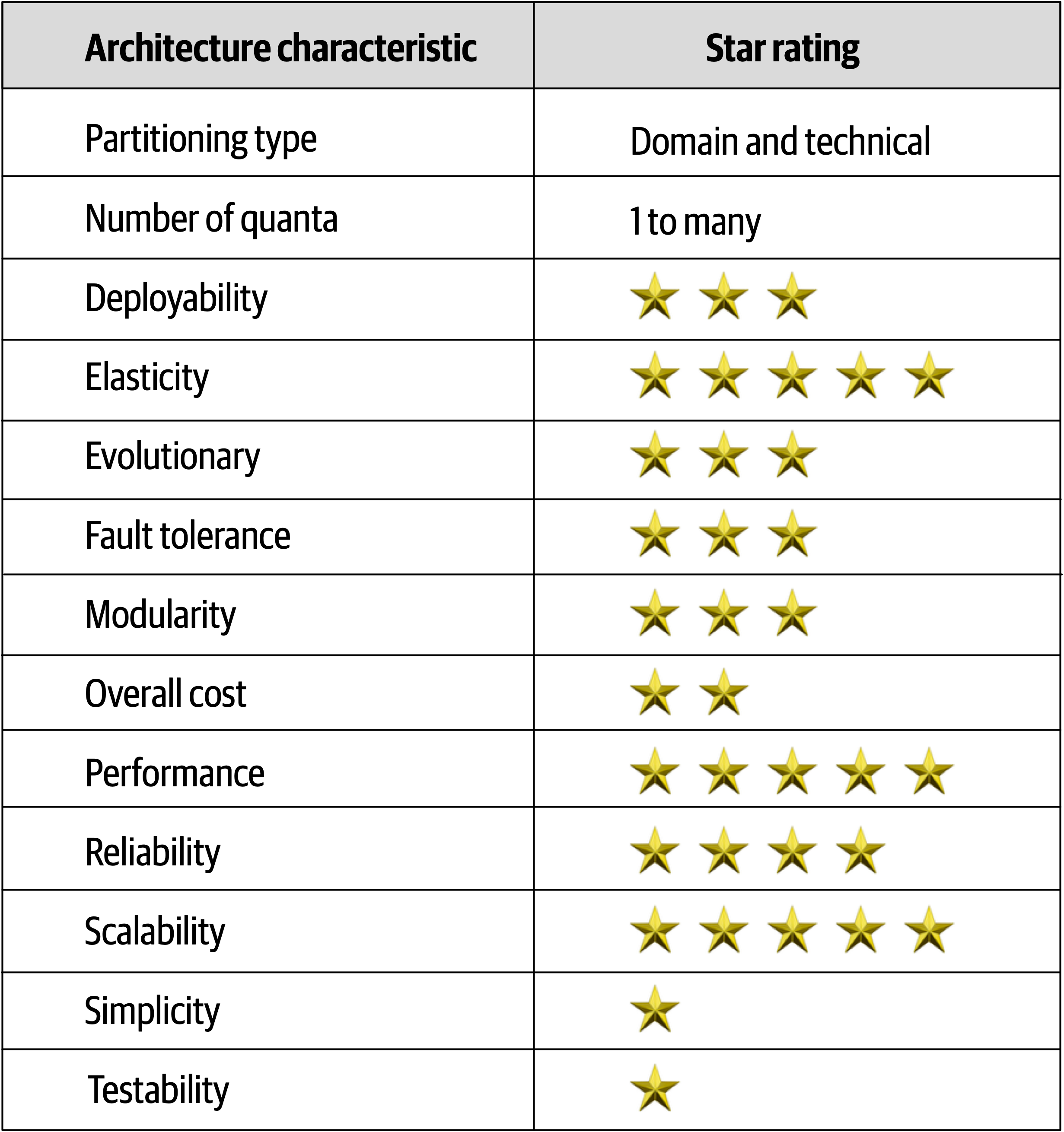
Figure 15-15. Space-based architecture characteristics ratings
Notice that space-based architecture maximizes elasticity, scalability, and performance (all five-star ratings).
Testing gets a one-star rating due to the complexity involved with simulating the high levels of scalability and elasticity supported in this architecture style.
Chapter 16. Orchestration-Driven Service-Oriented Architecture
Architecture styles, like art movements, must be understood in the context of the era in which they evolved, and this architecture exemplifies this rule more than any other.
History and Philosophy
This style of architecture also exemplifies how far architects can push the idea of technical partitioning, which had good motivations but bad consequences.
Topology
The topology of this type of service-oriented architecture
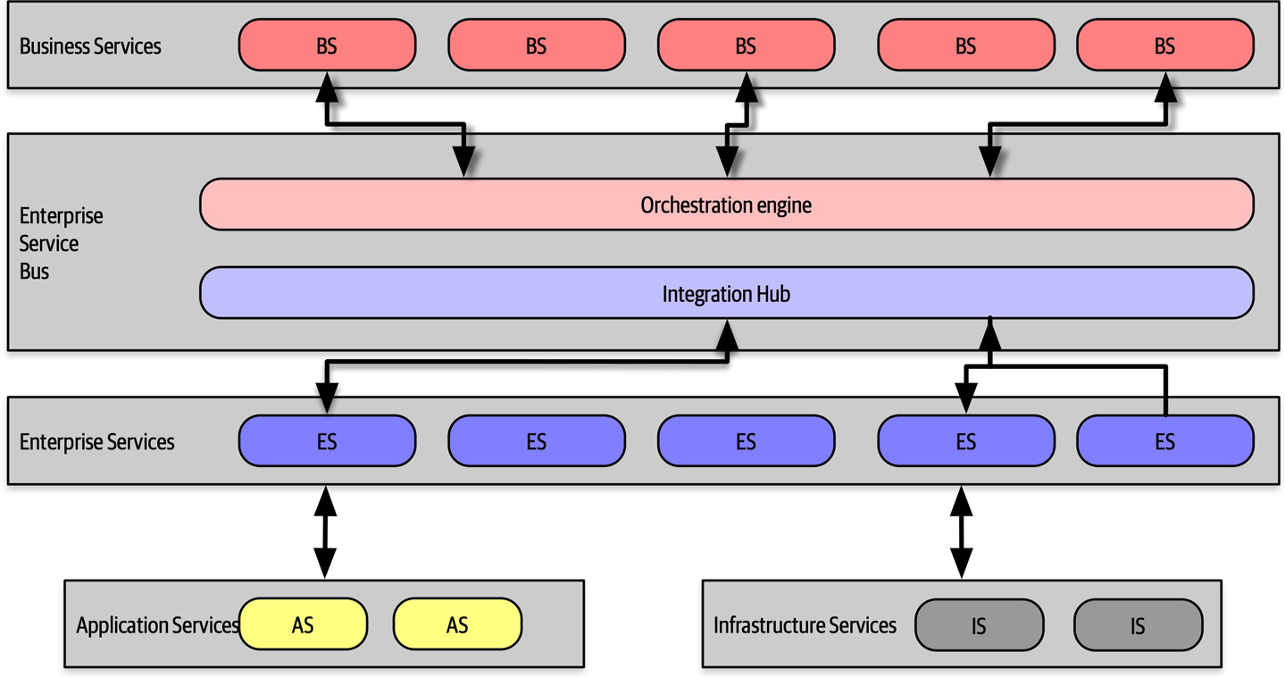
Figure 16-1. Topology of orchestration-driven service-oriented architecture
Not all examples of this style of architecture had the exact layers illustrated in Figure 16-1, but they all followed the same idea of establishing a taxonomy of services within the architecture, each layer with a specific responsibility.
Service-oriented architecture is a distributed architecture; the exact demarcation of boundaries isn’t shown in Figure 16-1 because it varied based on organization.
Taxonomy
The architect’s driving philosophy in this architecture centered around enterprise-level reuse.
Business Services
Business services sit at the top of this architecture and provide the entry point. For example, services like ExecuteTrade or PlaceOrder represent domain behavior. One litmus test common at the time—could an architect answer affirmatively to the question “Are we in the business of…” for each of these services?
These service definitions contained no code—just input, output, and sometimes schema information. They were usually defined by business users, hence the name business services.
Enterprise Services
The enterprise services contain fine-grained, shared implementations. Typically, a team of developers is tasked with building atomic behavior around particular business domains: CreateCustomer, CalculateQuote, and so on. These services are the building blocks that make up the coarse-grained business services, tied together via the orchestration engine.
This separation of responsibility flows from the reuse goal in this architecture. If developers can build fine-grained enterprise services at just the correct level of granularity, the business won’t have to rewrite that part of the business workflow again. Gradually, the business will build up a collection of reusable assets in the form of reusable enterprise services.
Unfortunately, the dynamic nature of reality defies these attempts. Business components aren’t like construction materials, where solutions last decades. Markets, technology changes, engineering practices, and a host of other factors confound attempts to impose stability on the software world.
Application Services
Infrastructure Services
Orchestration Engine
The orchestration engine defines the relationship between the business and enterprise services, how they map together, and where transaction boundaries lie. It also acts as an integration hub, allowing architects to integrate custom code with package and legacy software systems.
While this approach might sound appealing, in practice it was mostly a disaster. Off-loading transaction behavior to an orchestration tool sounded good, but finding the correct level of granularity of transactions became more and more difficult. While building a few services wrapped in a distributed transaction is possible, the architecture becomes increasingly complex as developers must figure out where the appropriate transaction boundaries lie between services.
Message Flow
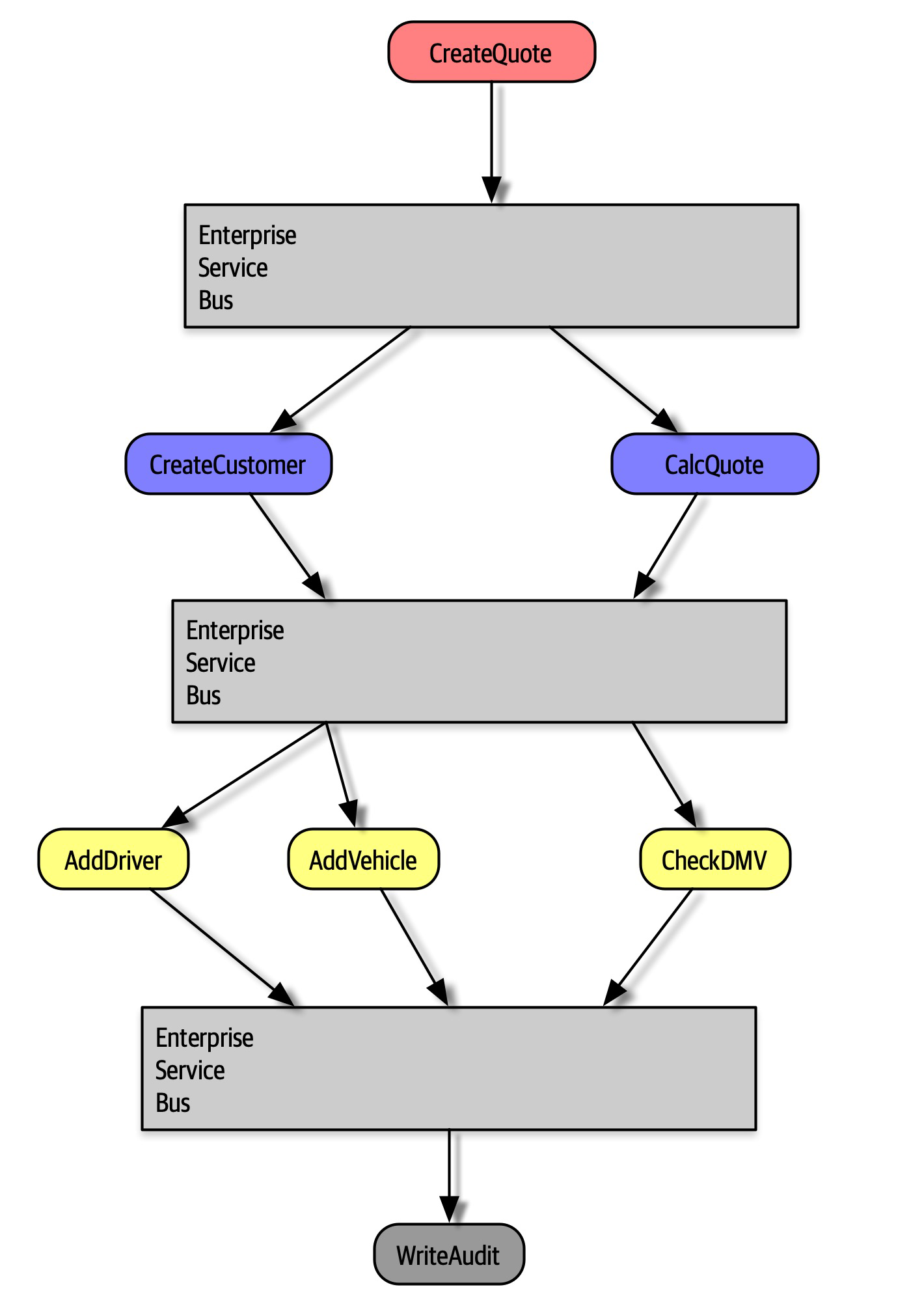
Figure 16-2. Message flow with service-oriented architecture
In Figure 16-2, the CreateQuote business-level service calls the service bus, which defines the workflow that consists of calls to CreateCustomer and CalculateQuote, each of which also has calls to application services. The service bus acts as the intermediary for all calls within this architecture, serving as both an integration hub and orchestration engine.
Reuse…and Coupling
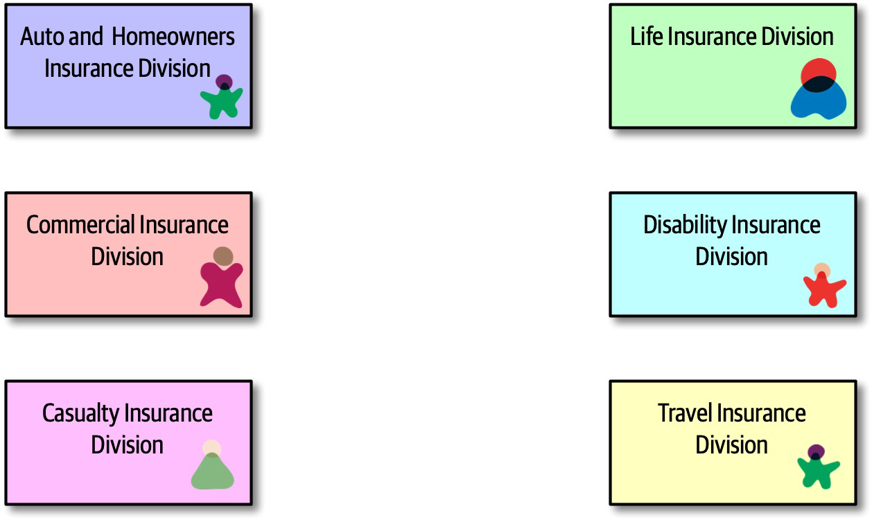
Figure 16-3. Seeking reuse opportunities in service-oriented architecture
In Figure 16-3, an architect realizes that each of these divisions within an insurance company all contain a notion of Customer. Therefore, the proper strategy for service-oriented architecture entails extracting the customer parts into a reusable service and allowing the original services to reference the canonical Customer service, shown in Figure 16-4.
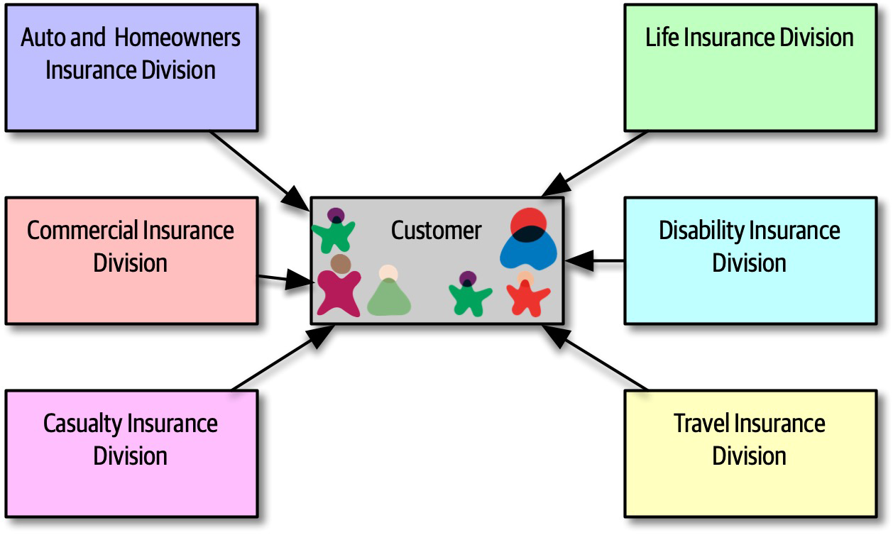
Figure 16-4. Building canonical representations in service-oriented architecture
In Figure 16-4, the architect has isolated all customer behavior into a single Customer service, achieving obvious reuse goals.
However, architects only slowly realized the negative trade-offs of this design. First, when a team builds a system primarily around reuse, they also incur a huge amount of coupling between components.
Customer service ripples out to all the other services, making change risky. Thus, in service-oriented architecture, architects struggled with making incremental change—each change had a potential huge ripple effect. That in turn led to the need for coordinated deployments, holistic testing, and other drags on engineering efficiency. Another negative side effect of consolidating behavior into a single place: consider the case of auto and disability insurance in Figure 16-4. To support a single Customer service, it must include all the details the organization knows about customers. Auto insurance requires a driver’s license, which is a property of the person, not the vehicle. Therefore, the Customer service will have to include details about driver’s licenses that the disability insurance division cares nothing about. Yet, the team that deals with disability must deal with the extra complexity of a single customer definition.
Perhaps the most damaging revelation from this architecture came with the realization of the impractically of building an architecture so focused on technical partitioning.
CatalogCheckout were spread so thinly throughout this architecture that they were virtually ground to dust. Developers commonly work on tasks like “add a new address line to CatalogCheckout.” In a service-oriented architecture, that could entail dozens of services in several different tiers, plus changes to a single database schema. And, if the current enterprise services aren’t defined at the correct transactional granularity, the developers will either have to change their design or build a new, near-identical service to change transactional behavior. So much for reuse.Architecture Characteristics Ratings
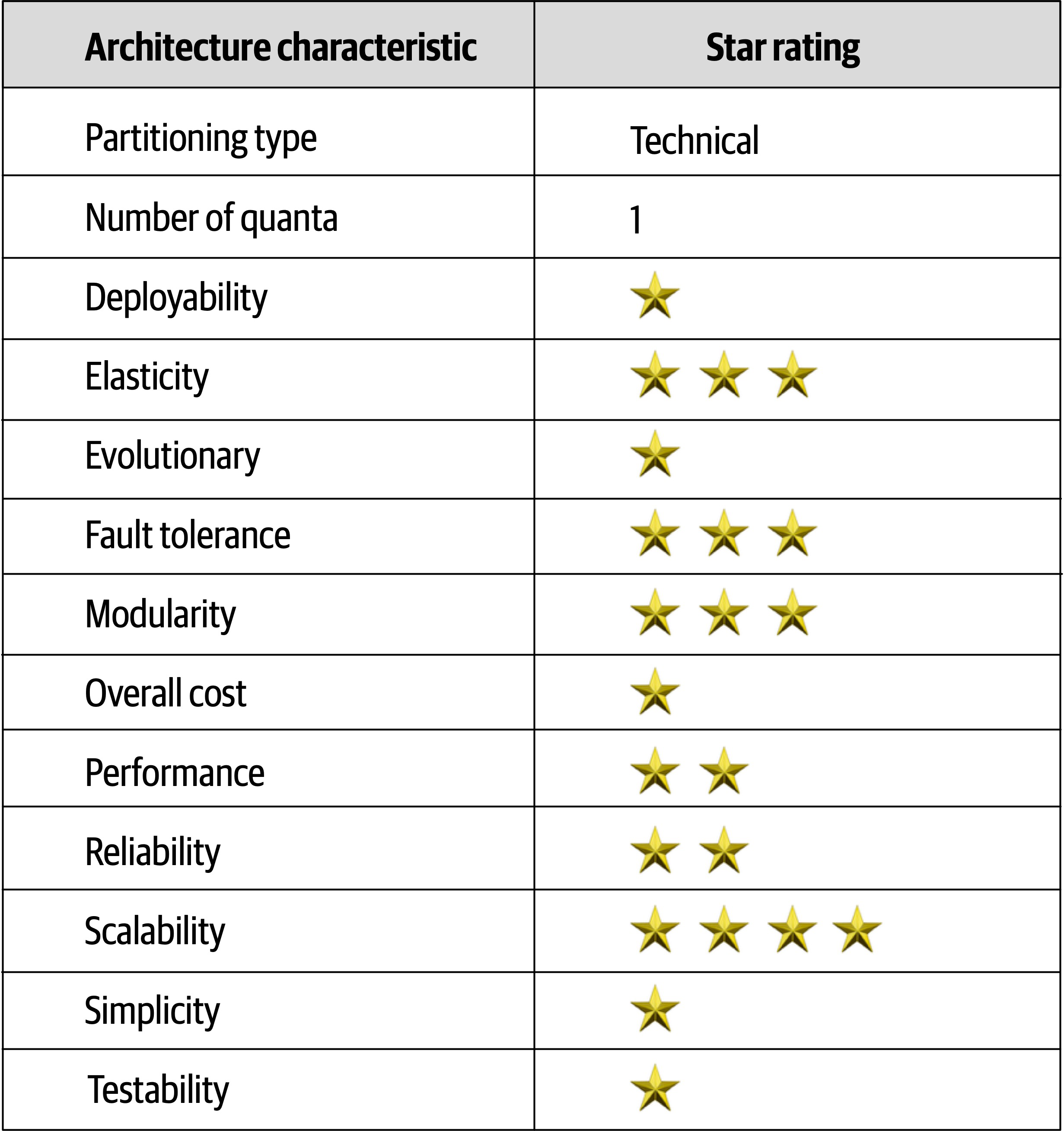
Figure 16-5. Ratings for service-oriented architecture
Service-oriented architecture is perhaps the most technically partitioned general-purpose architecture ever attempted!
Chapter 17. Microservices Architecture
Microservices is an extremely popular architecture style that has gained significant momentum in recent years.
History
CatalogCheckout, which includes notions such as catalog items, customers, and payment. In a traditional monolithic architecture, developers would share many of these concepts, building reusable classes and linked databases. Within a bounded context, the internal parts, such as code and data schemas, are coupled together to produce work; but they are never coupled to anything outside the bounded context, such as a database or class definition from another bounded context. This allows each context to define only what it needs rather than accommodating other constituents.Topology
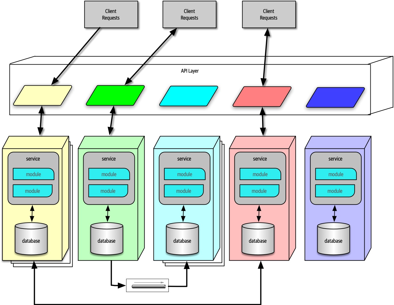
Figure 17-1. The topology of the microservices architecture style
As illustrated in Figure 17-1, due to its single-purpose
Distributed
Performance is often the negative side effect of the distributed nature of microservices. Network calls take much longer than method calls, and security verification at every endpoint adds additional processing time, requiring architects to think carefully about the implications of granularity when designing the system.
Bounded Context
Address, between disparate parts of the application. However, microservices try to avoid coupling, and thus an architect building this architecture style prefers duplication to coupling.Microservices take the concept of a domain-partitioned architecture to the extreme. Each service is meant to represent a domain or subdomain; in many ways, microservices is the physical embodiment of the logical concepts in domain-driven design.
Granularity
The term “microservice” is a label, not a description.
Martin Fowler
In other words, the originators of the term needed to call this new style something, and they chose “microservices” to contrast it with the dominant architecture style at the time, service-oriented architecture, which could have been called “gigantic services”. However, many developers take the term “microservices” as a commandment, not a description, and create services that are too fine-grained.
The purpose of service boundaries in microservices is to capture a domain or workflow. In some applications, those natural boundaries might be large for some parts of the system—some business processes are more coupled than others. Here are some guidelines architects can use to help find the appropriate boundaries:
- Purpose
- The most obvious boundary relies on the inspiration for the architecture style, a domain.Ideally, each microservice should be extremely functionally cohesive, contributing one significant behavior on behalf of the overall application.
- Transactions
- Bounded contexts are business workflows, and often the entities that need to cooperatein a transaction show architects a good service boundary. Because transactions cause issues in distributed architectures, if architects can design their system to avoid them, they generate better designs.
- Choreography
- If an architect builds a set of services that offer excellent domain isolation yet require extensive communication to function, the architect may consider bundling these services back into a larger service to avoid the communication overhead.
Iteration is the only way to ensure good service design. Architects rarely discover the perfect granularity, data dependencies, and communication styles on their first pass. However, after iterating over the options, an architect has a good chance of refining their design.
Data Isolation
Architects are accustomed to using relational databases to unify values within a system, creating a single source of truth, which is no longer an option when distributing data across the architecture. Thus, architects must decide how they want to handle this problem: either identifying one domain as the source of truth for some fact and coordinating with it to retrieve values or using database replication or caching to distribute information.
While this level of data isolation creates headaches, it also provides opportunities. Now that teams aren’t forced to unify around a single database, each service can choose the most appropriate tool, based on price, type of storage, or a host of other factors. Teams have the advantage in a highly decoupled system to change their mind and choose a more suitable database (or other dependency) without affecting other teams, which aren’t allowed to couple to implementation details.
API Layer
Most pictures of microservices include an API layer
While an API layer may be used for variety of things, it should not be used as a mediator or orchestration tool if the architect wants to stay true to the underlying philosophy of this architecture: all interesting logic in this architecture should occur inside a bounded context, and putting orchestration or other logic in a mediator violates that rule.
Operational Reuse
Once a team has built several microservices, they realize that each has common elements that benefit from similarity. For example, if an organization allows each service team to implement monitoring themselves, how can they ensure that each team does so? And how do they handle concerns like upgrades? Does it become the responsibility of each team to handle upgrading to the new version of the monitoring tool, and how long will that take?
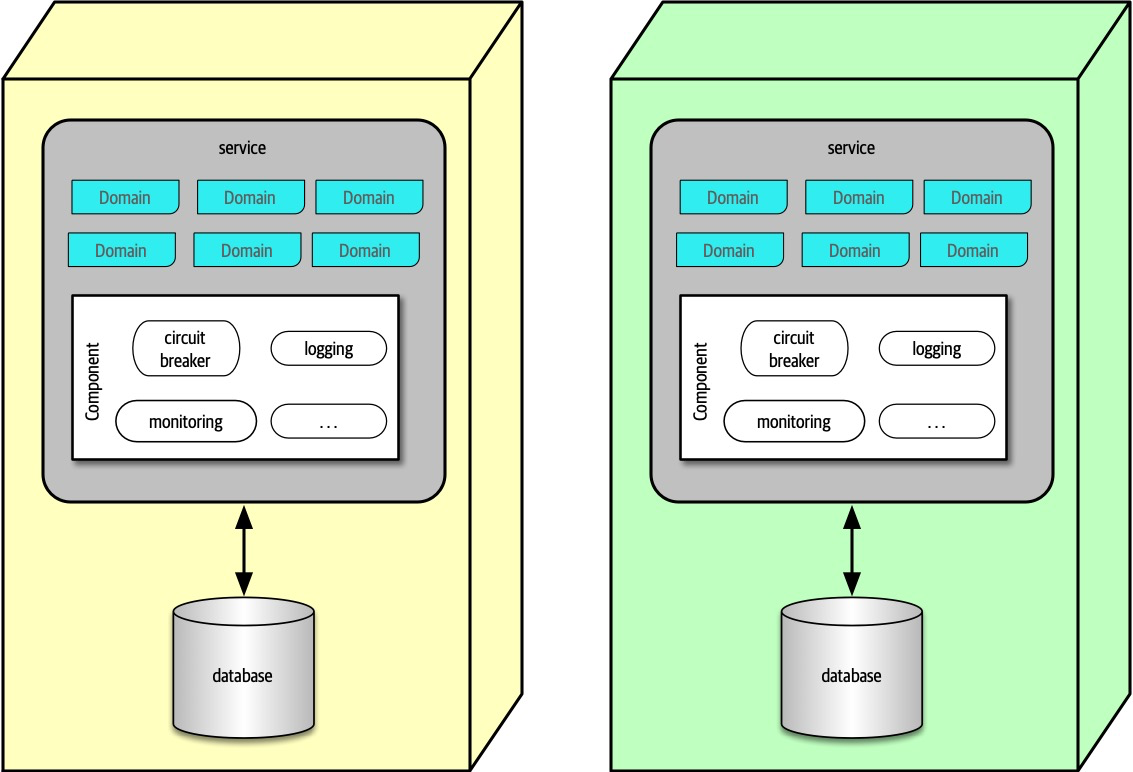
Figure 17-2. The sidecar pattern in microservices
In Figure 17-2, the common operational concerns appear within each service as a separate component, which can be owned by either individual teams or a shared infrastructure team. The sidecar component handles all the operational concerns that teams benefit from coupling together. Thus, when it comes time to upgrade the monitoring tool, the shared infrastructure team can update the sidecar, and each microservices receives that new functionality.
Once teams know that each service includes a common sidecar, they can build a service mesh, allowing unified control across the architecture for concerns like logging and monitoring.
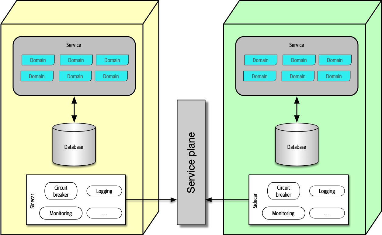
Figure 17-3. The service plane connects the sidecars in a service mesh
In Figure 17-3, each sidecar wires into the service plane, which forms the consistent interface to each service.
The service mesh itself forms a console that allows developers holistic access to services, which is shown in Figure 17-4.
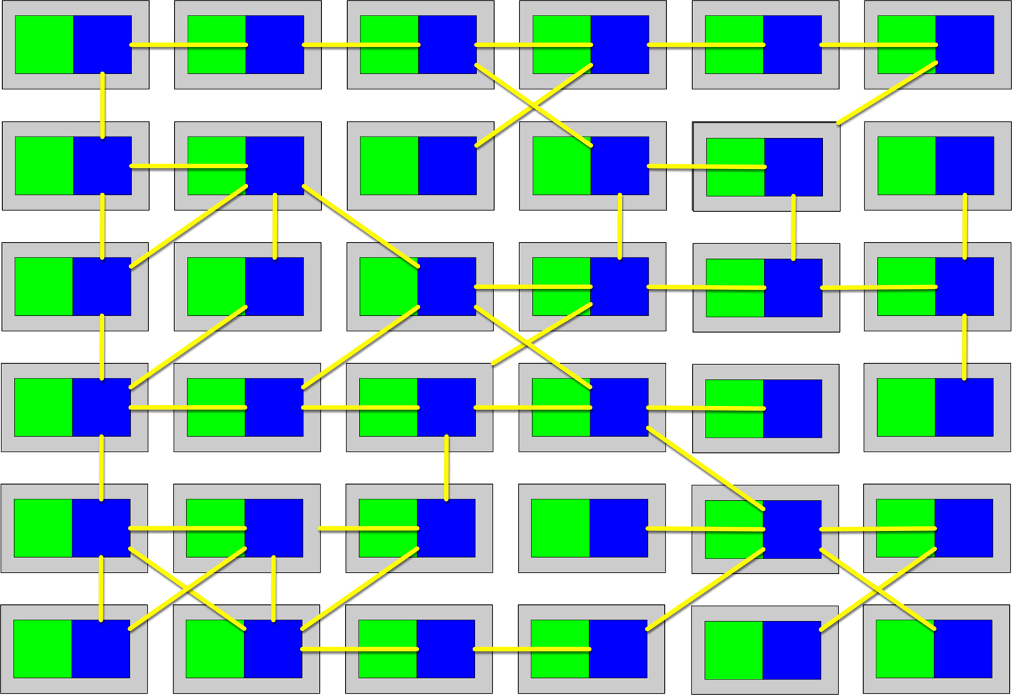
Figure 17-4. The service mesh forms a holistic view of the operational aspect of microservices
Each service forms a node in the overall mesh, as shown in Figure 17-4. The service mesh forms a console that allows teams to globally control operational coupling, such as monitoring levels, logging, and other cross-cutting operational concerns.
Architects use service discovery as a way to build elasticity into microservices architectures.
Frontends
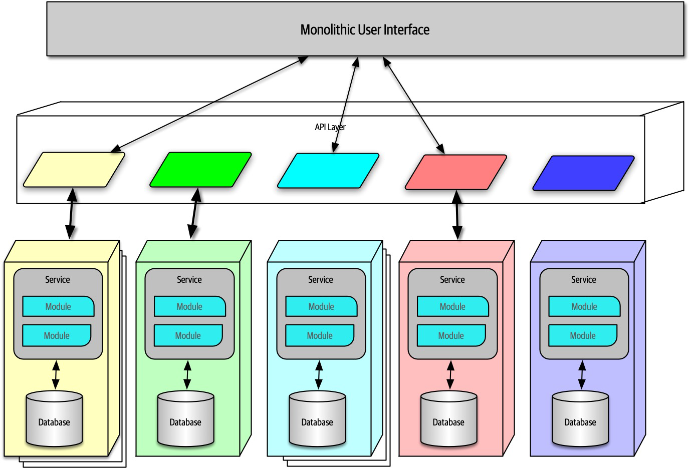
Figure 17-5. Microservices architecture with a monolithic user interface
In Figure 17-5, the monolithic frontend features a single user interface that calls through the API layer to satisfy user requests.
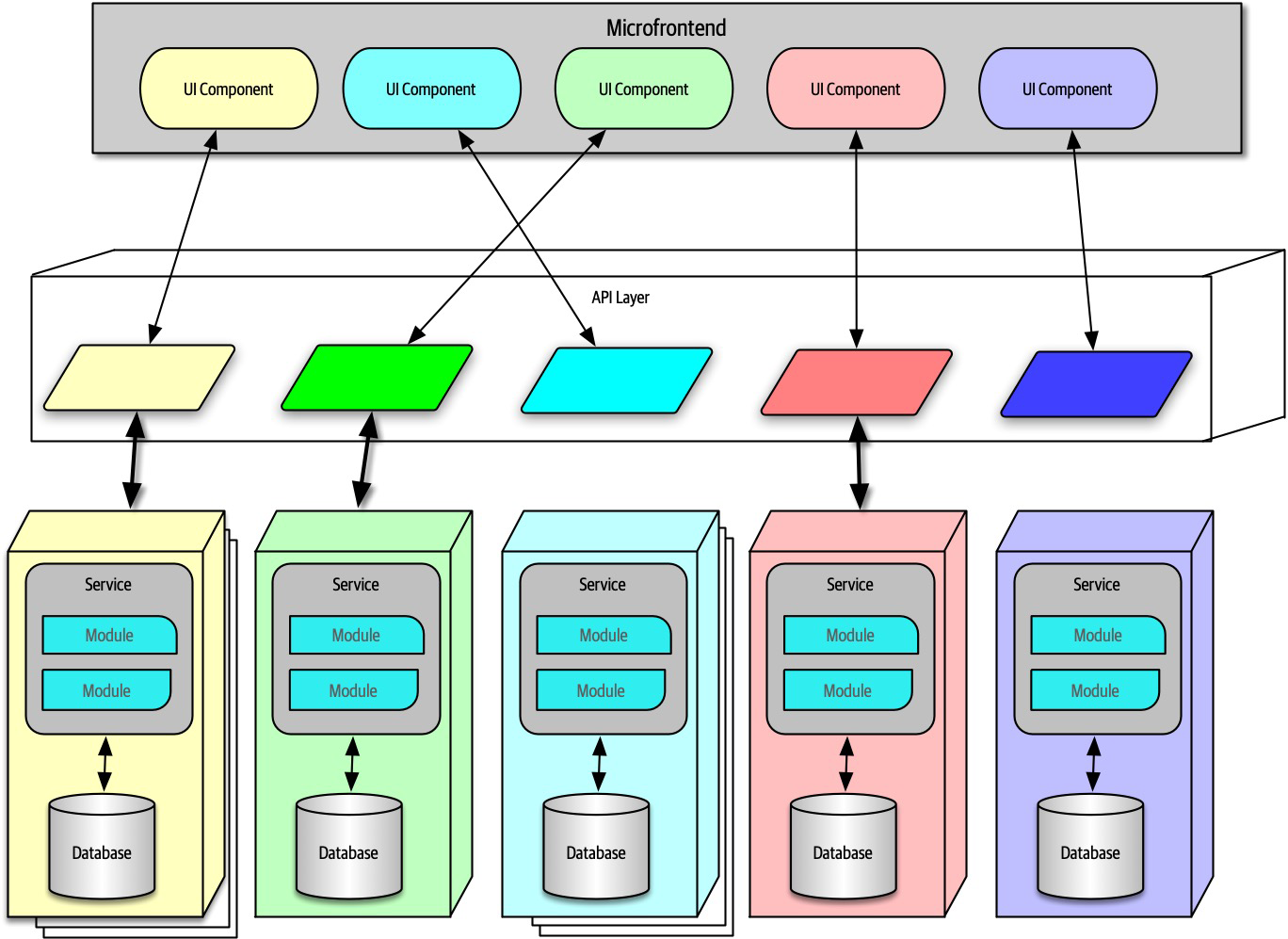
Figure 17-6. Microfrontend pattern in microservices
In Figure 17-6, this approach utilizes components at the user interface level to create a synchronous level of granularity and isolation in the user interface as the backend services. Each service emits the user interface for that service, which the frontend coordinates with the other emitted user interface components. Using this pattern, teams can isolate service boundaries from the user interface to the backend services, unifying the entire domain within a single team.
Developers can implement the microfrontend pattern in a variety of ways, either using a component-based web framework such as React or using one of several open source frameworks that support this pattern.
Communication
- Protocol-aware
-
Because microservices usually don’t include a centralized integration hub to avoid operational coupling, each service should know how to call other services. Thus, architects commonly standardize on how particular services call each other: a certain level of REST, message queues, and so on. That means that services must know (or discover) which protocol to use to call other services.
- Heterogeneous
- Because microservices is a distributed architecture, each service may be written in a different technology stack.Heterogeneous suggests that microservices fully supports polyglot environments, where different services use different platforms.
- Interoperability
- Describes services calling one another.While architects in microservices try to discourage transactional method calls, services commonly call other services via the network to collaborate and send/receive information.
Choreography and Orchestration
Choreography utilizes the same communication style as a broker event-driven architecture.
Similarly, because the architect’s goal in a microservices architecture favors decoupling, the shape of microservices resembles the broker EDA, making these two patterns symbiotic.
In choreography, each service calls other services as needed, without a central mediator. For example, consider the scenario shown in Figure 17-7.
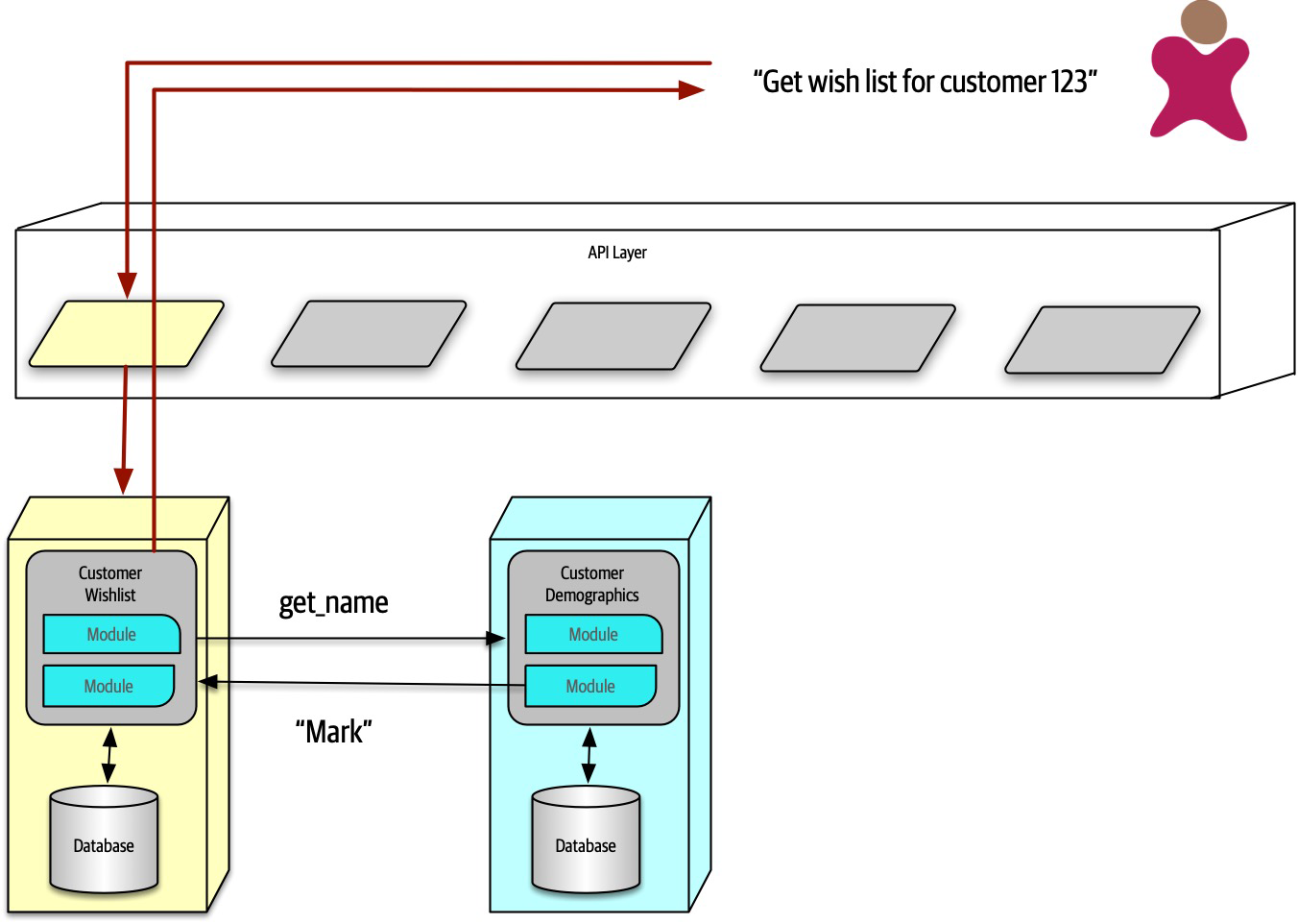
Figure 17-7. Using choreography in microservices to manage coordination
In Figure 17-7, the user requests details about a user’s wish list. Because the CustomerWishList service doesn’t contain all the necessary information, it makes a call to CustomerDemographics to retrieve the missing information, returning the result to the user.
Because microservices architectures don’t include a global mediator like other service-oriented architectures, if an architect needs to coordinate across several services, they can create their own localized mediator, as shown in Figure 17-8.
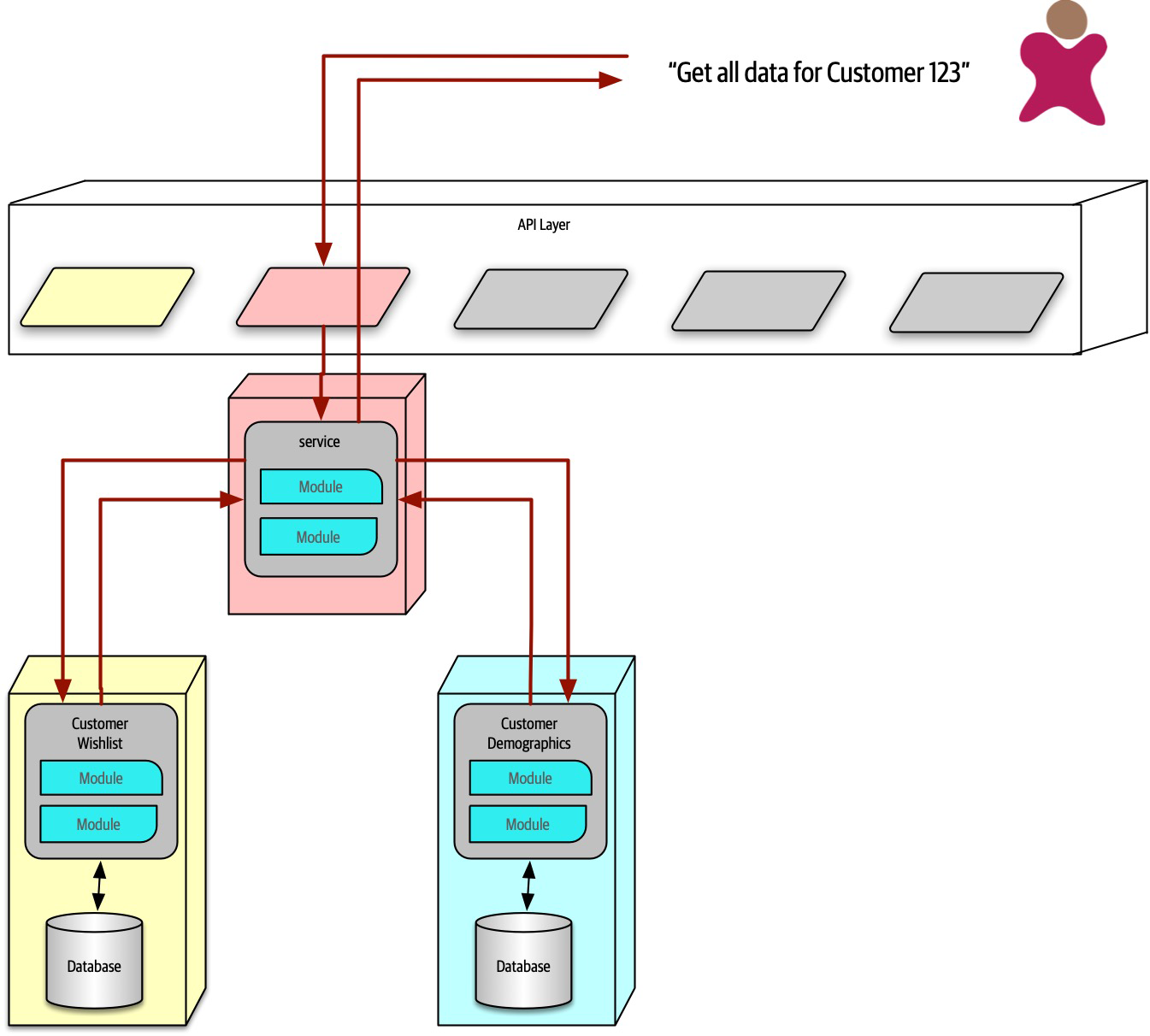
Figure 17-8. Using orchestration in microservices
In Figure 17-8, the developers create a service whose sole responsibility is coordinating the call to get all information for a particular customer. The user calls the ReportCustomerInformation mediator, which calls the necessary other services.
The First Law of Software Architecture suggests that neither of these solutions is perfect—each has trade-offs. In choreography, the architect preserves the highly decoupled philosophy of the architecture style, thus reaping maximum benefits touted by the style. However, common problems like error handling and coordination become more complex in choreographed environments.
Consider an example with a more complex workflow, shown in Figure 17-9.
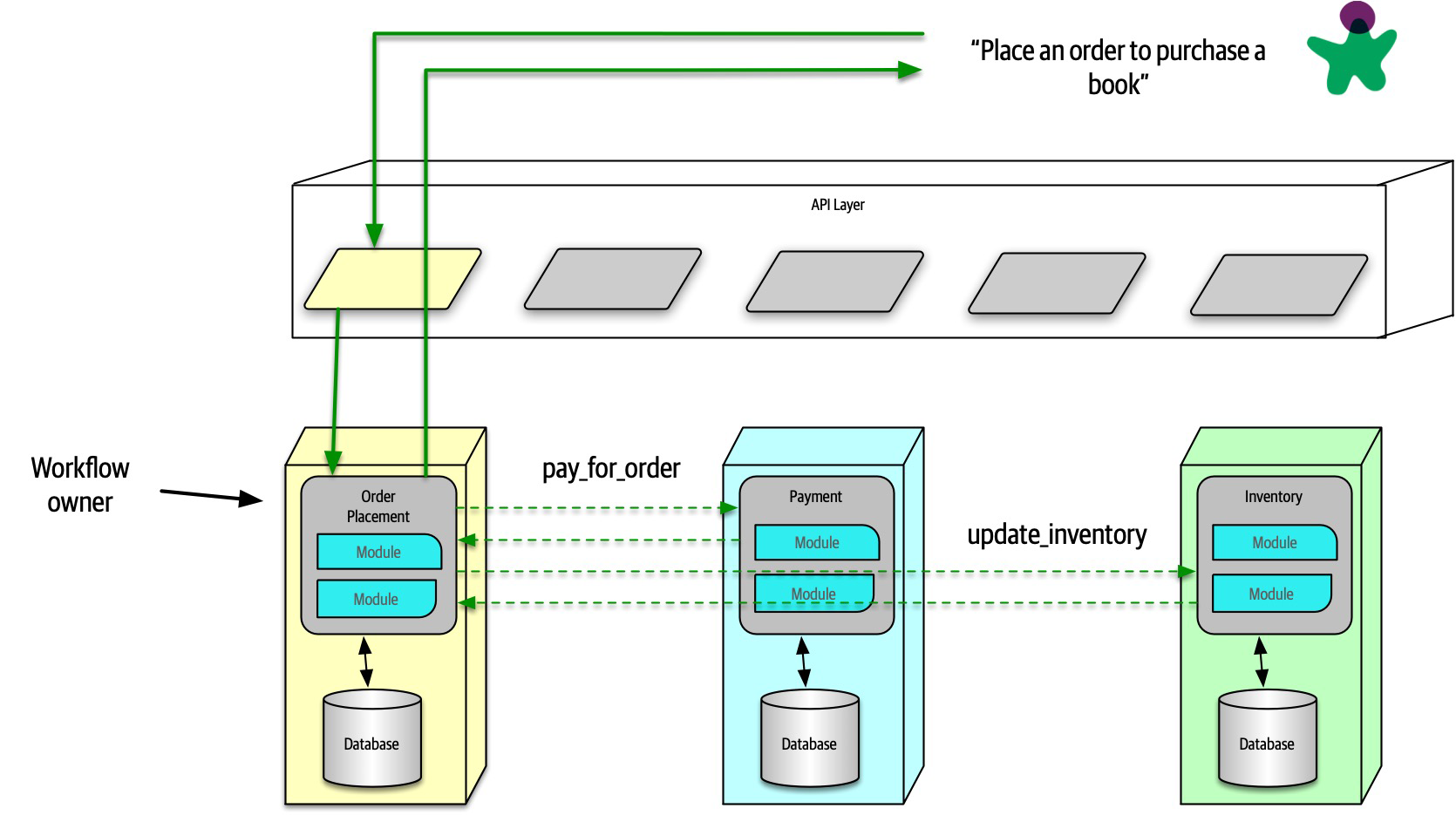
Figure 17-9. Using choreography for a complex business process
In Figure 17-9, the first service called must coordinate across a wide variety of other services, basically acting as a mediator in addition to
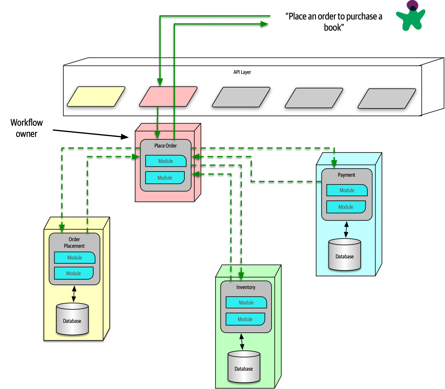
Figure 17-10. Using orchestration for a complex business process
In Figure 17-10, the architect builds a mediator to handle the complexity and coordination required for the business workflow. While this creates coupling between these services, it allows the architect to focus coordination into a single service, leaving the others less affected. Often, domain workflows are inherently coupled—the architect’s job entails finding the best way to represent that coupling in ways that support both the domain and architectural goals.
Transactions and Sagas
Building transactions across service boundaries violates the core decoupling principle of the microservices architecture (and also creates the worst kind of dynamic connascence, connascence of value). The best advice for architects who want to do transactions across services is: don’t! Fix the granularity components instead. Often, architects who build microservices architectures who then find a need to wire them together with transactions have gone too granular in their design. Transaction boundaries is one of the common indicators of service granularity.
Tip
Don’t do transactions in microservices—fix granularity instead!
Exceptions always exist. For example, a situation may arise where two different services need vastly different architecture characteristics, requiring distinct service boundaries, yet still need transactional coordination. In those situations, patterns exist to handle transaction orchestration, with serious trade-offs.
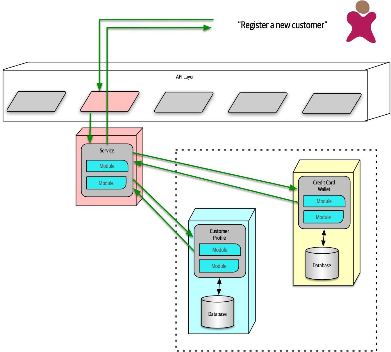
Figure 17-11. The saga pattern in microservices architecture
In Figure 17-11, a service acts a mediator across multiple service calls and coordinates the transaction. The mediator calls each part of the transaction, records success or failure, and coordinates results. If everything goes as planned, all the values in the services and their contained databases update synchronously.
In an error condition, the mediator must ensure that no part of the transaction succeeds if one part fails. Consider the situation shown in Figure 17-12.
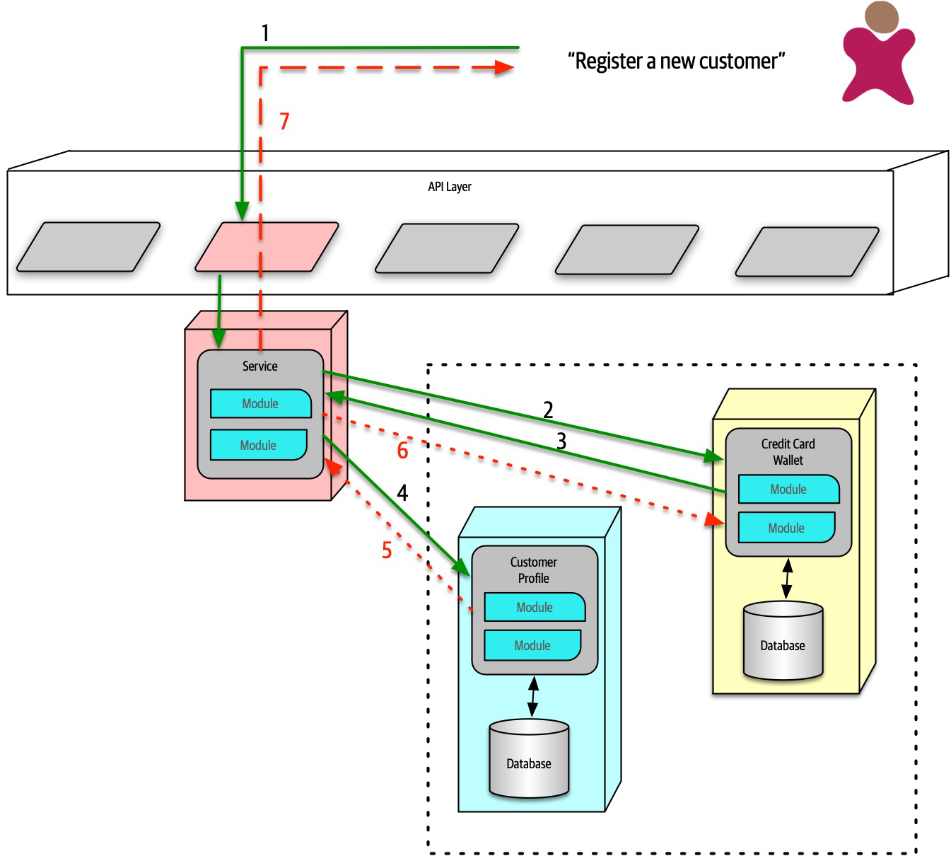
Figure 17-12. Saga pattern compensating transactions for error conditions
In Figure 17-12, if the first part of the transaction succeeds, yet the second part fails, the mediator must send a request to all the parts of the transaction that were successful and tell them to undo the previous request.
pending state until the mediator indicates overall success. However, this design becomes complex if asynchronous requests must be juggled, especially if new requests appear that are contingent on pending transactional state. This also creates a lot of coordination traffic at the network level.While it is possible for architects to build transactional behavior across services, it goes against the reason for choosing the microservices pattern. Exceptions always exist, so the best advice for architects is to use the saga pattern sparingly.
Tip
Architecture Characteristics Ratings
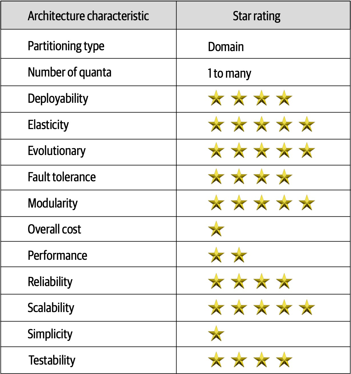
Figure 17-13. Ratings for microservices
Notable in the ratings in Figure 17-13 is the high support for modern engineering practices such as automated deployment, testability, and others not listed.
Additional References
- Building Microservices by Sam Newman (O’Reilly)
-
Microservices vs. Service-Oriented Architecture by Mark Richards (O’Reilly)
-
Microservices AntiPatterns and Pitfalls by Mark
Richards (O’Reilly)
Chapter 18. Choosing the Appropriate Architecture Style
It depends! With all the choices available (and new ones arriving almost daily), we would like to tell you which one to use—but we cannot.
However contextual the decision is, some general advice exists around choosing an appropriate architecture style.
Shifting “Fashion” in Architecture
- Observations from the past
-
New architecture styles generally arise from observations and pain points from past experiences. Architects have experience with systems in the past that influence their thoughts about future systems. Architects must rely on their past experience—it is that experience that allowed that person to become an architect in the first place. Often, new architecture designs reflect specific deficiencies from past architecture styles. For example, architects seriously rethought the implications of code reuse after building architectures that featured it and then realizing the negative trade-offs.
- Changes in the ecosystem
- Constant change is a reliable feature of the software development ecosystem—everything changes all the time.The change in our ecosystem is particularly chaotic, making even the type of change impossible to predict. For example, a few years ago, no one knew what Kubernetes was, and now there are multiple conferences around the world with thousands of developers.In a few more years, Kubernetes may be replaced with some other tool that hasn’t been written yet.
- New capabilities
- When new capabilities arise, architecture may not merely replace one tool with another but rather shift to an entirely new paradigm.For example, few architects or developers anticipated the tectonic shift caused in the software development world by the advent of containers such as Docker. While it was an evolutionary step, the impact it had on architects, tools, engineering practices, and a host of other factors astounded most in the industry. The constant change in the ecosystem also delivers a new collection of tools and capabilities on a regular basis. Architects must keep a keen eye open to not only new tools but new paradigms. Something may just look like a new one-of-something-we-already-have, but it may include nuances or other changes that make it a game changer. New capabilities don’t even have to rock the entire development world—the new features may be a minor change that aligns exactly with an architect’s goals.
- Acceleration
- Not only does the ecosystem constantly change, but the rate of change also continues to rise.New tools create new engineering practices, which lead to new design and capabilities. Architects live in a constant state of flux because change is both pervasive and constant.
- Domain changes
- The domain that developers write software for constantly shifts and changes, either because the business continues to evolve or because of factors like mergers with other companies.
- Technology changes
- As technology continues to evolve, organizations try to keep up with at least some of these changes, especially those with obvious bottom-line benefits.
- External factors
-
Many external factors only peripherally associated with software development may drive change within an organizations. For example, architects and developers might be perfectly happy with a particular tool, but the licensing cost has become prohibitive, forcing a migration to another option.
Decision Criteria
Architects should go into the design decision comfortable with the following things:
- The domain
-
Architects should understand many important aspects of the domain, especially those that affect operational architecture characteristics. Architects don’t have to be subject matter experts, but they must have at least a good general understanding of the major aspects of the domain under design.
- Architecture characteristics that impact structure
-
Architects must discover and elucidate the architecture characteristics needed to support the domain and other eternal factors.
- Data architecture
-
Architects and DBAs must collaborate on database, schema, and other data-related concerns. We don’t cover much about data architecture in this book; it is its own specialization. However, architects must understand the impact that data design might have on their design, particularly if the new system must interact with an older and/or in-use data architecture.
- Organizational factors
-
Many external factors may influence design. For example, the cost of a particular cloud vendor may prevent the ideal design. Or perhaps the company plans to engage in mergers and acquisitions, which encourages an architect to gravitate toward open solutions and integration architectures.
- Knowledge of process, teams, and operational concerns
-
Many specific project factors influence an architect’s design, such as the software development process, interaction (or lack of) with operations, and the QA process. For example, if an organization lacks maturity in Agile engineering practices, architecture styles that rely on those practices for success will present difficulties.
- Domain/architecture isomorphism
-
Some problem domains match the topology of the architecture. For example, the microkernel architecture style is perfectly suited to a system that requires customizability—the architect can design customizations as plug-ins. Another example might be genome analysis, which requires a large number of discrete operations, and space-based architecture, which offers a large number of discrete processors.
Similarly, some problem domains may be particularly ill-suited for some architecture styles. For example, highly scalable systems struggle with large monolithic designs because architects find it difficult to support a large number of concurrent users in a highly coupled code base. A problem domain that includes a huge amount of semantic coupling matches poorly with a highly decoupled, distributed architecture. For instance, an insurance company application consisting of multipage forms, each of which is based on the context of previous pages, would be difficult to model in microservices. This is a highly coupled problem that will present architects with design challenges in a decoupled architecture; a less coupled architecture like service-based architecture would suit this problem better.
Taking all these things into account, the architect must make several determinations:
- Monolith versus distributed
- Using the quantum concepts discussed earlier,the architect must determine if a single set of architecture characteristics will suffice for the design, or do different parts of the system need differing architecture characteristics? A single set implies that a monolith is suitable (although other factors may drive an architect toward a distributed architecture), whereas different architecture characteristics imply a distributed architecture.
- Where should data live?
- If the architecture is monolithic, architects commonly assume a single relational databases or a few of them.In a distributed architecture, the architect must decide which services should persist data, which also implies thinking about how data must flow throughout the architecture to build workflows. Architects must consider both structure and behavior when designing architecture and not be fearful of iterating on the design to find better combinations.
- What communication styles between services—synchronousor asynchronous?
- Once the architect has determined data partitioning, their next design consideration is the communication between services—synchronous or asynchronous? Synchronous communication is more convenient in most cases, but it can lead to scalability, reliability, and other undesirable characteristics.Asynchronous communication can provide unique benefits in terms of performance and scale but can present a host of headaches: data synchronization, deadlocks, race conditions, debugging, and so on.
Because synchronous communication presents fewer design, implementation, and debugging challenges, architects should default to synchronous when possible and use asynchronous when necessary.
Tip
Use synchronous by default, asynchronous when necessary.
Monolith Case Study: Silicon Sandwiches
Modular Monolith
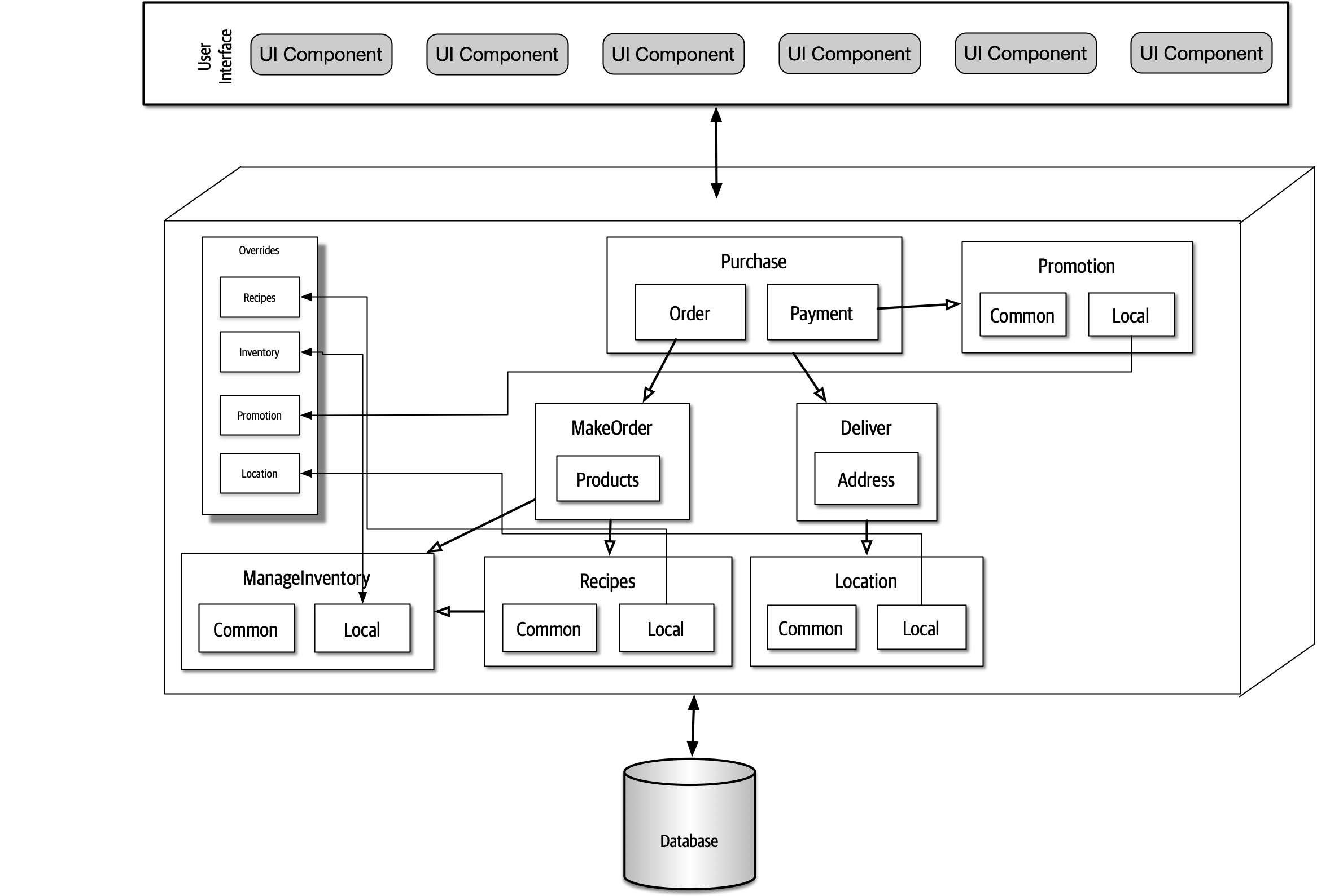
Figure 18-1. A modular monolith implementation of Silicon Sandwiches
In Figure 18-1, this is a monolith with a single relational database, implemented with a single web-based user interface (with careful design considerations for mobile devices) to keep overall cost down. Each of the domains the architect identified earlier appear as components. If time and resources are sufficient, the architect should consider creating the same separation of tables and other database assets as the domain components, allowing for this architecture to migrate to a distributed architecture more easily if future requirements warrant it.
Because the architecture style itself doesn’t inherently handle customization, the architect must make sure that that feature becomes part of domain design. In this case, the architect designs an Override endpoint where developers can upload individual customizations. Correspondingly, the architect must ensure that each of the domain components references the Override component for each customizable characteristic—this would make a perfect fitness function.
Microkernel
One of the architecture characteristics the architect identified in Silicon Sandwiches was customizability.
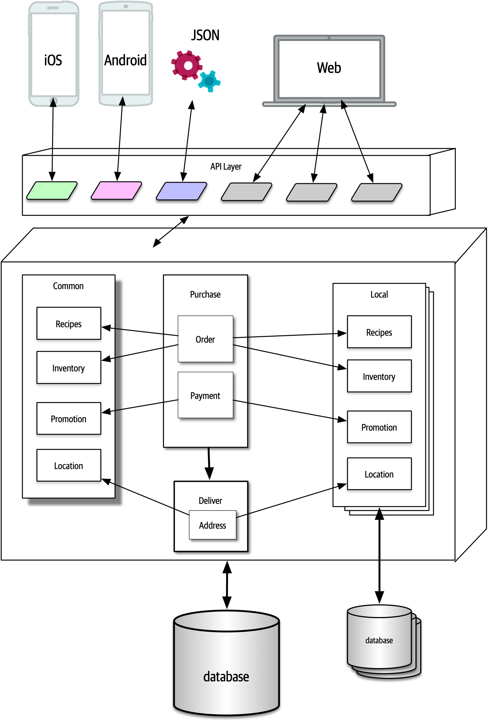
Figure 18-2. A microkernel implementation of Silicon Sandwiches
In Figure 18-2, the core system consists of the domain components and a single relational database. As in the previous design, careful synchronization between domains and data design will allow future migration of the core to a distributed architecture.
Distributed Case Study: Going, Going, Gone
The requirements for GGG also explicitly state certain ambitious levels of scale, elasticity, performance, and a host of other tricky operational architecture characteristics. The architect needs to choose a pattern that allows for a high degree of customization at a fine-grained level within the architecture. Of the candidate distributed architectures, either low-level event-driven or microservices match most of the architecture characteristics. Of the two, microservices better supports differing operational architecture characteristics—purely event-driven architectures typically don’t separate pieces because of these operational architecture characteristics but are rather based on communication style, orchestrated versus choreographed.
Achieving the stated performance will provide a challenge in microservices, but architects can often address any weak point of an architecture by designing to accommodate it. For example, while microservices offers a high degrees of scalability naturally, architects commonly have to address specific performance issues caused by too much orchestration, too aggressive data separation, and so on.
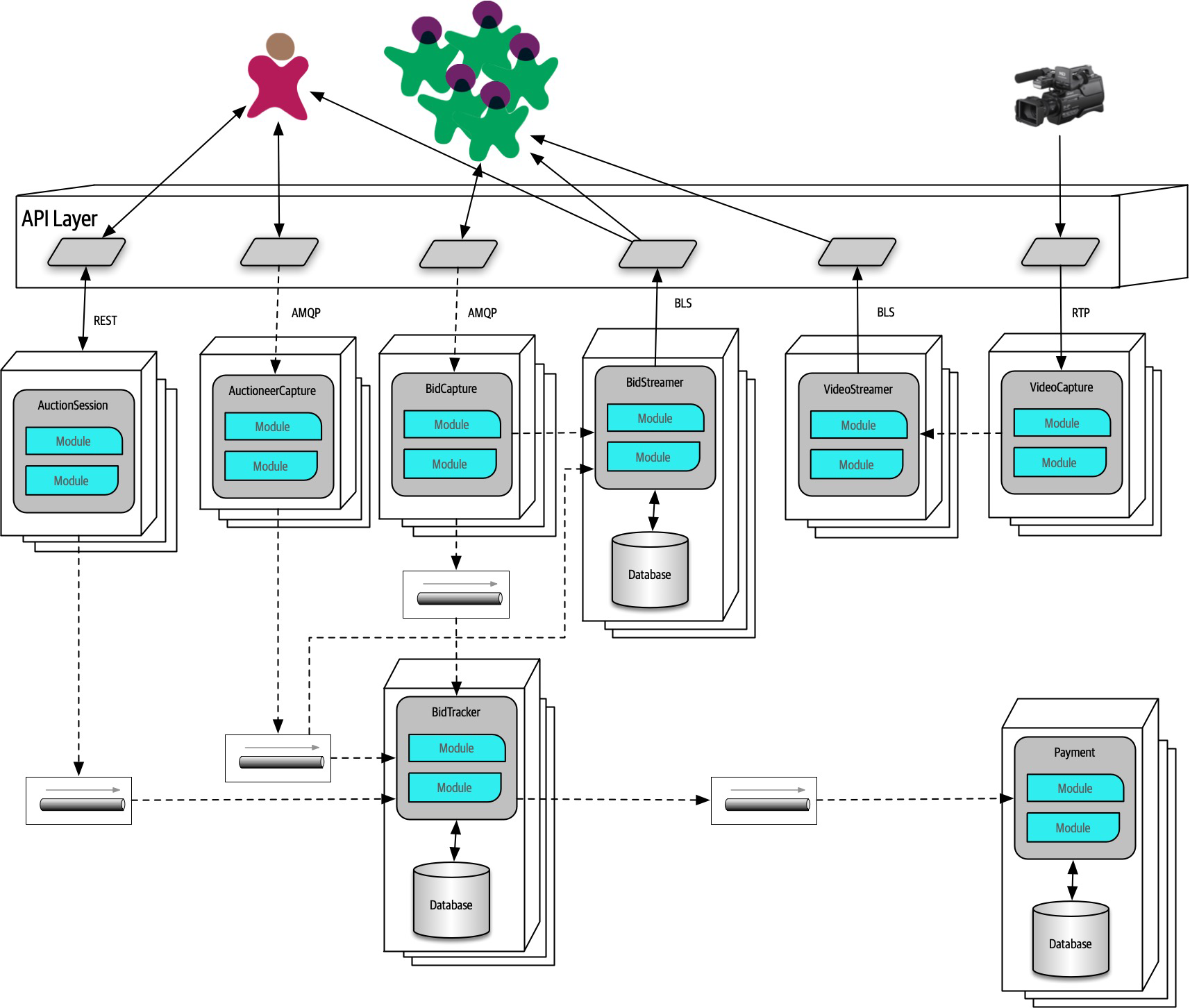
Figure 18-3. A microservices implementation of Going, Going, Gone
In Figure 18-3, each identified component became services in the architecture, matching component and service granularity.
- Bidder
-
The numerous bidders for the online auction.
- Auctioneer
-
One per auction.
- Streamer
-
Service responsible for streaming video and bid stream to the bidders. Note that this is a read-only stream, allowing optimizations not available if updates were necessary.
BidCapture-
Captures online bidder entries and asynchronously sends them to
Bid Tracker. This service needs no persistence because it acts as a conduit for the online bids. BidStreamer-
Streams the bids back to online participants in a high performance, read-only stream.
BidTracker-
Tracks bids from both
Auctioneer CaptureandBid Capture. This is the component that unifies the two different information streams, ordering the bids as close to real time as possible. Note that both inbound connections to this service are asynchronous, allowing the developers to use message queues as buffers to handle very different rates of message flow. Auctioneer Capture- Captures bids for the auctioneer. The result of quanta analysis in“Case Study: Going, Going, Gone: Discovering Components” led the architect to separate
Bid CaptureandAuctioneer Capturebecause they have quite different architecture characteristics. Auction Session-
This manages the workflow of individual auctions.
Payment-
Third-party payment provider that handles payment information after the
AuctionSessionhas completed the auction. Video Capture-
Captures the video stream of the live auction.
Video Streamer-
Streams the auction video to online bidders.
The architect was careful to identify both synchronous and asynchronous communication styles in this architecture.
Payment service can only process a new payment every 500 ms and a large number of auctions end at the same time, synchronous communication between the services would cause time outs and other reliability headaches. By using message queues, the architect can add reliability to a critical part of the architecture that exhibits fragility.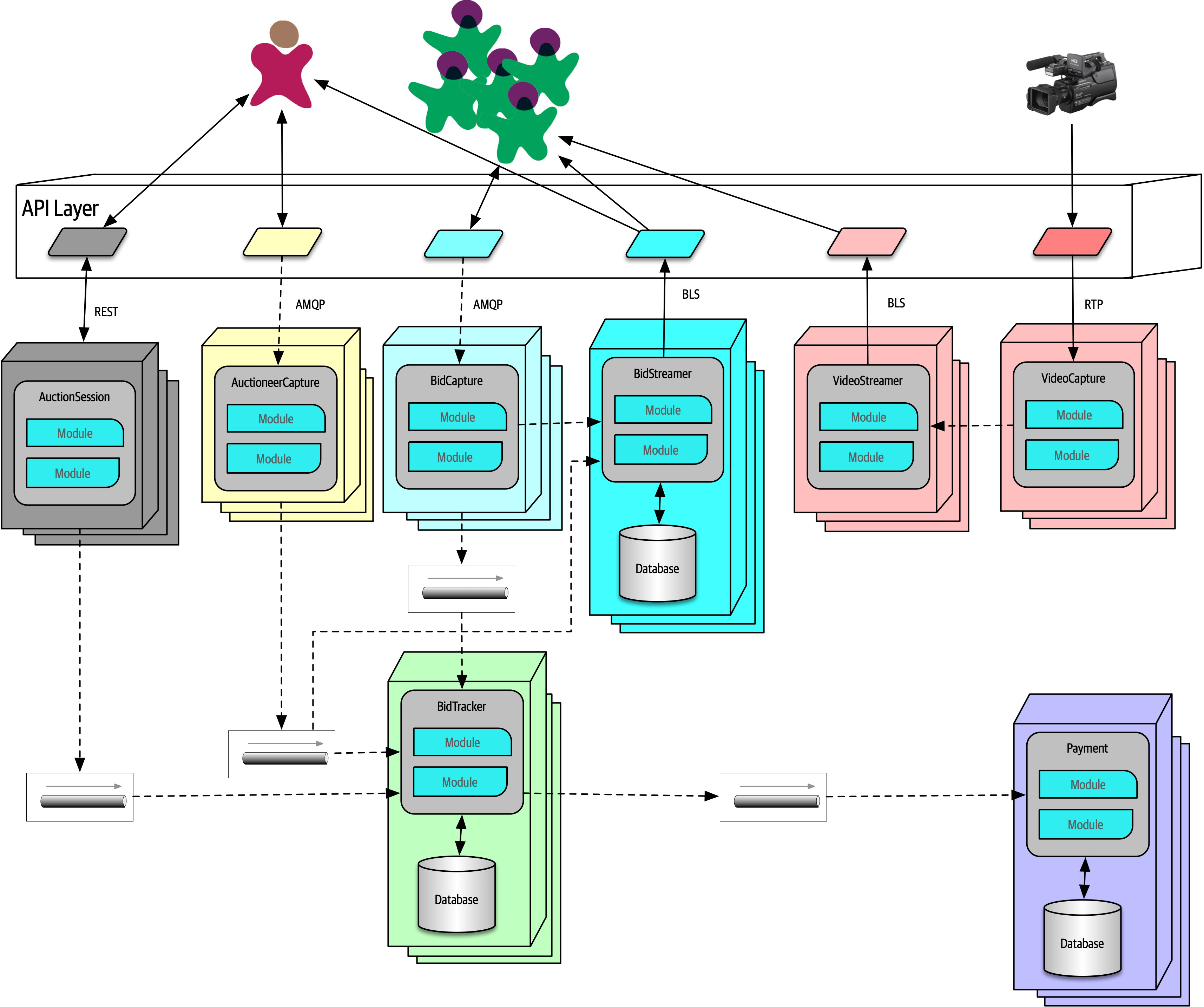
Figure 18-4. The quanta boundaries for GGG
In Figure 18-4, the design includes quanta for Payment, Auctioneer, Bidder, Bidder Streams, and Bid Tracker, roughly corresponding to the services. Multiple instances are indicated by stacks of containers in the diagram. Using quantum analysis at the component design stage allowed the architect to more easily identify service, data, and communication boundaries.
Note that this isn’t the “correct” design for GGG, and it’s certainly not the only one. We don’t even suggest that it’s the best possible design, but it seems to have the least worst set of trade-offs. Choosing microservices, then intelligently using events and messages, allows the architecture to leverage the most out of a generic architecture pattern while still building a foundation for future development and expansion.
Part III. Techniques and Soft Skills
An effective software architect must not only understand the technical aspects of software architecture, but also the primary techniques and soft skills necessary to think like an architect, guide development teams, and effectively communicate the architecture to various stakeholders. This section of the book addresses the key techniques and soft skills necessary to become an effective software architect.
Chapter 19. Architecture Decisions
One of the core expectations of an architect is to make architecture decisions. Architecture decisions usually involve the structure
Architecture Decision Anti-Patterns
Covering Your Assets Anti-Pattern
The first anti-pattern to emerge when trying to make architecture decisions is the Covering Your Assets anti-pattern.
There are two ways to overcome this anti-pattern. The first is to wait until the last responsible moment to make an important architecture decision. The last responsible moment means waiting until you have enough information to justify and validate your decision, but not waiting so long that you hold up development teams or fall into the Analysis Paralysis anti-pattern. The second way to avoid this anti-pattern is to continually collaborate with development teams to ensure that the decision you made can be implemented as expected. This is vitally important because it is not feasible as an architect to possibly know every single detail about a particular technology and all the associated issues. By closely collaborating with development teams, the architect can respond quickly to a change in the architecture decision if issues occur.
To illustrate this point, suppose an architect makes the decision that all product-related reference data (product description, weight, and dimensions) be cached in all service instances needing that information using a read-only replicated cache, with the primary replica owned by the catalog service. A replicated cache means that if there are any changes to product information (or a new product is added), the catalog service would update its cache, which would then be replicated to all other services requiring that data through a replicated (in-memory) cache product. A good justification for this decision is to reduce coupling between the services and to effectively share data without having to make an interservice call. However, the development teams implementing this architecture decision find that due to certain scalability requirements of some of the services, this decision would require more in-process memory than is available. By closely collaborating with the development teams, the architect can quickly become aware of the issue and adjust the architecture decision to accommodate these situations.
Groundhog Day Anti-Pattern
Providing the business value when justifying decisions is vitally important for any architecture decision. It is also a good litmus test for determining whether the architecture decision should be made in the first place. If a particular architecture decision does not provide any business value, then perhaps it is not a good decision and should be reconsidered.
Email-Driven Architecture Anti-Pattern
The second rule of effectively communicating architecture decisions is to only notify those people who really care about the architecture decision. One effective technique is to write the body of the email as follows:
“Hi Sandra, I’ve made an important decision regarding communication between services that directly impacts you. Please see the decision using the following link…”
Architecturally Significant
Architecture Decision Records
Tooling is
Basic Structure
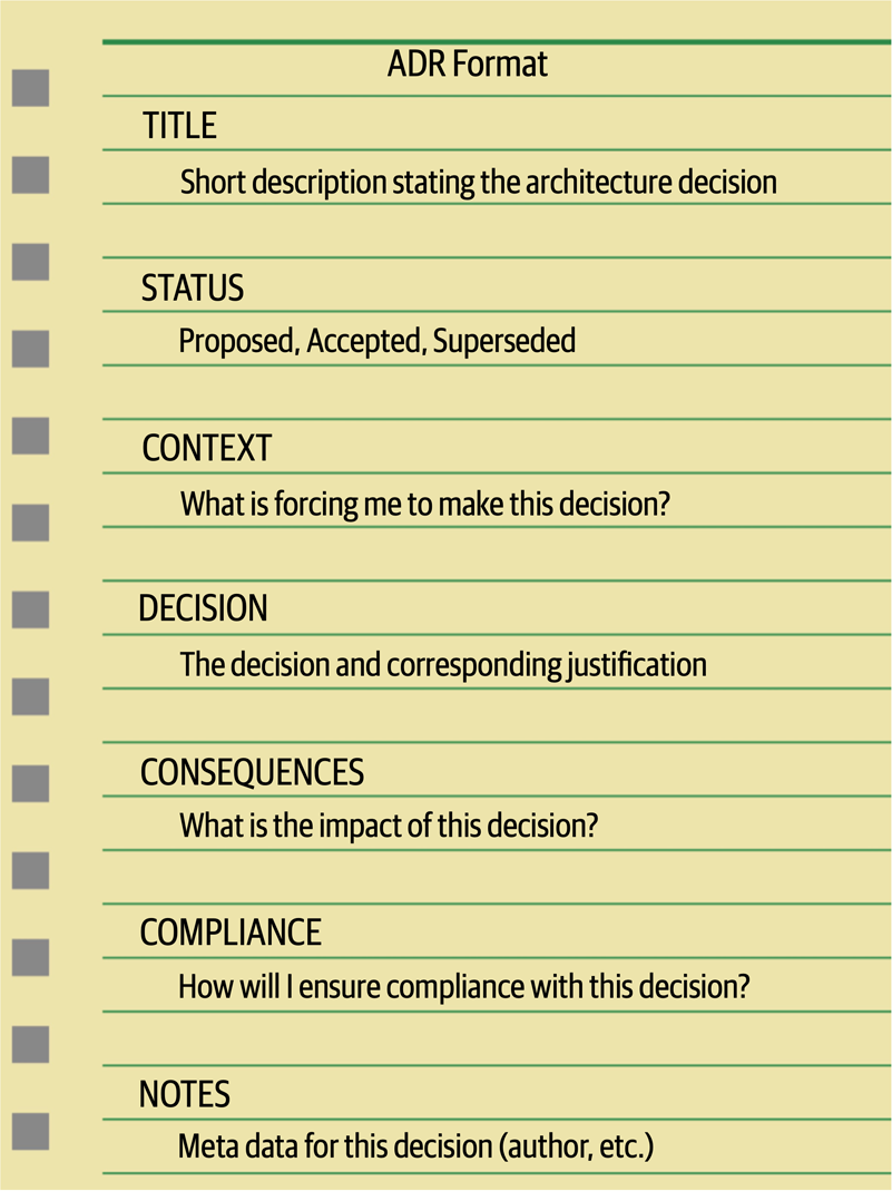
Figure 19-1. Basic ADR structure
Title
The title of an ADR is usually numbered sequentially and contains a short phase describing the architecture decisions.
Status
The Superseded status is a powerful way of keeping a historical record of what decisions were made, why they were made at that time, and what the new decision is and why it was changed. Usually, when an ADR has been superseded, it is marked with the decision that superseded it. Similarly, the decision that supersedes another ADR is marked with the ADR it superseded. For example, assume ADR 42 (“Use of Asynchronous Messaging Between Order and Payment Services”) was previously approved, but due to later changes to the implementation and location of the Payment Service, REST must now be used between the two services (ADR 68). The status would look as follows:
ADR 42. Use of Asynchronous Messaging Between Order and Payment Services
Status: Superseded by 68
ADR 68. Use of REST Between Order and Payment Services
Status: Accepted, supersedes 42
The link and history trail between ADRs 42 and 68 avoid the inevitable “what about using messaging?” question regarding ADR 68.
Another significant aspect of the Status section of an ADR is that it forces an architect to have necessary conversations with their boss or lead architect about the criteria with which they can approve an architecture decision on their own, or whether it must be approved through a higher-level architect, an architecture review board, or some other architecture governing body.
Three criteria that form a good start for these conversations are cost, cross-team impact, and security. Cost can include software purchase or licensing fees, additional hardware costs, as well as the overall level of effort to implement the architecture decision. Level of effort costs can be estimated by multiplying the estimated number of hours to implement the architecture decision by the company’s standard Full-Time Equivalency (FTE) rate. The project owner or project manager usually has the FTE amount. If the cost of the architecture decision exceeds a certain amount, then it must be set to Proposed status and approved by someone else. If the architecture decision impacts other teams or systems or has any sort of security implication, then it cannot be self-approved by the architect and must be approved by a higher-level governing body or lead architect.
Once the criteria and corresponding limits have been established and agreed upon (such as “costs exceeding €5,000 must be approved by the architecture review board”), this criteria should be well documented so that all architects creating ADRs know when they can and cannot approve their own architecture decisions.
Context
The Context section also provides a way to document the architecture. By describing the context, the architect is also describing the architecture. This is an effective way of documenting a specific area of the architecture in a clear and concise manner. Continuing with the example from the prior section, the context might read as follows: “The order service must pass information to the payment service to pay for an order currently being placed. This could be done using REST or asynchronous messaging.” Notice that this concise statement not only specified the scenario, but also the alternatives.
Decision
Perhaps one of the most powerful aspects of the Decision section of ADRs is that it allows an architect to place more emphasis on the why rather than the how. Understanding why a decision was made is far more important than understanding how something works. Most architects and developers can identify how things work by looking at context diagrams, but not why a decision was made. Knowing why a decision was made and the corresponding justification for the decision helps people better understand the context of the problem and avoids possible mistakes through refactoring to another solution that might produce issues.
Consequences
The Consequences section of an ADR is another very powerful section. This section documents the overall impact of an architecture decision. Every architecture decision an architect makes has some sort of impact, both good and bad. Having to specify the impact of an architecture decision forces the architect to think about whether those impacts outweigh the benefits of the decision.
Another good use of this section is to document the trade-off analysis associated with the architecture decision. These trade-offs could be cost-based or trade-offs against other architecture characteristics (“-ilities”). For example, consider the decision to use asynchronous (fire-and-forget) messaging to post a review on a website. The justification for this decision is to significantly increase the responsiveness of the post review request from 3,100 milliseconds to 25 milliseconds because users would not need to wait for the actual review to be posted (only for the message to be sent to a queue). While this is a good justification, someone else might argue that this is a bad idea due to the complexity of the error handling associated with an asynchronous request (“what happens if someone posts a review with some bad words?”). Unknown to the person challenging this decision, that issue was already discussed with the business stakeholders and other architects, and it was decided from a trade-off perspective that it was more important to have the increase in responsiveness and deal with the complex error handling rather than have the wait time to synchronously provide feedback to the user that the review was successfully posted. By leveraging ADRs, that trade-off analysis can be included in the Consequences section, providing a complete picture of the context (and trade-offs) of the architecture decision and thus avoiding these situations.
Compliance
The compliance section of an ADR is not one of the standard sections in an ADR, but it’s one we highly recommend adding.
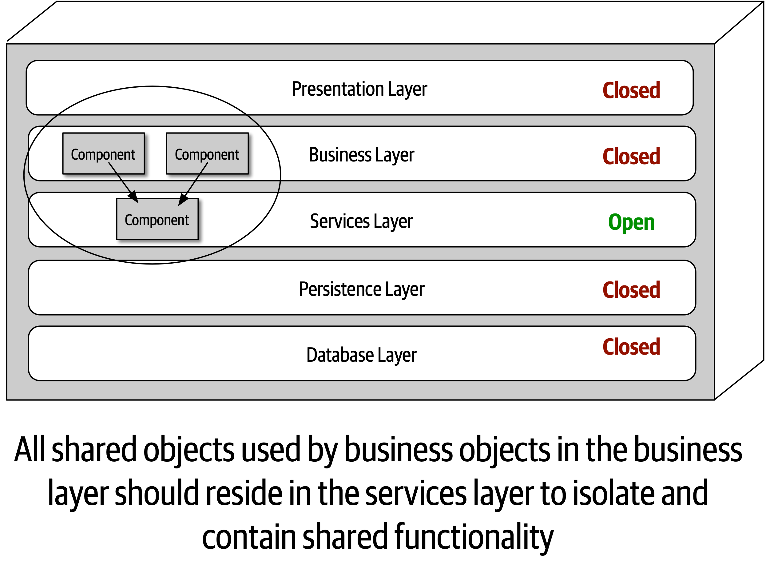
Figure 19-2. An example of an architecture decision
This architecture decision can be measured and governed automatically by using either ArchUnit in Java or NetArchTest in C#. For example, using ArchUnit in Java, the automated fitness function test might look as follows:
@Testpublicvoidshared_services_should_reside_in_services_layer(){classes().that().areAnnotatedWith(SharedService.class).should().resideInAPackage("..services..").because("All shared services classes used by business "+"objects in the business layer should reside in the services "+"layer to isolate and contain shared logic").check(myClasses);}
Notice that this automated fitness function would require new stories to be written to create a new Java annotation (@SharedService) and to then add this annotation to all shared classes. This section also specifies what the test is, where the test can be found, and how the test will be executed and when.
Notes
Another section that is not part of a standard ADR but that we highly recommend adding is the Notes section.
-
Original author
-
Approval date
-
Approved by
-
Superseded date
-
Last modified date
-
Modified by
-
Last modification
Even when storing ADRs in a version control system (such as Git), additional meta-information is useful beyond what the repository can support, so we recommend adding this section regardless of how and where ADRs are stored.
Storing ADRs
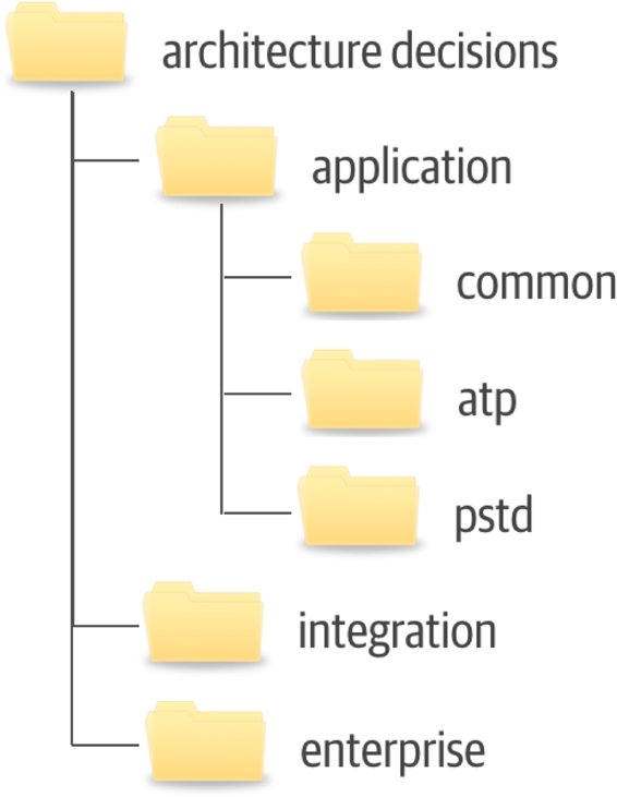
Figure 19-3. Example directory structure for storing ADRs
The application directory contains those architecture decisions that are specific to some sort of application context. This directory is subdivided into further directories. The common subdirectory is for architecture decisions that apply to all applications, such as “All framework-related classes will contain an annotation (@Framework in Java) or attribute ([Framework] in C#) identifying the class as belonging to the underlying framework code.” Subdirectories under the application directory correspond to the specific application or system context and contain the architecture decisions specific to that application or system (in this example, the ATP and PSTD applications). The integration directory contains those ADRs that involve the communication between application, systems, or services. Enterprise architecture ADRs are contained within the enterprise directory, indicating that these are global architecture decisions impacting all systems and applications. An example of an enterprise architecture ADR would be “All access to a system database will only be from the owning system,” thus preventing the sharing of databases across multiple systems.
When storing ADRs in a wiki (our recommendation), the same structure previously described applies, with each directory structure representing a navigational landing page. Each ADR would be represented as a single wiki page within each navigational landing page (Application, Integration, or Enterprise).
The directory or landing page names indicated in this section are only a recommendation. Each company can choose whatever names fit their situation, as long as those names are consistent across teams.
ADRs as Documentation
Architecture Decision Records can be used an an effective means to document a software architecture. The Context section of an ADR provides an excellent opportunity to describe the specific area of the system that requires an architecture decision to be made. This section also provides an opportunity to describe the alternatives. Perhaps more important is that the Decision section describes the reasons why a particular decision is made, which is by far the best form of architecture documentation. The Consequences section adds the final piece to the architecture documentation by describing additional aspects of a particular decision, such as the trade-off analysis of choosing performance over scalability.
Using ADRs for Standards
Very few people like standards.
Example
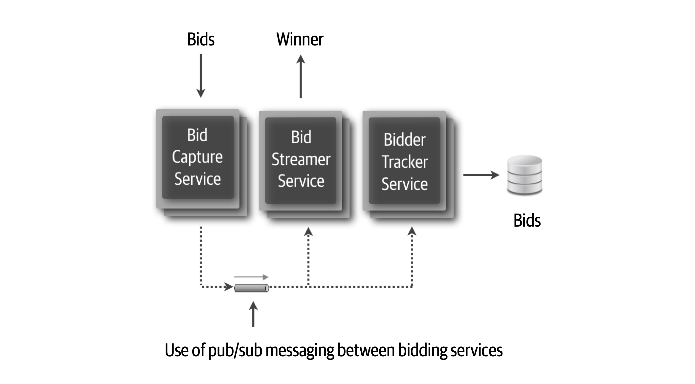
Figure 19-4. Use of pub/sub between services
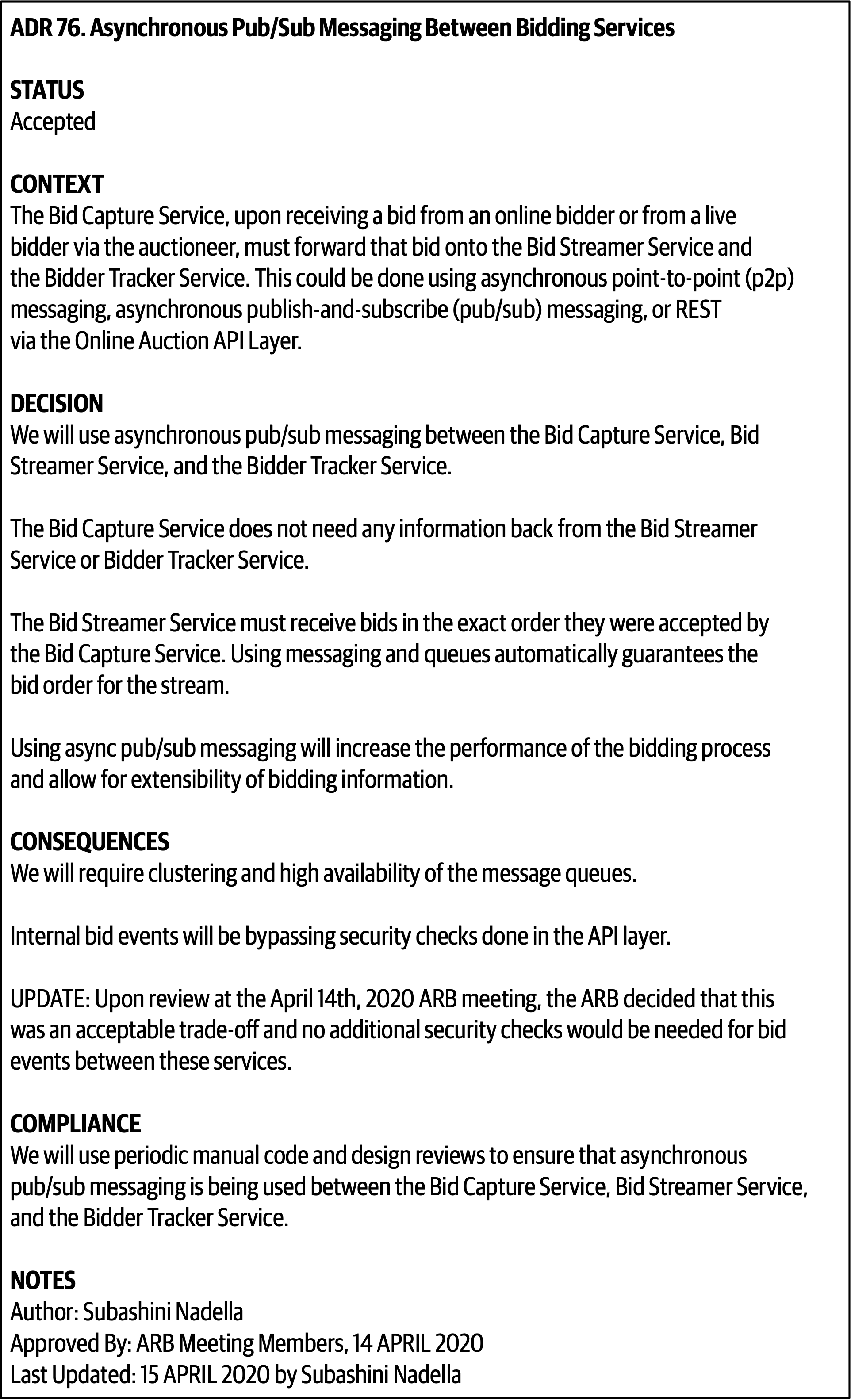
Figure 19-5. ADR 76. Asynchronous Pub/Sub Messaging Between Bidding Services
Chapter 20. Analyzing Architecture Risk
Every architecture has risk associated with it, whether it be risk involving availability, scalability, or data integrity.
Risk Matrix
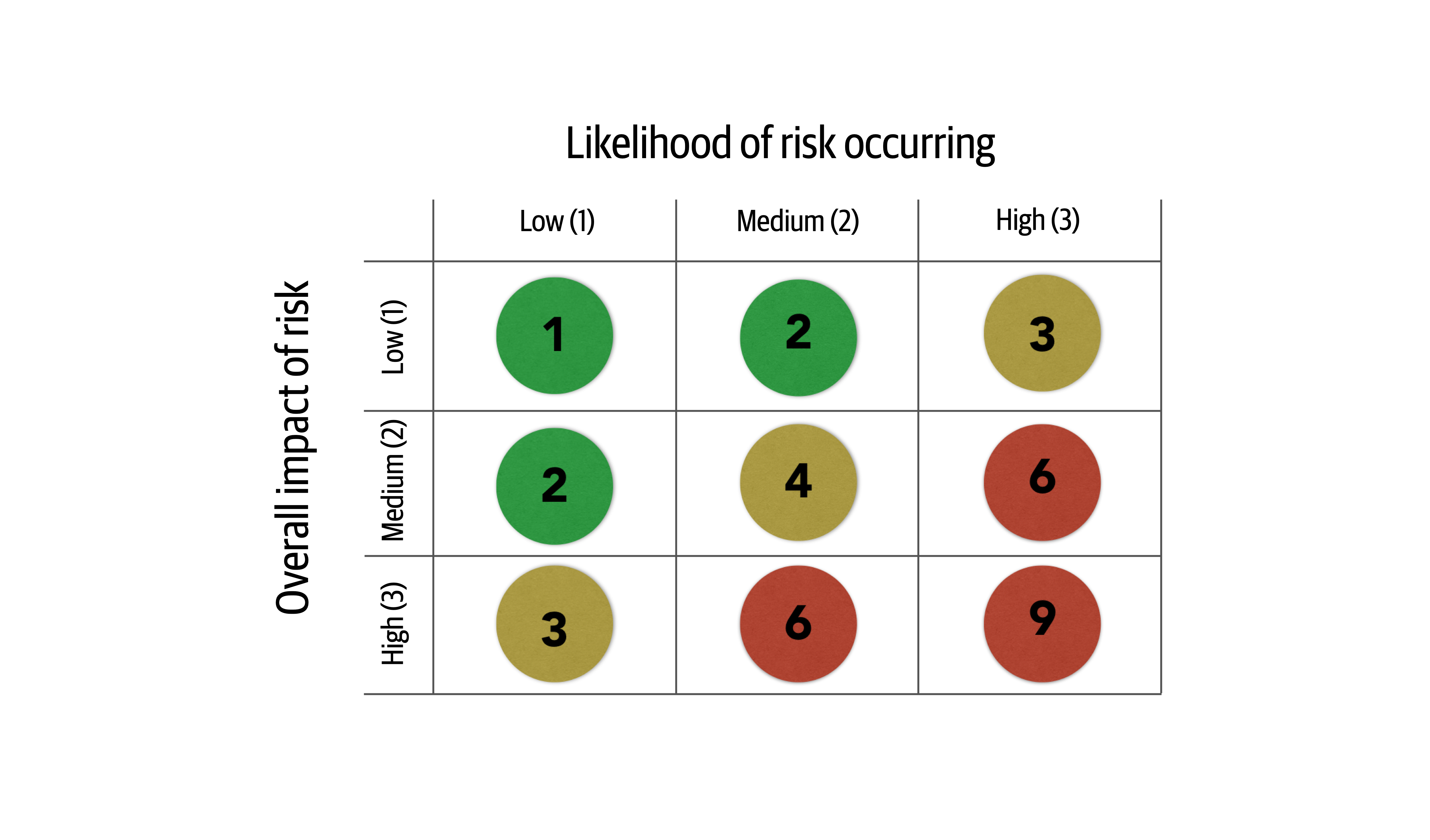
Figure 20-1. Matrix for determining architecture risk
To see how the risk matrix can be used, suppose there is a concern about availability with regard to a primary central database used in the application. First, consider the impact dimension—what is the overall impact if the database goes down or becomes unavailable? Here, an architect might deem that high risk, making that risk either a 3 (medium), 6 (high), or 9 (high). However, after applying the second dimension (likelihood of risk occurring), the architect realizes that the database is on highly available servers in a clustered configuration, so the likelihood is low that the database would become unavailable. Therefore, the intersection between the high impact and low likelihood gives an overall risk rating of 3 (medium risk).
Tip
When leveraging the risk matrix to qualify the risk, consider the impact dimension first and the likelihood dimension second.
Risk Assessments
The risk matrix described in the previous section can be used to build what is called a risk assessment.
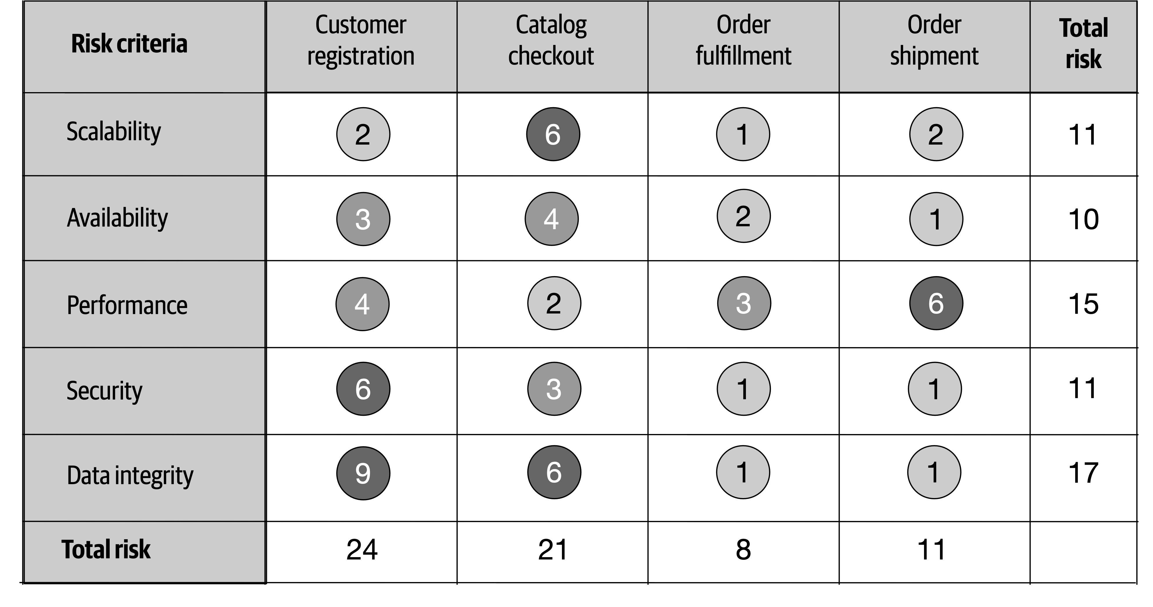
Figure 20-2. Example of a standard risk assessment
The quantified risk from the risk matrix can be accumulated by the risk criteria and also by the service or domain area. For example, notice in Figure 20-2 that the accumulated risk for data integrity is the highest risk area at a total of 17, whereas the accumulated risk for Availability is only 10 (the least amount of risk). The relative risk of each domain area can also be determined by the example risk assessment. Here, customer registration carries the highest area of risk, whereas order fulfillment carries the lowest risk. These relative numbers can then be tracked to demonstrate either improvements or degradation of risk within a particular risk category or domain area.
Although the risk assessment example in Figure 20-2 contains all the risk analysis results, rarely is it presented as such. Filtering is essential for visually indicating a particular message within a given context. For example, suppose an architect is in a meeting for the purpose of presenting areas of the system that are high risk. Rather than presenting the risk assessment as illustrated in Figure 20-2, filtering can be used to only show the high risk areas (shown in Figure 20-3), improving the overall signal-to-noise ratio and presenting a clear picture of the state of the system (good or bad).
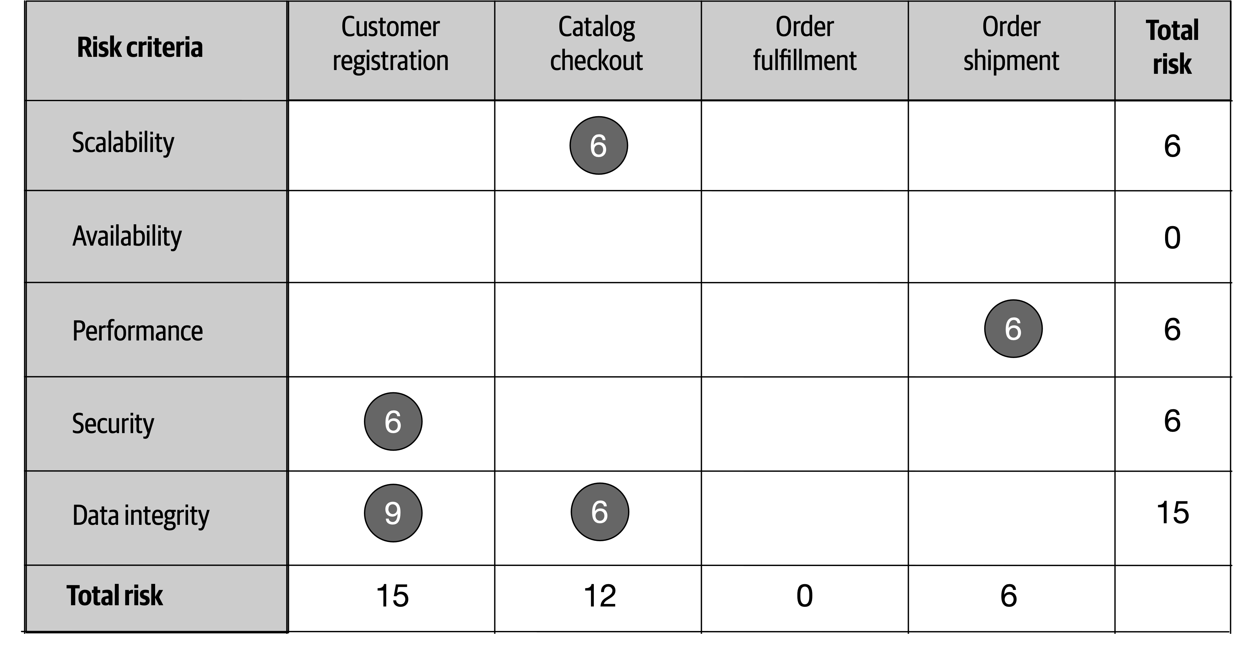
Figure 20-3. Filtering the risk assessment to only high risk
Another issue with Figure 20-2 is that this assessment report only shows a snapshot in time; it does not show whether things are improving or getting worse. In other words, Figure 20-2 does not show the direction of risk.
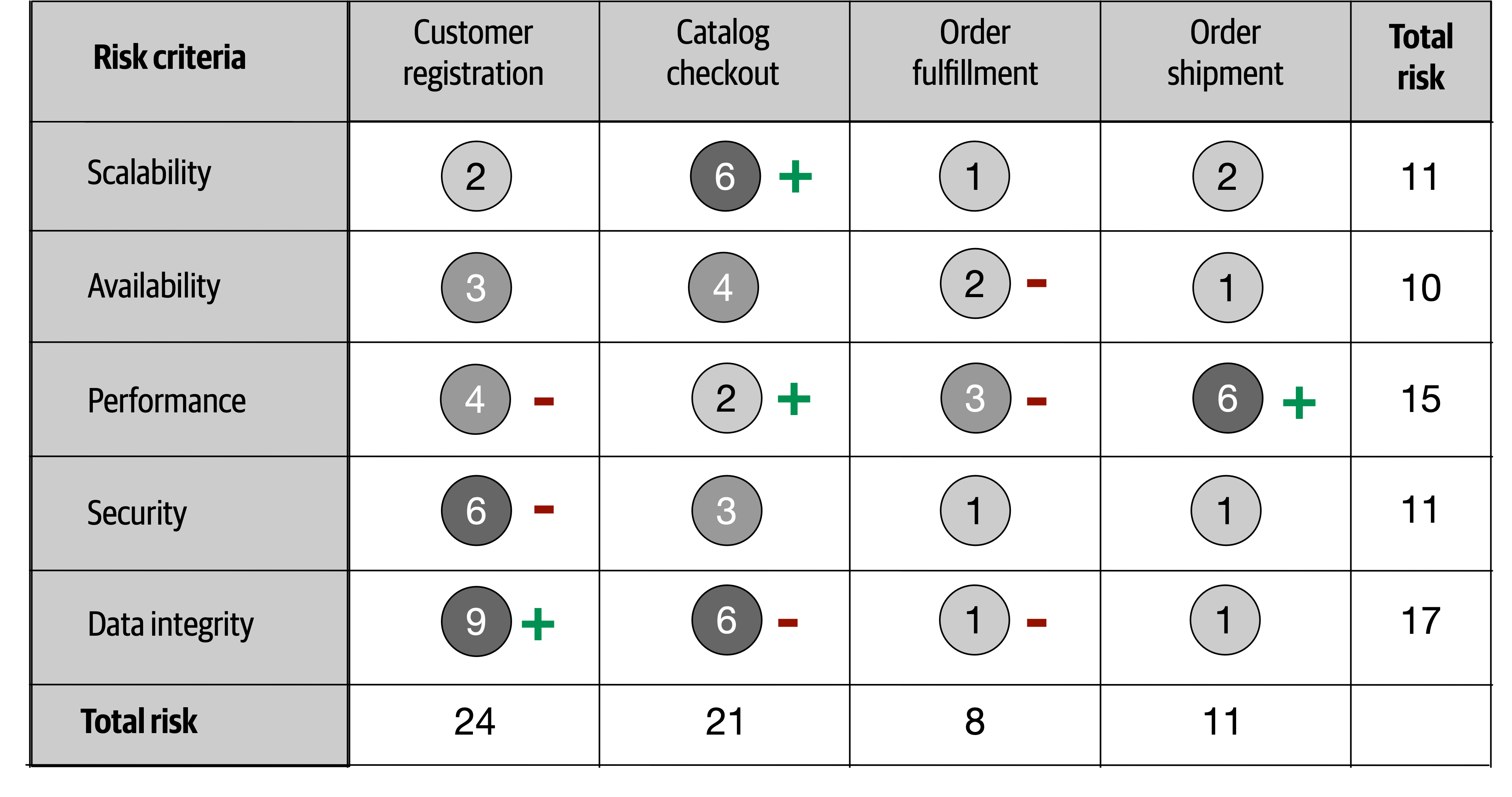
Figure 20-4. Showing direction of risk with plus and minus signs
Occasionally, even the plus and minus signs can be confusing to some people. Another technique for indicating direction is to leverage an arrow along with the risk rating number it is trending toward. This technique, as illustrated in Figure 20-5, does not require a key because the direction is clear.
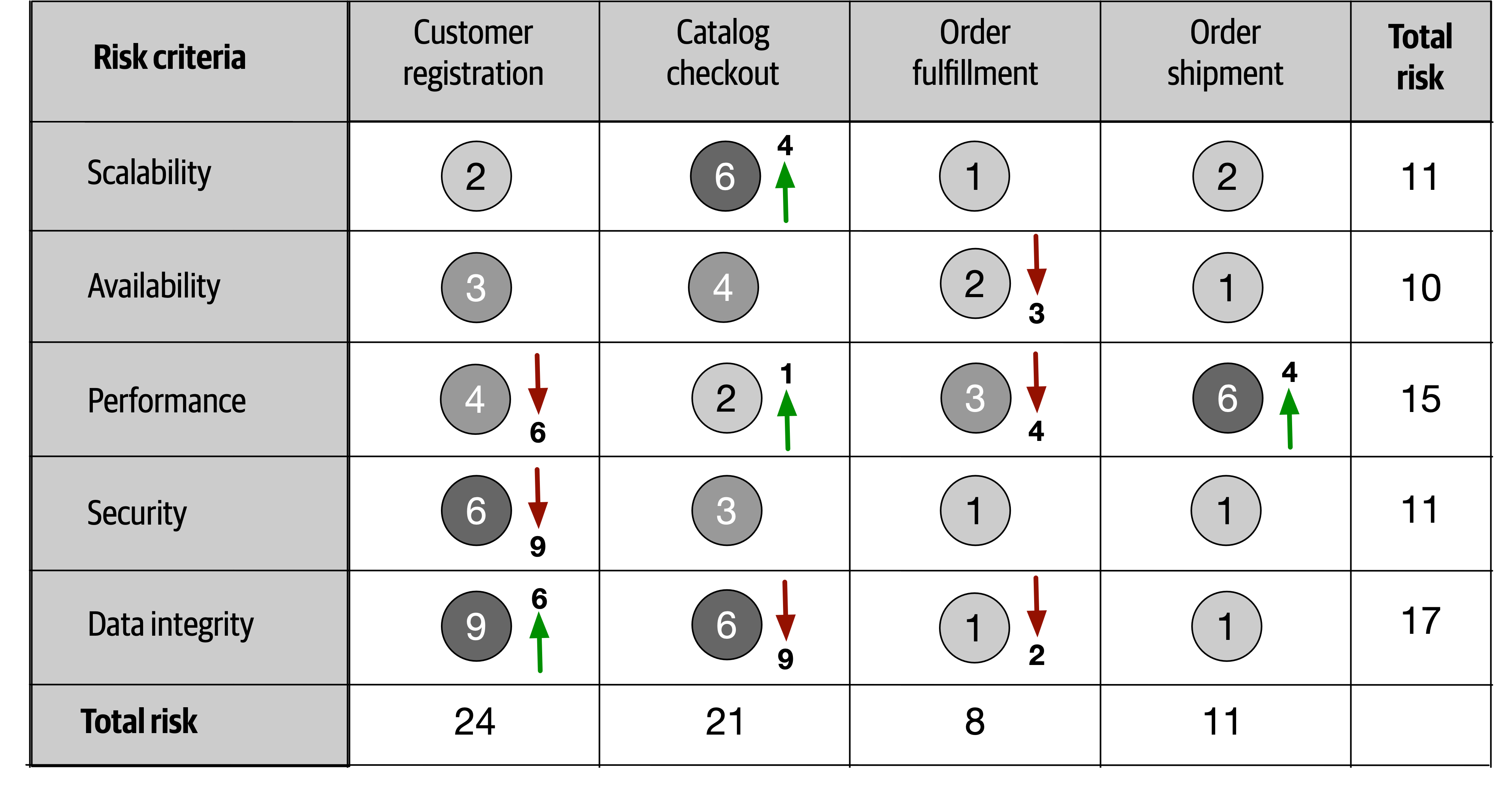
Figure 20-5. Showing direction of risk with arrows and numbers
The direction of risk can be determined by using continuous measurements through fitness functions described earlier in the book. By objectively analyzing each risk criteria, trends can be observed, providing the direction of each risk criteria.
Risk Storming
Risk storming is a collaborative exercise used to determine architectural risk within a specific dimension. Common dimensions (areas of risk) include unproven technology, performance, scalability, availability (including transitive dependencies), data loss, single points of failure, and security. While most risk storming efforts involve multiple architects, it is wise to include senior developers and tech leads as well. Not only will they provide an implementation perspective to the architectural risk, but involving developers helps them gain a better understanding of the architecture.
The risk storming effort involves both an individual part and a collaborative part. In the individual part, all participants individually (without collaboration) assign risk to areas of the architecture using the risk matrix described in the previous section. This noncollaborative part of risk storming is essential so that participants don’t influence or direct attention away from particular areas of the architecture. In the collaborative part of risk storming, all participants work together to gain consensus on risk areas, discuss risk, and form solutions for mitigating the risk.
An architecture diagram is used for both parts of the risk storming effort. For holistic risk assessments, usually a comprehensive architecture diagram is used, whereas risk storming within specific areas of the application would use a contextual architecture diagram. It is the responsibility of the architect conducting the risk storming effort to make sure these diagrams are up to date and available to all participants.
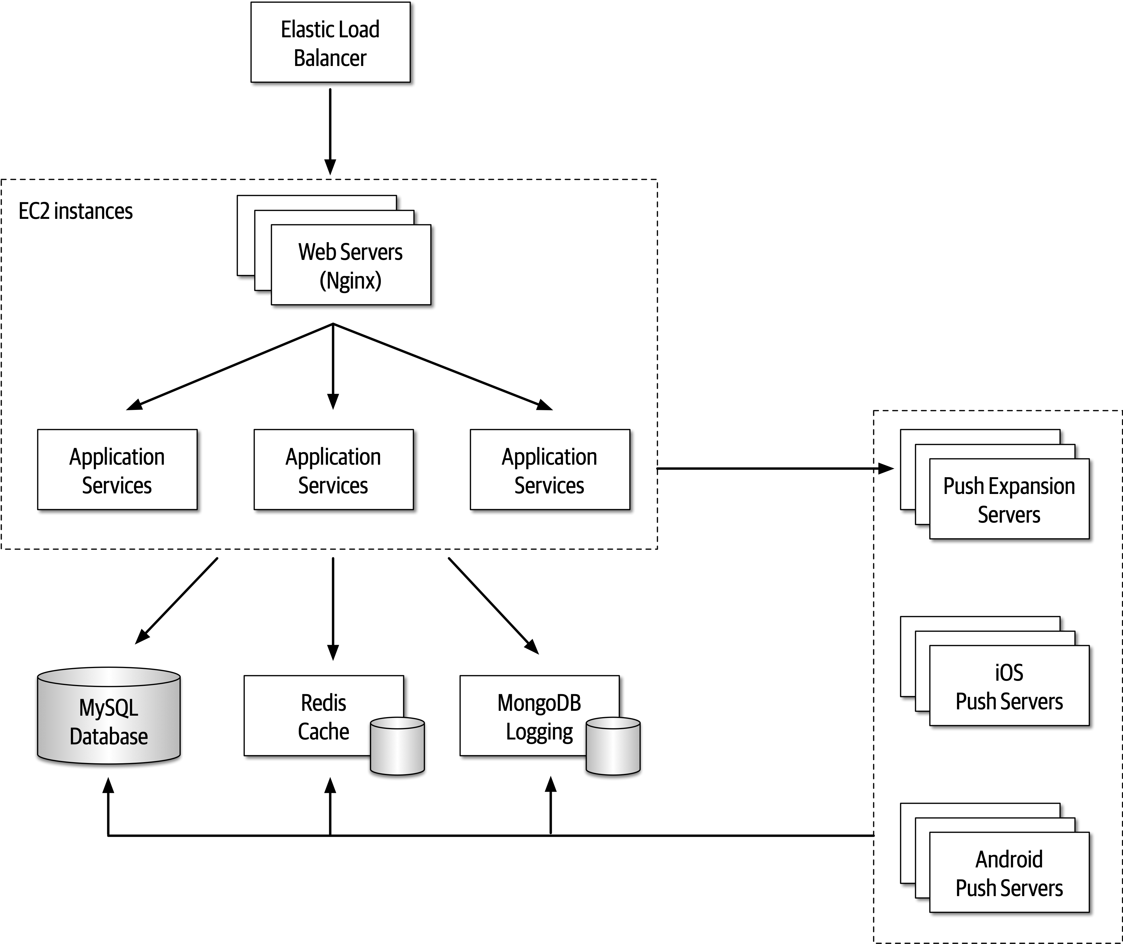
Figure 20-6. Architecture diagram for risk storming example
-
Identification
-
Consensus
-
Mitigation
Identification is always an individual, noncollaborative activity, whereas consensus and mitigation are always collaborative and involve all participants working together in the same room (at least virtually). Each of these primary activities is discussed in detail in the following sections.
Identification
-
The architect conducting the risk storming sends out an invitation to all participants one to two days prior to the collaborative part of the effort. The invitation contains the architecture diagram (or the location of where to find it), the risk storming dimension (area of risk being analyzed for that particular risk storming effort), the date when the collaborative part of risk storming will take place, and the location.
-
Using the risk matrix described in the first section of this chapter, participants individually analyze the architecture and classify the risk as low (1-2), medium (3-4), or high (6-9).
-
Participants prepare small Post-it notes with corresponding colors (green, yellow, and red) and write down the corresponding risk number (found on the risk matrix).
Most risk storming efforts only involve analyzing one particular dimension (such as performance), but there might be times, due to the availability of staff or timing issues, when multiple dimensions are analyzed within a single risk storming effort (such as performance, scalability, and data loss). When multiple dimensions are analyzed within a single risk storming effort, the participants write the dimension next to the risk number on the Post-it notes so that everyone is aware of the specific dimension. For example, suppose three participants found risk within the central database. All three identified the risk as high (6), but one participant found risk with respect to availability, whereas two participants found risk with respect to performance. These two dimensions would be discussed separately.
Tip
Whenever possible, restrict risk storming efforts to a single dimension. This allows participants to focus their attention to that specific dimension and avoids confusion about multiple risk areas being identified for the same area of the architecture.
Consensus
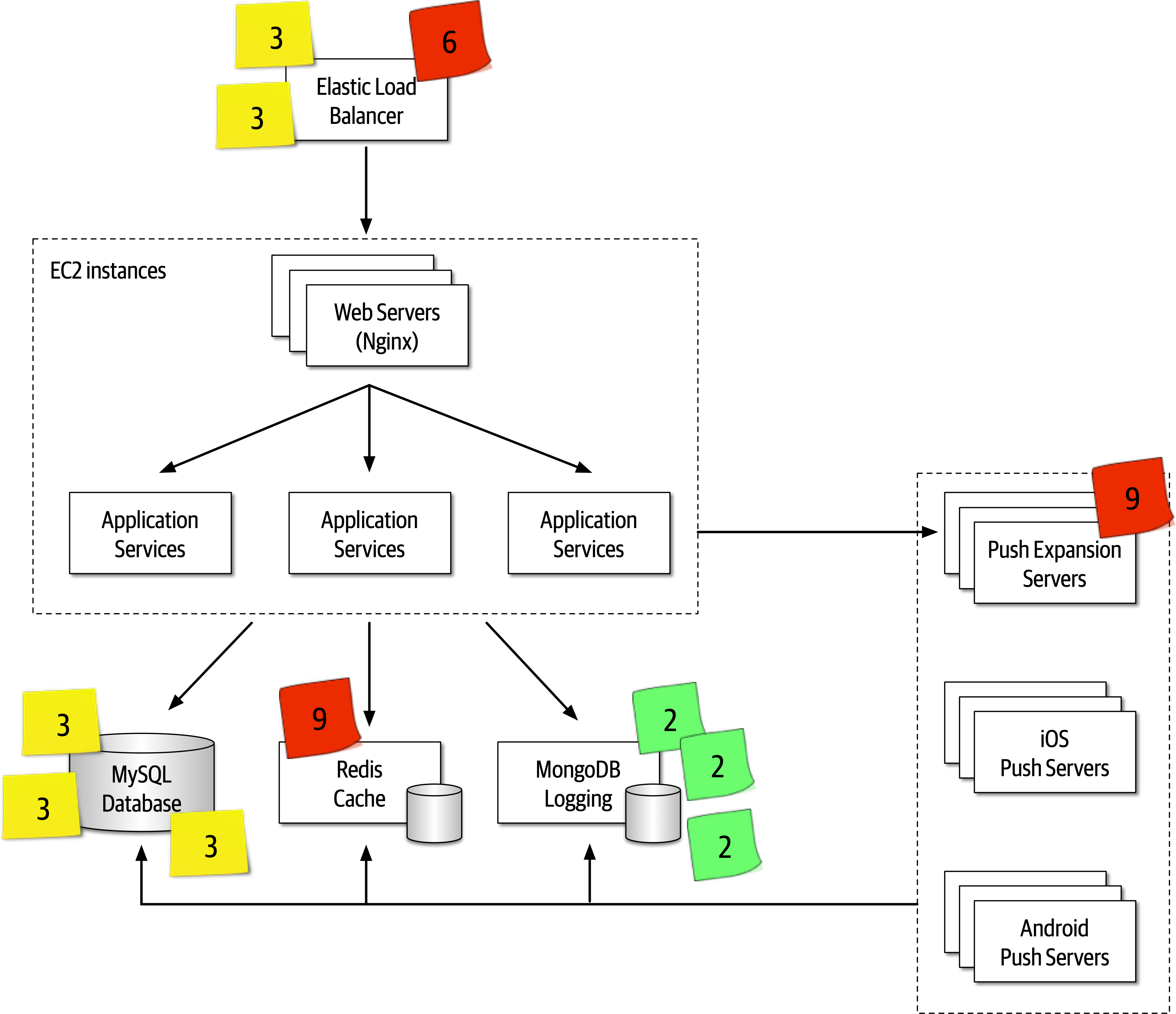
Figure 20-7. Initial identification of risk areas
Once all of the Post-it notes are in place, the collaborative part of risk storming can begin. The goal of this activity of risk storming is to analyze the risk areas as a team and gain consensus in terms of the risk qualification. Notice several areas of risk were identified in the architecture, illustrated in Figure 20-7:
-
Two participants individually identified the Elastic Load Balancer as medium risk (3), whereas one participant identified it as high risk (6).
-
One participant individually identified the Push Expansion Servers as high risk (9).
-
Three participants individually identified the MySQL database as medium risk (3).
-
One participant individually identified the Redis cache as high risk (9).
-
Three participants identified MongoDB logging as low risk (2).
-
All other areas of the architecture were not deemed to carry any risk, hence there are no Post-it notes on any other areas of the architecture.
Items 3 and 5 in the prior list do not need further discussion in this activity since all participants agreed on the level and qualification of risk. However, notice there was a difference of opinion in item 1 in the list, and items 2 and 4 only had a single participant identifying the risk. These items need to be discussed during this activity.
Item 1 in the list showed that two participants individually identified the Elastic Load Balancer as medium risk (3), whereas one participant identified it as high risk (6). In this case the other two participants ask the third participant why they identified the risk as high. Suppose the third participant says that they assigned the risk as high because if the Elastic Load Balancer goes down, the entire system cannot be accessed. While this is true and in fact does bring the overall impact rating to high, the other two participants convince the third participant that there is low risk of this happening. After much discussion, the third participant agrees, bringing that risk level down to a medium (3). However, the first and second participants might not have seen a particular aspect of risk in the Elastic Load Balancer that the third did, hence the need for collaboration within this activity of risk storming.
Case in point, consider item 2 in the prior list where one participant individually identified the Push Expansion Servers as high risk (9), whereas no other participant identified them as any risk at all. In this case, all other participants ask the participant who identified the risk why they rated it as high. That participant then says that they have had bad experiences with the Push Expansion Servers continually going down under high load, something this particular architecture has. This example shows the value of risk storming—without that participant’s involvement, no one would have seen the high risk (until well into production of course!).
Item 4 in the list is an interesting case. One participant identified the Redis cache as high risk (9), whereas no other participant saw that cache as any risk in the architecture. The other participants ask what the rationale is for the high risk in that area, and the one participant responds with, “What is a Redis cache?” In this case, Redis was unknown to the participant, hence the high risk in that area.
Tip
For unproven or unknown technologies, always assign the highest risk rating (9) since the risk matrix cannot be used for this dimension.
The example of item 4 in the list illustrates why it is wise (and important) to bring developers into risk storming sessions. Not only can developers learn more about the architecture, but the fact that one participant (who was in this case a developer on the team) didn’t know a given technology provides the architect with valuable information regarding overall risk.
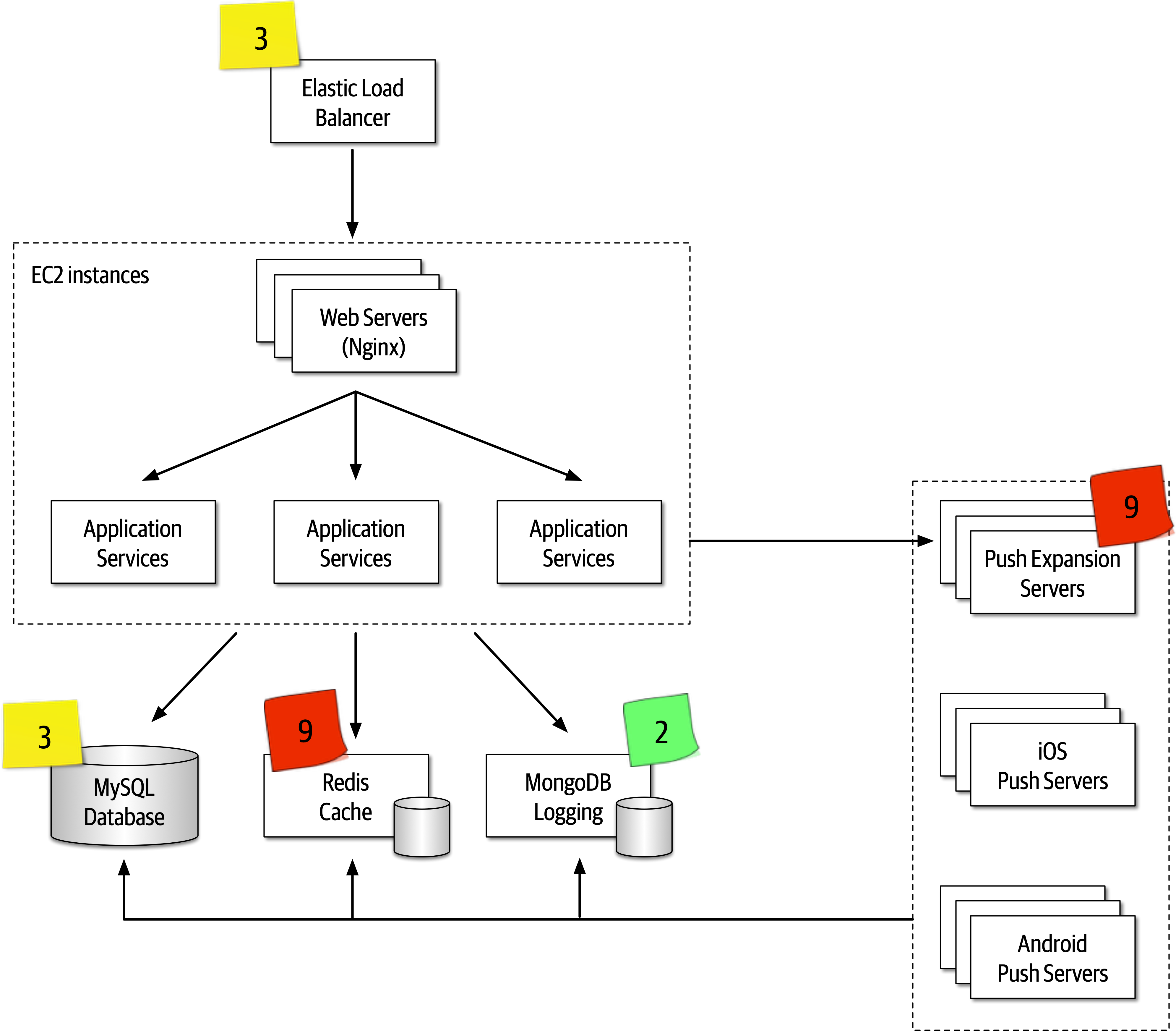
Figure 20-8. Consensus of risk areas
Mitigation
Once all participants agree on the qualification of the risk areas of the architecture, the final and most important activity occurs—risk mitigation.
This activity, which is also usually collaborative, seeks ways to reduce or eliminate the risk identified in the first activity. There may be cases where the original architecture needs to be completely changed based on the identification of risk, whereas others might be a straightforward architecture refactoring, such as adding a queue for back pressure to reduce a throughput bottleneck issue.
Agile Story Risk Analysis
Risk Storming Examples
-
The system will use a third-party diagnostics engine that serves up questions and guides the nurses or patients regarding their medical issues.
-
Patients can either call in using the call center to speak to a nurse or choose to use a self-service website that accesses the diagnostic engine directly, bypassing the nurses.
-
The system must support 250 concurrent nurses nationwide and up to hundreds of thousands of concurrent self-service patients nationwide.
-
Nurses can access patients’ medical records through a medical records exchange, but patients cannot access their own medical records.
-
The system must be HIPAA compliant with regard to the medical records. This means that it is essential that no one but nurses have access to medical records.
-
Outbreaks and high volume during cold and flu season need to be addressed in the system.
-
Call routing to nurses is based on the nurse’s profile (such as bilingual needs).
-
The third-party diagnostic engine can handle about 500 requests a second.
There are four main services in this system: a case management service, a nurse profile management service, an interface to the medical records exchange, and the external third-party diagnostics engine. All communications are using REST with the exception of proprietary protocols to the external systems and call center services.
The architect has reviewed this architecture numerous times and believes it is ready for implementation. As a self-assessment, study the requirements and the architecture diagram in Figure 20-9 and try to determine the level of risk within this architecture in terms of availability, elasticity, and security. After determining the level of risk, then determine what changes would be needed in the architecture to mitigate that risk. The sections that follow contain scenarios that can be used as a comparison.
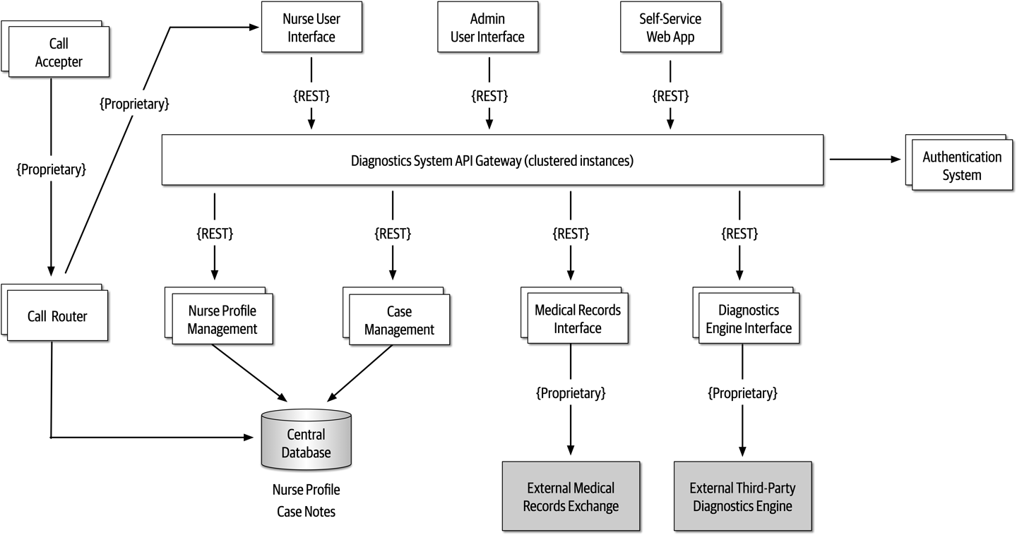
Figure 20-9. High-level architecture for nurse diagnostics system example
Availability
During the first risk storming exercise, the architect chose to focus on availability first since system availability is critical for the success of this system.
-
The use of a central database was identified as high risk (6) due to high impact (3) and medium likelihood (2).
-
The diagnostics engine availability was identified as high risk (9) due to high impact (3) and unknown likelihood (3).
-
The medical records exchange availability was identified as low risk (2) since it is not a required component for the system to run.
-
Other parts of the system were not deemed as risk for availability due to multiple instances of each service and clustering of the API gateway.
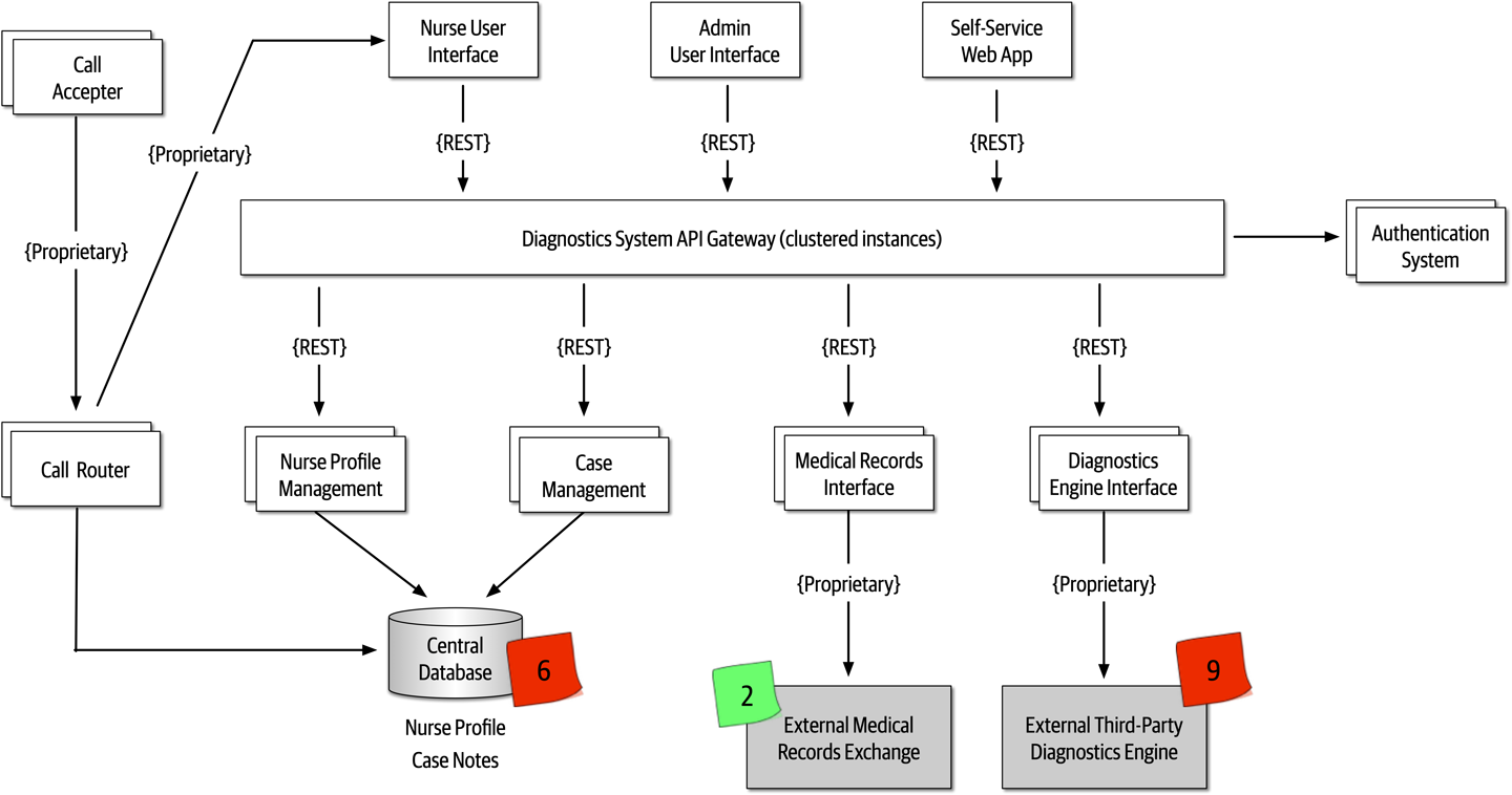
Figure 20-10. Availability risk areas
During the risk storming effort, all participants agreed that while nurses can manually write down case notes if the database went down, the call router could not function if the database were not available. To mitigate the database risk, participants chose to break apart the single physical database into two separate databases: one clustered database containing the nurse profile information, and one single instance database for the case notes. Not only did this architecture change address the concerns about availability of the database, but it also helped secure the case notes from admin access. Another option to mitigate this risk would have been to cache the nurse profile information in the call router. However, because the implementation of the call router was unknown and may be a third-party product, the participants went with the database approach.
Mitigating the risk of availability of the external systems (diagnostics engine and medical records exchange) is much harder to manage due to the lack of control of these systems.
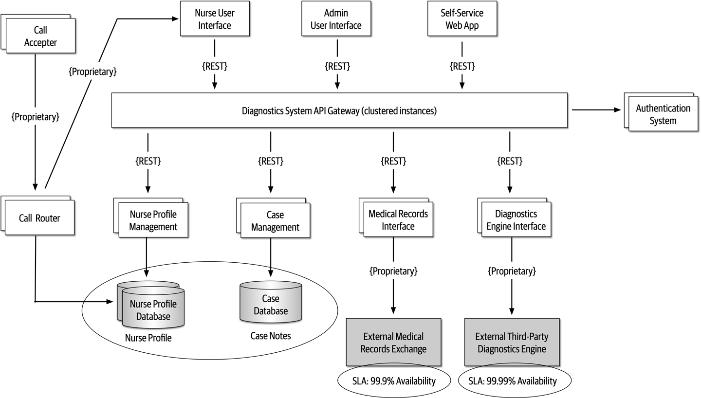
Figure 20-11. Architecture modifications to address availability risk
Elasticity
On the second risk storming exercise, the architect chose to focus on elasticity—spikes
During the risk storming session, the participants all identified the diagnostics engine interface as high risk (9). With only 500 requests per second, the participants calculated that there was no way the diagnostics engine interface could keep up with the anticipated throughput, particularly with the current architecture utilizing REST as the interface protocol.
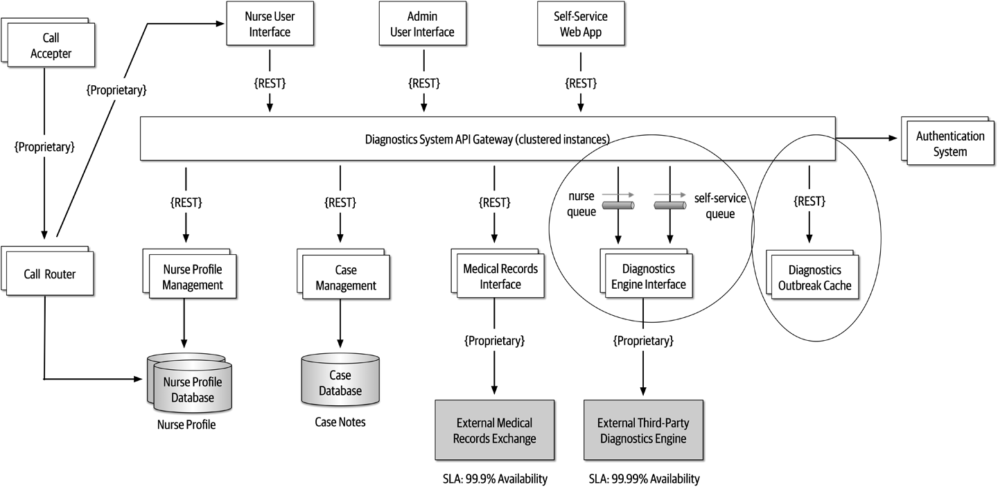
Figure 20-12. Architecture modifications to address elasticity risk
Security
Encouraged by the results and success of the first two risk storming efforts, the architect
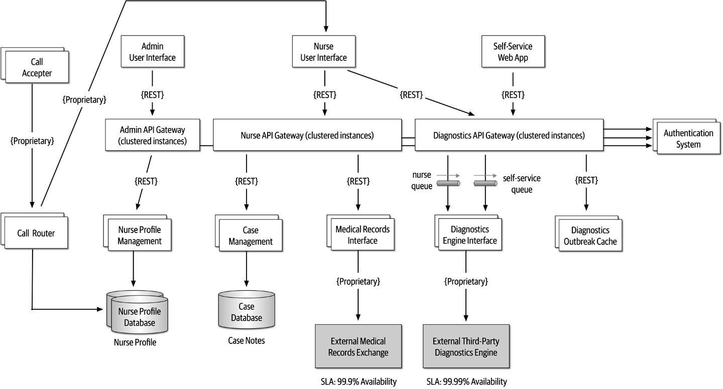
Figure 20-13. Final architecture modifications to address security risk
The prior scenario illustrates the power of risk storming. By collaborating with other architects, developers, and key stakeholders on dimensions of risk that are vital to the success of the system, risk areas are identified that would otherwise have gone unnoticed. Compare figures Figure 20-9 and Figure 20-13 and notice the significant difference in the architecture prior to risk storming and then after risk storming. Those significant changes address availability concerns, elasticity concerns, and security concerns within the architecture.
Risk storming is not a one-time process. Rather, it is a continuous process through the life of any system to catch and mitigate risk areas before they happen in production. How often the risk storming effort happens depends on many factors, including frequency of change, architecture refactoring efforts, and the incremental development of the architecture. It is typical to undergo a risk storming effort on some particular dimension after a major feature is added or at the end of every iteration.
Chapter 21. Diagramming and Presenting Architecture
Newly minted architects often comment on how surprised they are at how varied the job is outside of technical knowledge and
When visually describing an architecture, the creator often must show different views of the architecture. For example, the architect will likely show an overview of the entire architecture topology, then drill into individual parts to delve into design details. However, if the architect shows a portion without indicating where it lies within the overall architecture, it confuses viewers. Representational consistency is the practice of always showing the relationship between parts of an architecture, either in diagrams or presentations, before changing views.
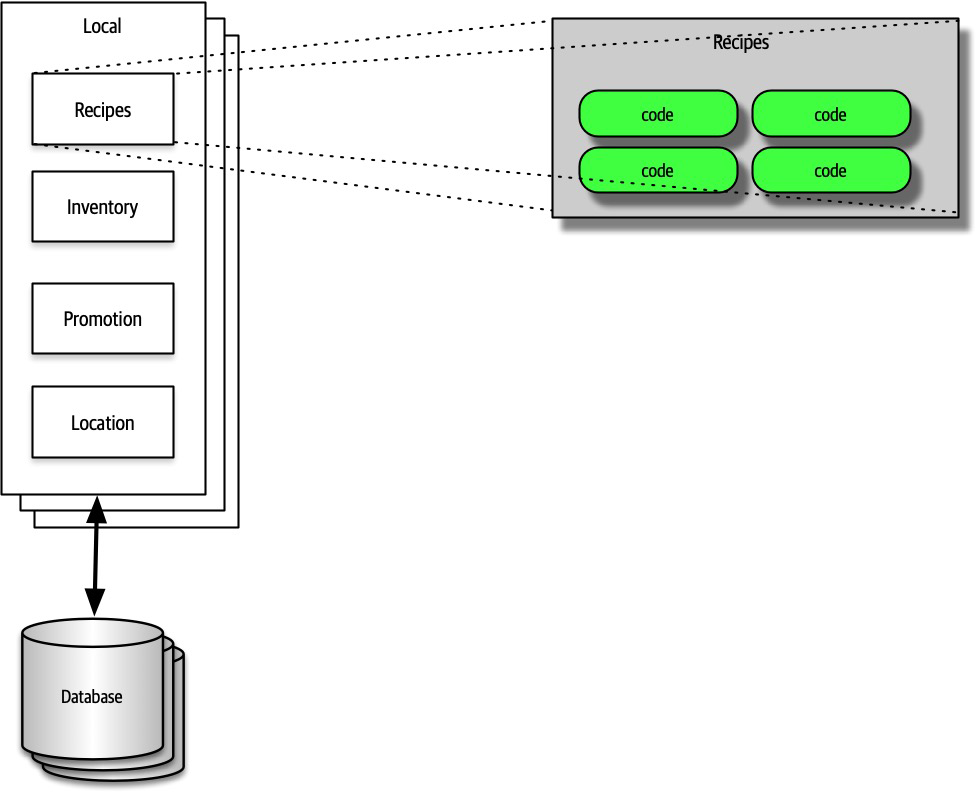
Figure 21-1. Using representational consistency to indicate context in a larger diagram
Careful use of representational consistency ensures that viewers understand the scope of items being presented, eliminating a common source of confusion.
Diagramming
The topology of architecture is always of interest to architects and developers because it captures how the structure fits together and forms a valuable shared understanding across the team.
Tools
An architect’s favorite variation on the cell phone photo of a whiteboard (along with the inevitable “Do Not Erase!” imperative) uses a tablet attached to an overhead projector rather than a whiteboard. This offers several advantages. First, the tablet has an unlimited canvas and can fit as many drawings that a team might need. Second, it allows copy/paste “what if” scenarios that obscure the original when done on a whiteboard. Third, images captured on a tablet are already digitized and don’t have the inevitable glare associated with cell phone photos of whiteboards.
Eventually, an architect needs to create nice diagrams in a fancy tool, but make sure the team has iterated on the design sufficiently to invest time in capturing something.
- Layers
- Drawing tools often support layers, which architects should learn well. A layer allows the drawer to link a group of items together logically to enable hiding/showing individual layers.Using layers, an architect can build a comprehensive diagram but hide overwhelming details when they aren’t necessary. Using layers also allows architects to incrementally build pictures for presentations later (see“Incremental Builds”).
- Stencils/templates
-
Stencils allow an architect to build up a library of common visual components, often composites of other basic shapes.
For example, throughout this book, readers have seen standard pictures of things like microservices, which exist as a single item in the authors’ stencil. Building a stencil for common patterns and artifacts within an organization creates consistency within architecture diagrams and allows the architect to build new diagrams quickly. - Magnets
- Many drawing tools offer assistance when drawing lines between shapes.Magnets represent the places on those shapes where lines snap to connect automatically, providing automatic alignment and other visual niceties. Some tools allow the architect to add more magnets or create their own to customize how the connections look within their diagrams.
In addition to these specific helpful features, the tool should, of course, support lines, colors, and other visual artifacts, as well as the ability to export in a wide variety of formats.
Diagramming Standards: UML, C4, and ArchiMate
UML
Architects and developers still use UML class and sequence diagrams to communicate structure and workflow, but most of the other UML diagram types have fallen into disuse.
C4
- Context
- Represents the entirecontext of the system, including the roles of users and external dependencies.
- Container
- The physical (and often logical) deployment boundaries and containers within the architecture.This view forms a good meeting point for operations and architects.
- Component
- The component view of the system; this most neatly aligns with an architect’s view of the system.
- Class
- C4 uses the same style of class diagrams from UML, which are effective, so there is no need to replace them.
ArchiMate
Diagram Guidelines
Titles
Lines
Generally, one of the few standards that exists in architecture diagrams is that solid lines tend to indicate synchronous communication and dotted lines indicate asynchronous communication.
Shapes
We tend to use three-dimensional boxes to indicate deployable artifacts and rectangles to indicate containership, but we don’t have any particular key beyond that.
Labels
Color
Figure 21-2. Reproduction of microservices communication example showing different services in unique colors
Keys
If shapes are ambiguous for any reason, include a key on the diagram clearly indicating what each shape represents.
Presenting
Presentation Patterns makes an important observation about the fundamental difference between creating a document versus a presentation to make a case for something—time. In a presentation, the presenter controls how quickly an idea is unfolding, whereas the reader of a document controls that. Thus, one of the most important skills an architect can learn in their presentation tool of choice is how to manipulate time.
Manipulating Time
Presentation tools offer two ways to manipulate time on slides: transitions and animations.
Incremental Builds
When presenting, the speaker has two information channels: verbal and visual. By placing too much text on the slides and then saying essentially the same words, the presenter is overloading one information channel and starving the other. The better solution to this problem is to use incremental builds for slides, building up (hopefully graphical) information as needed rather than all at once.
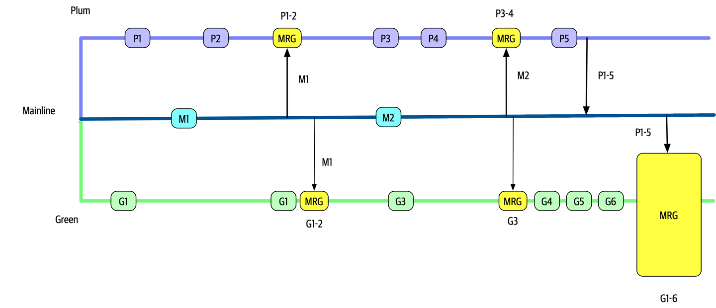
Figure 21-3. Bad version of a slide showing a negative anti-pattern
In Figure 21-3, if the presenter shows the entire slide right away, the audience can see that something bad happens toward the end, but they have to wait for the exposition to get to that point.
Instead, the architect should use the same image but obscure parts of it when showing the slide (using a borderless white box) and expose a portion at a time (by performing a build out on the covering box), as shown in Figure 21-4.
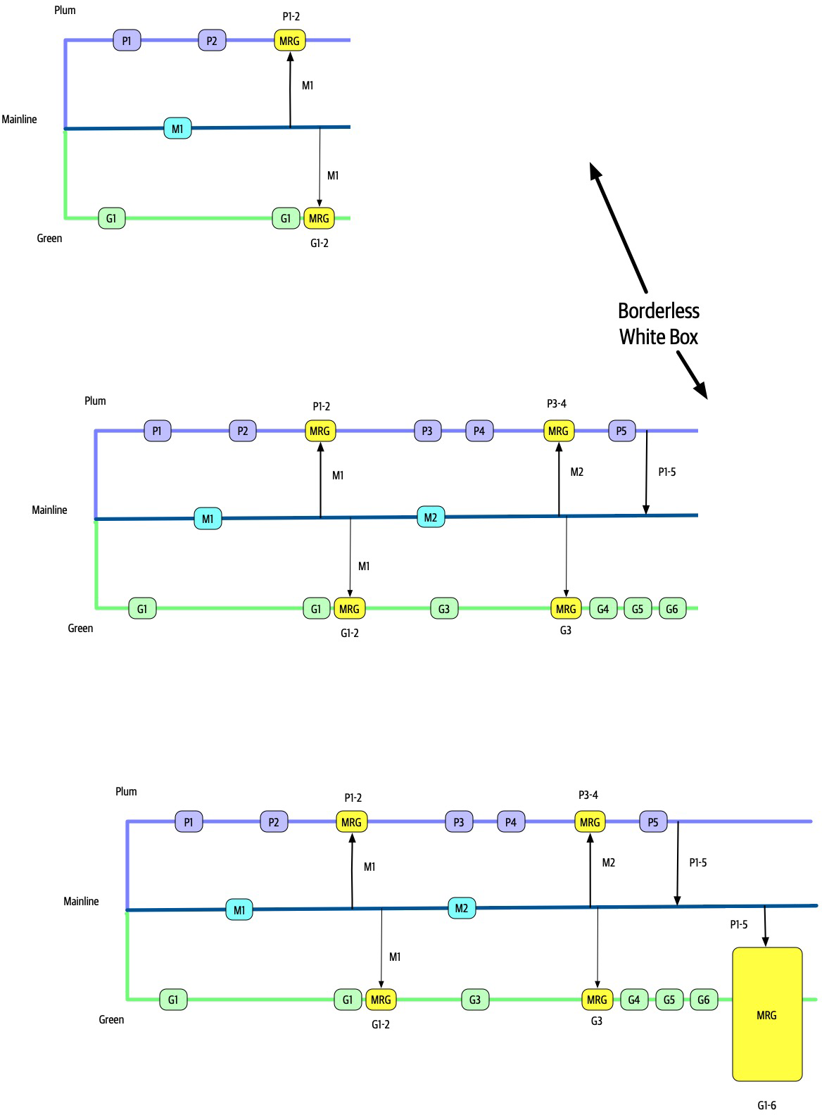
Figure 21-4. A better, incremental version that maintains suspense
In Figure 21-4, the presenter still has a fighting chance of keeping some suspense alive, making the talk inherently more interesting.
Using animations and transitions in conjunction with incremental builds allows the presenter to make more compelling, entertaining presentations.
Infodecks Versus Presentations
Some architects build slide decks in tools like PowerPoint and Keynote but never actually present them.
The difference between these two media is comprehensiveness of content and use of transitions and animations. If someone is going to flip through the deck like a magazine article, the author of the slides does not need to add any time elements. The other key difference between infodecks and presentations is the amount of material. Because infodecks are meant to be standalone, they contain all the information the creator wants to convey. When doing a presentation, the slides are (purposefully) meant to be half of the presentation, the other half being the person standing there talking!
Slides Are Half of the Story
Invisibility
Chapter 22. Making Teams Effective
In addition to creating a technical architecture and making architecture decisions, a software architect is also responsible
Team Boundaries
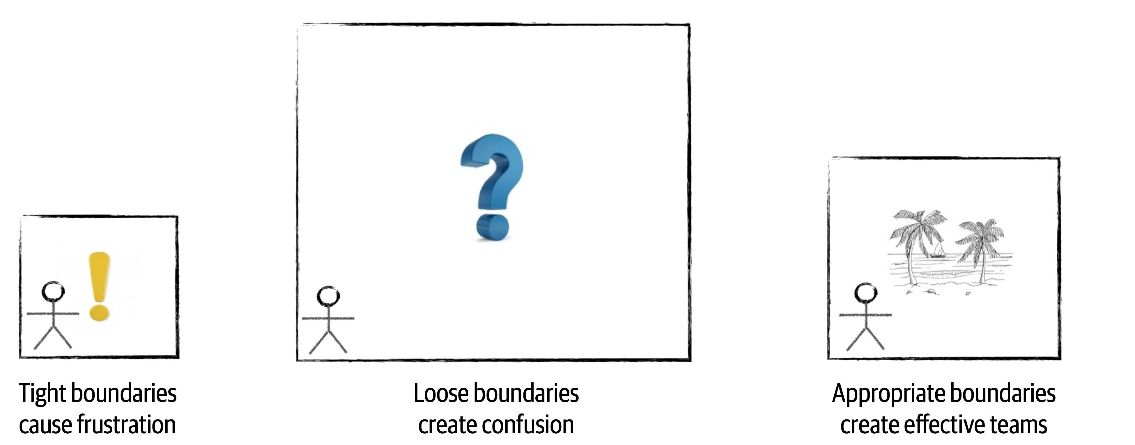
Figure 22-1. Boundary types created by a software architect
Architects that create too many constraints form a tight box around the development teams, preventing access to many of the tools, libraries, and practices that are required to implement the system effectively. This causes frustration within the team, usually resulting in developers leaving the project for happier and healthier environments.
The opposite can also happen. A software architect can create constraints that are too loose (or no constraints at all), leaving all of the important architecture decisions to the development team. In this scenario, which is just as bad as tight constraints, the team essentially takes on the role of a software architect, performing proof of concepts and battling over design decisions without the proper level of guidance, resulting in unproductiveness, confusion, and frustration.
An effective software architect strives to provide the right level of guidance and constraints so that the team has the correct tools and libraries in place to effectively implement the architecture. The rest of this chapter is devoted to how to create these effective boundaries.
Architect Personalities
Control Freak

Figure 22-2. Control freak architect (iStockPhoto)
Control freak architects produce the tight boundaries discussed in the prior section. A control freak architect might restrict the development team from downloading any useful open source or third-party libraries and instead insist that the teams write everything from scratch using the language API. Control freak architects might also place tight restrictions on naming conventions, class design, method length, and so on. They might even go so far as to write pseudocode for the development teams. Essentially, control freak architects steal the art of programming away from the developers, resulting in frustration and a lack of respect for the architect.
It is very easy to become a control freak architect, particularly when transitioning from developer to architect. An architect’s role is to create the building blocks of the application (the components) and determine the interactions between those components. The developer’s role in this effort is to then take those components and determine how they will be implemented using class diagrams and design patterns. However, in the transaction from developer to architect, it is all too tempting to want to create the class diagrams and design patterns as well since that was the newly minted architect’s prior role.
For example, suppose an architect creates a component (building block of the architecture) to manage reference data within the system. Reference data consists of static name-value pair data used on the website, as well as things like product codes and warehouse codes (static data used throughout the system). The architect’s role is to identify the component (in this case, Reference Manager), determine the core set of operations for that component (for example, GetData, SetData, ReloadCache, NotifyOnUpdate, and so on), and which components need to interact with the Reference Manager. The control freak architect might think that the best way to implement this component is through a parallel loader pattern leveraging an internal cache, with a particular data structure for that cache. While this might be an effective design, it’s not the only design. More importantly, it’s no longer the architect’s role to come up with this internal design for the Reference Manager—it’s the role of the developer.
Armchair Architect

Figure 22-3. Armchair architect (iStockPhoto)
The armchair architect is the type of architect who hasn’t coded in a very long time (if at all) and doesn’t take the
In some cases the armchair architect is simply in way over their head in terms of the technology or business domain and therefore cannot possibly lead or guide teams from a technical or business problem standpoint. For example, what do developers do? Why, they code, of course. Writing program code is really hard to fake; either a developer writes software code, or they don’t. However, what does an architect do? No one knows! Most architects draw lots of lines and boxes—but how detailed should an architect be in those diagrams? Here’s a dirty little secret about architecture—it’s really easy to fake it as an architect!
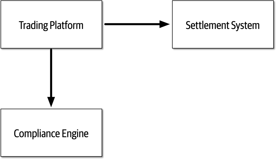
Figure 22-4. Trading system architecture created by an armchair architect
Armchair architects create loose boundaries around development teams, as discussed in the prior section. In this scenario, development teams end up taking on the role of architect, essentially doing the work an architect is supposed to be doing. Team velocity and productivity suffer as a result, and teams get confused about how the system should work.
Like the control freak architect, it is all too easy to become an armchair architect. The biggest indicator that an architect might be falling into the armchair architect personality is not having enough time to spend with the development teams implementing the architecture (or choosing not to spend time with the development teams). Development teams need an architect’s support and guidance, and they need the architect available for answering technical or business-related questions when they arise. Other indicators of an armchair architect are following:
-
Not fully understanding the business domain, business problem, or technology used
-
Not enough hands-on experience developing software
-
Not considering the implications associated with the implementation of the architecture solution
In some cases it is not the intention of an architect to become an armchair architect, but rather it just “happens” by being spread too thin between projects or development teams and loosing touch with technology or the business domain. An architect can avoid this personality by getting more involved in the technology being used on the project and understanding the business problem and business domain.
Effective Architect

Figure 22-5. Effective software architect (iStockPhoto)
An effective software architect produces
How Much Control?
Knowing how much an effective software architect should be a control freak and how much they should be an armchair architect involves five main factors. These factors also determine how many teams (or projects) a software architect can manage at once:
- Team familiarity
-
How well do the team members know each other? Have they worked together before on a project? Generally, the better team members know each other, the less control is needed because team members start to become self-organizing. Conversely, the newer the team members, the more control needed to help facilitate collaboration among team members and reduce cliques within the team.
- Team size
-
How big is the team? (We consider more than 12 developers on the same team to be a big team, and 4 or fewer to be a small team.) The larger the team, the more control is needed. The smaller the team, less control is needed. This is discussed in more detail in “Team Warning Signs”.
- Overall experience
-
How many team members are senior? How many are junior? Is it a mixed team of junior and senior developers? How well do they know the technology and business domain? Teams with lots of junior developers require more control and mentoring, whereas teams with more senior developers require less control. In the latter cases, the architect moves from the role of a mentor to that of a facilitator.
- Project complexity
-
Is the project highly complex or just a simple website? Highly complex projects require the architect to be more available to the team and to assist with issues that arise, hence more control is needed on the team. Relatively simple projects are straightforward and hence do not require much control.
- Project duration
-
Is the project short (two months), long (two years), or average duration (six months)? The shorter the duration, the less control is needed; conversely, the longer the project, the more control is needed.
While most of the factors make sense with regard to more or less control, the project duration factor may not appear to make sense. As indicated in the prior list, the shorter the project duration, the less control is needed; the longer the project duration, the more control is needed. Intuitively this might seem reversed, but that is not the case. Consider a quick two-month project. Two months is not a lot of time to qualify requirements, experiment, develop code, test every scenario, and release into production. In this case the architect should act more as an armchair architect, as the development team already has a keen sense of urgency. A control freak architect would just get in the way and likely delay the project. Conversely, think of a project duration of two years. In this scenario the developers are relaxed, not thinking in terms of urgency, and likely planning vacations and taking long lunches. More control is needed by the architect to ensure the project moves along in a timely fashion and that complex tasks are accomplished first.
It is typical within most projects that these factors are utilized to determine the level of control at the start of a project; but as the system continues to evolve, the level of control changes. Therefore, we advise that these factors continually be analyzed throughout the life cycle of a project to determine how much control to exert on the development team.
To illustrate how each of these factors can be used to determine the level of control an architect should have on a team, assume a fixed scale of 20 points for each factor. Minus values point more toward being an armchair architect (less control and involvement), whereas plus values point more toward being a control freak architect (more control and involvement). This scale is illustrated in Figure 22-6.
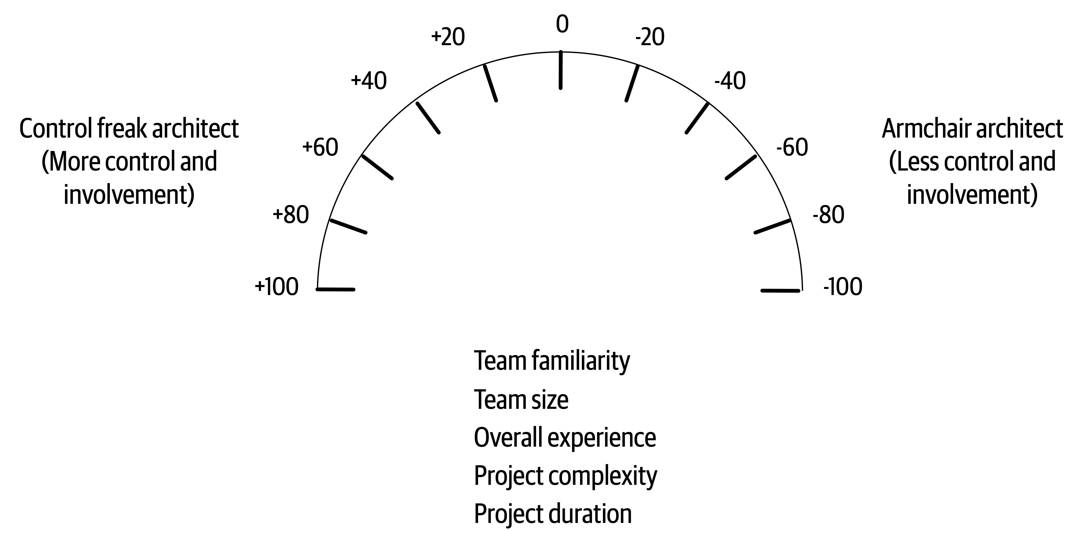
Figure 22-6. Scale for the amount of control
Applying this sort of scaling is not exact, of course, but it does help in determining the relative control to exert on a team. For example, consider the project scenario shown in Table 22-1 and Figure 22-7. As shown in the table, the factors point to either a control freak (+20) or an armchair architect (-20). These factors add up and to an accumulated score of -60, indicating that the architect should play more of an armchair architect role and not get in the team’s way.
| Factor | Value | Rating | Personality |
|---|---|---|---|
Team familiarity | New team members | +20 | Control freak |
Team size | Small (4 members) | -20 | Armchair architect |
Overall experience | All experienced | -20 | Armchair architect |
Project complexity | Relatively simple | -20 | Armchair architect |
Project duration | 2 months | -20 | Armchair architect |
Accumulated score | -60 | Armchair architect |
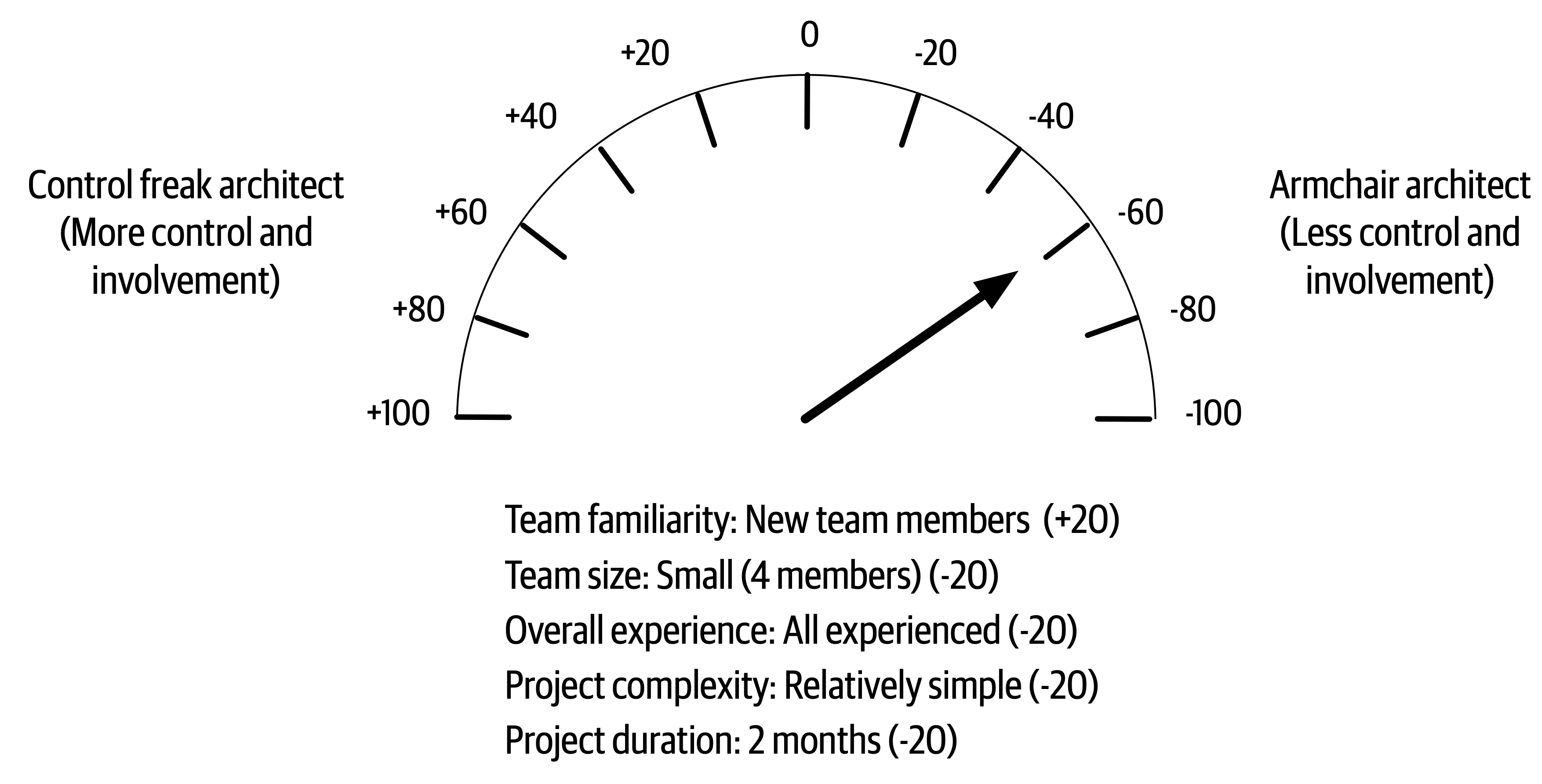
Figure 22-7. Amount of control for scenario 1
In scenario 1, these factors are all taken into account to demonstrate that an effective software architect should initially play the role of facilitator and not get too involved in the day-to-day interactions with the team. The architect will be needed for answering questions and to make sure the team is on track, but for the most part the architect should be largely hands-off and let the experienced team do what they know best—develop software quickly.
Consider another type of scenario described in Table 22-2 and illustrated in Figure 22-8, where the team members know each other well, but the team is large (12 team members) and consists mostly of junior (inexperienced) developers. The project is relatively complex with a duration of six months. In this case, the accumulated score comes out to -20, indicating that the effective architect should be involved in the day-to-day activities within the team and take on a mentoring and coaching role, but not so much as to disrupt the team.
| Factor | Value | Rating | Personality |
|---|---|---|---|
Team familiarity | Know each other well | -20 | Armchair architect |
Team size | Large (12 members) | +20 | Control freak |
Overall experience | Mostly junior | +20 | Control freak |
Project complexity | High complexity | +20 | Control freak |
Project duration | 6 months | -20 | Armchair architect |
Accumulated score | -20 | Control freak |
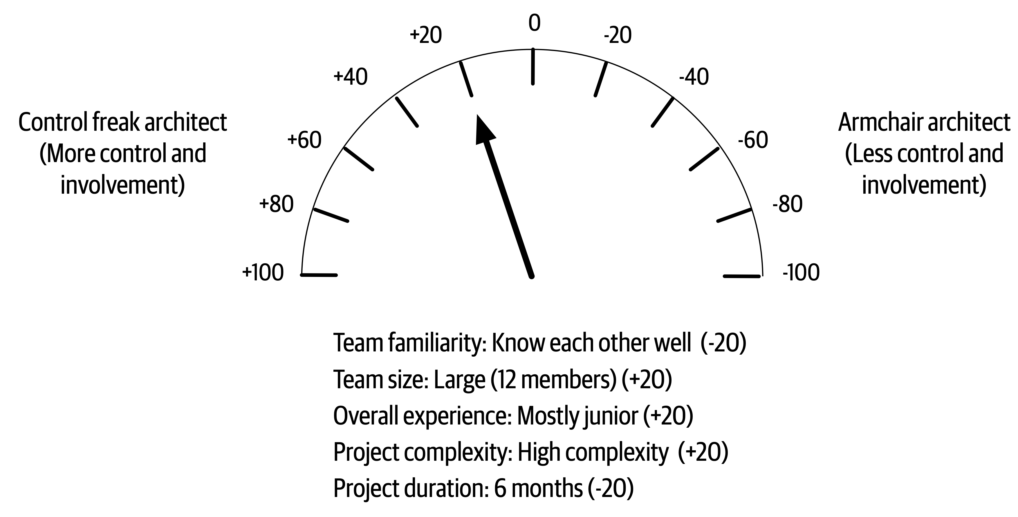
Figure 22-8. Amount of control for scenario 2
It is difficult to objectify these factors, as some of them (such as the overall team experience) might be more weighted than others. In these cases the metrics can easily be weighted or modified to suit any particular scenario or condition. Regardless, the primary message here is that the amount of control and involvement a software architect has on the team varies by these five main factors and that by taking these factors into account, an architect can gauge what sort of control to exert on the team and what the box in which development teams can work in should look like (tight boundaries and constraints or loose ones).
Team Warning Signs
-
Process loss
-
Pluralistic ignorance
-
Diffusion of responsibility
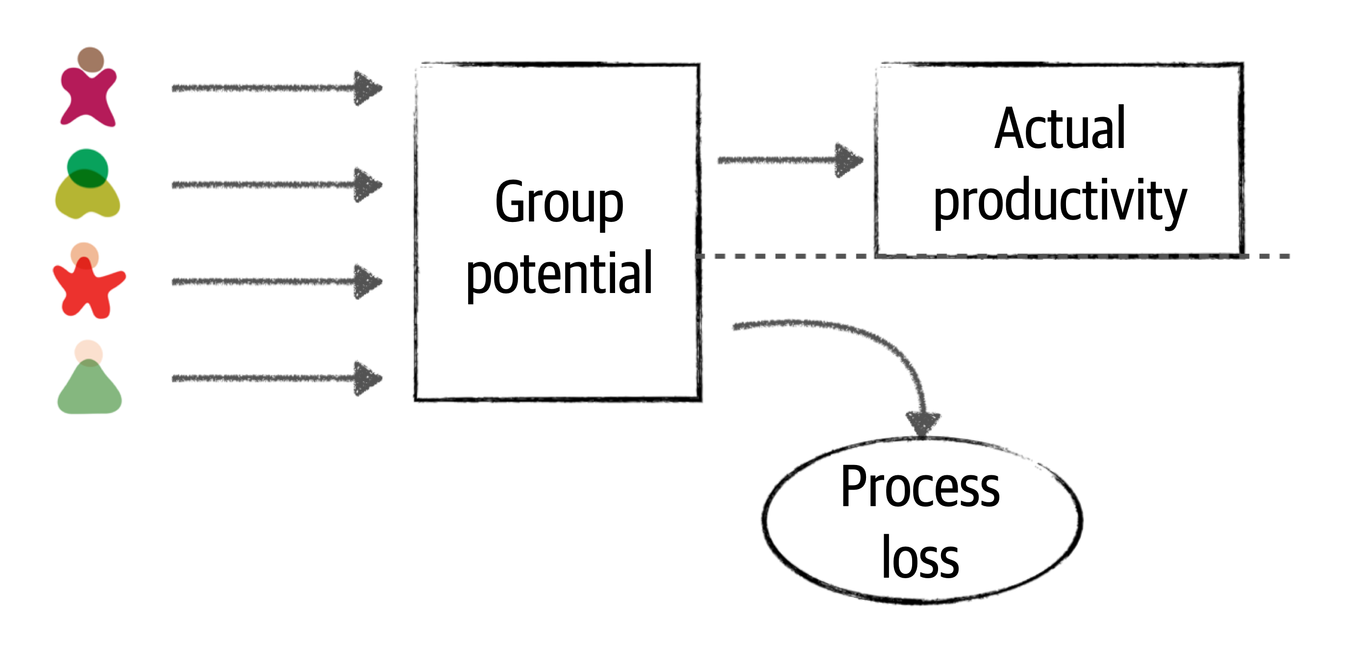
Figure 22-9. Team size impacts actual productivity (Brook’s law)
An effective software architect will observe the development team and look for process loss. Process loss is a good factor in determining the correct team size for a particular project or effort. One indication of process loss is frequent merge conflicts when pushing code to a repository. This is an indication that team members are possibly stepping on each other’s toes and working on the same code. Looking for areas of parallelism within the team and having team members working on separate services or areas of the application is one way to avoid process loss. Anytime a new team member comes on board a project, if there aren’t areas for creating parallel work streams, an effective architect will question the reason why a new team member was added to the team and demonstrate to the project manager the negative impact that additional person will have on the team.
Pluralistic ignorance also occurs as the team size gets too big. Pluralistic ignorance is when everyone agrees to (but privately rejects) a norm because they think they are missing something obvious. For example, suppose on a large team the majority agree that using messaging between two remote services is the best solution. However, one person on the team thinks this is a silly idea because of a secure firewall between the two services. However, rather than speak up, that person also agrees to the use of messaging (but privately rejects the idea) because they are afraid that they are either missing something obvious or afraid they might be seen as a fool if they were to speak up. In this case, the person rejecting the norm was correct—messaging would not work because of a secure firewall between the two remote services. Had they spoken up (and had the team size been smaller), the original solution would have been challenged and another protocol (such as REST) used instead, which would be a better solution in this case.
An effective software architect should continually observe facial expressions and body language during any sort of collaborative meeting or discussion and act as a facilitator if they sense an occurrence of pluralistic ignorance. In this case, the effective architect might interrupt and ask the person what they think about the proposed solution and be on their side and support them when they speak up.
The third factor that indicates appropriate team

Figure 22-10. Diffusion of responsibility
This picture shows someone standing next to a broken-down car on the side of a small country road. In this scenario, how many people might stop and ask the motorist if everything is OK? Because it’s a small road in a small community, probably everyone who passes by. However, how many times have motorists been stuck on the side of a busy highway in the middle of a large city and had thousands of cars simply drive by without anyone stopping and asking if everything is OK? All the time. This is a good example of the diffusion of responsibility. As cities get busier and more crowded, people assume the motorist has already called or help is on the way due to the large number of people witnessing the event. However, in most of these cases help is not on the way, and the motorist is stuck with a dead or forgotten cell phone, unable to call for help.
An effective architect not only helps guide the development team through the implementation of the architecture, but also ensures that the team is healthy, happy, and working together to achieve a common goal. Looking for these three warning signs and consequently helping to correct them helps to ensure an effective development team.
Leveraging Checklists
Checklists work. They provide an excellent vehicle for making sure everything is covered and addressed. If checklists work so well, then why doesn’t the software development industry leverage them? We firmly believe through personal experience that checklists make a big difference in the effectiveness of development teams. However, there are caveats to this claim. First, most software developers are not flying airliners or performing open heart surgery. In other words, software developers don’t require checklists for everything. The key to making teams effective is knowing when to leverage checklists and when not to.
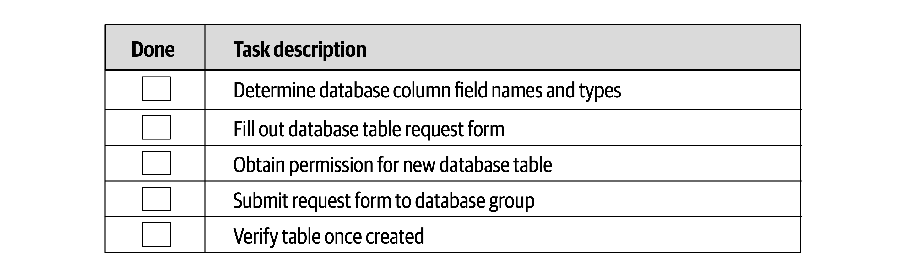
Figure 22-11. Example of a bad checklist
This is not a checklist, but a set of procedural steps, and as such should not be in a checklist. For example, the database table cannot be verified if the form has not yet been submitted! Any processes that have a procedural flow of dependent tasks should not be in a checklist. Simple, well-known processes that are executed frequently without error also do not need a checklist.
Processes that are good candidates for checklists are those that don’t have any procedural order or dependent tasks, as well as those that tend to be error-prone or have steps that are frequently missed or skipped. The key to making checklists effective is to not go overboard making everything a checklist. Architects find that checklists do, in fact, make development teams more effective, and as such start to make everything a checklist, invoking what is known as the law of diminishing returns. The more checklists an architect creates, the less chance developers will use them. Another key success factor when creating checklists is to make them as small as possible while still capturing all the necessary steps within a process. Developers generally will not follow checklists that are too big. Seek items that can be performed through automation and remove those from the checklist.
Tip
Don’t worry about stating the obvious in a checklist. It’s the obvious stuff that’s usually skipped or missed.
Three key checklists that we’ve found to be most effective are a developer code completion checklist, a unit and functional testing checklist, and a software release checklist. Each checklist is discussed in the following sections.
Developer Code Completion Checklist
Here are some of the things to include in a developer code completion checklist:
-
Coding and formatting standards not included in automated tools
-
Frequently overlooked items (such as absorbed exceptions)
-
Project-specific standards
-
Special team instructions or procedures
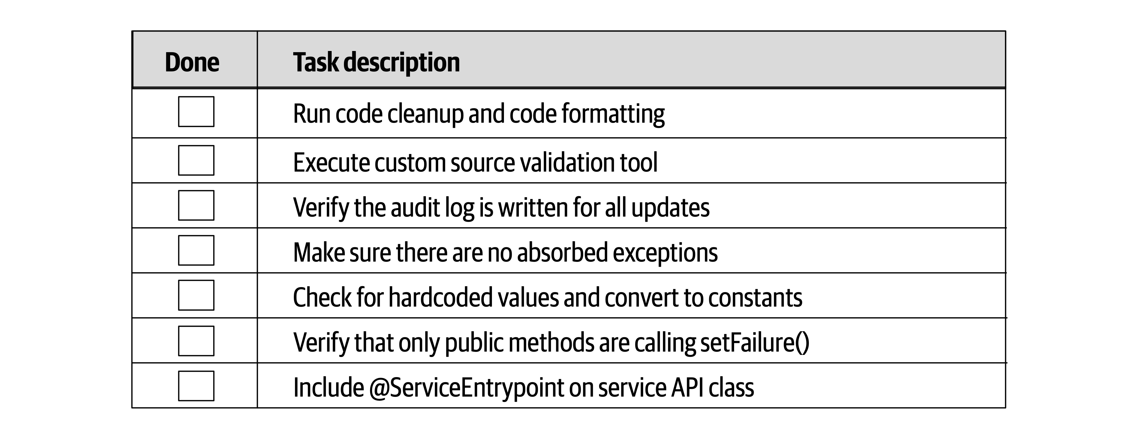
Figure 22-12. Example of a developer code completion checklist
Notice the obvious tasks “Run code cleanup and code formatting” and “Make sure there are no absorbed exceptions” in the checklist. How may times has a developer been in a hurry either at the end of the day or at the end of an iteration and forgotten to run code cleanup and formatting from the IDE? Plenty of times. In The Checklist Manifesto, Gawande found this same phenomenon with respect to surgical procedures—the obvious ones were often the ones that were usually missed.
Notice also the project-specific tasks in items 2, 3, 6, and 7. While these are good items to have in a checklist, an architect should always review the checklist to see if any items can be automated or written as plug-in for a code validation checker. For example, while “Include @ServiceEntrypoint on service API class” might not be able to have an automated check, the “Verify that only public methods are calling setFailure()” certainly can (this is a straightforward automated check with any sort of code crawling tool). Checking for areas of automation helps reduce both the size and the noise within a checklist, making it more effective.
Unit and Functional Testing Checklist
Perhaps one of the most effective checklists is a unit and functional testing checklist. This checklist contains some of the more unusual and edge-case tests that software developers tend to forget to test.
This particular checklist is usually one of the largest ones due to all the types of tests that can be run against code. The purpose of this checklist is to ensure the most complete coding possible so that when the developer is done with the checklist, the code is essentially production ready.
Here are some of the items found in a typical unit and functional testing checklist:
-
Special characters in text and numeric fields
-
Minimum and maximum value ranges
-
Unusual and extreme test cases
-
Missing fields
Like the developer code completion checklist, any items that can be written as automated tests should be removed from the checklist. For example, suppose there is an item in the checklist for a stock trading application to test for negative shares (such as a BUY for –1,000 shares of Apple [AAPL]). If this check is automated through a unit or functional test within the test suite, then the item should be removed from the checklist.
Developers sometimes don’t know where to start when writing unit tests or how many unit tests to write. This checklist provides a way of making sure general or specific test scenarios are included in the process of developing the software. This checklist is also effective in bridging the gap between developers and testers in environments that have these activities performed by separate teams. The more development teams perform complete testing, the easier the job of the testing teams, allowing the testing teams to focus on certain business scenarios not covered in the checklists.
Software Release Checklist
The software release checklist is usually the most volatile of the checklists in that it continually changes to address new errors and circumstances each time a deployment fails or has issues.
Here are some of the items typically included within the software release checklist:
-
Configuration changes in servers or external configuration servers
-
Third-party libraries added to the project (JAR, DLL, etc.)
-
Database updates and corresponding database migration scripts
Providing Guidance
Using this example, an effective software architect can provide guidance to the development team by first having the developer answer the following questions:
-
Are there any overlaps between the proposed library and existing functionality within the system?
-
What is the justification for the proposed library?
The first question guides developers to looking at the existing libraries to see if the functionality provided by the new library can be satisfied through an existing library or existing functionality. It has been our experience that developers sometimes ignore this activity, creating lots of duplicate functionality, particularly in large projects with large teams.
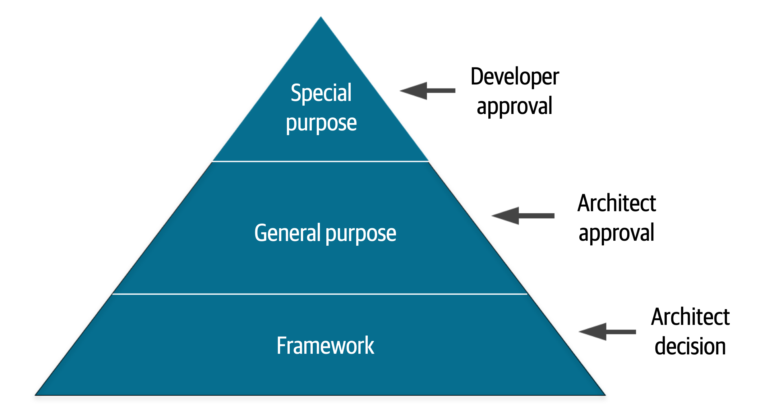
Figure 22-13. Providing guidance for the layered stack
- Special purpose
-
These are specific libraries used for things like PDF rendering, bar code scanning, and circumstances that do not warrant writing custom software.
- General purpose
-
These libraries are wrappers on top of the language API, and they include things like Apache Commons, and Guava for Java.
- Framework
-
These libraries are used for things like persistence (such as Hibernate) and inversion of control (such as Spring). In other words, these libraries make up an entire layer or structure of the application and are highly invasive.
Once categorized (the preceding categories are only an example—there can be many more defined), the architect then creates the box around this design principle. Notice in the example illustrated in Figure 22-13 that for this particular application or project, the architect has specified that for special-purpose libraries, the developer can make the decision and does not need to consult the architect for that library. However, notice that for general purpose, the architect has indicated that the developer can undergo overlap analysis and justification to make the recommendation, but that category of library requires architect approval. Finally, for framework libraries, that is an architect decision—in other words, the development teams shouldn’t even undergo analysis for these types of libraries; the architect has decided to take on that responsibility for those types of libraries.
Summary
Chapter 23. Negotiation and Leadership Skills
Negotiation and leadership skills are hard skills to obtain.
Negotiation and Facilitation
Consider the decision of an architect to use database clustering and federation (using separate physical domain-scoped database instances) to mitigate risk with regard to overall availability within a system. While this is a sound solution to the issue of database availability, it is also a costly decision. In this example, the architect must negotiate with key business stakeholders (those paying for the system) to come to an agreement about the trade-off between availability and cost.
Negotiation is one of the most important skills a software architect can have. Effective software architects understand the politics of the organization, have strong negotiation and facilitation skills, and can overcome disagreements when they occur to create solutions that all stakeholders agree on.
Negotiating with Business Stakeholders
- Scenario 1
-
The senior vice president project sponsor is insistent that the new trading system must support five nines of availability (99.999%). However, the lead architect is convinced, based on research, calculations, and knowledge of the business domain and technology, that three nines of availability (99.9%) would be sufficient. The problem is, the project sponsor does not like to be wrong or corrected and really hates people who are condescending. The sponsor isn’t overly technical (but thinks they are) and as a result tends to get involved in the nonfunctional aspects of projects. The architect must convince the project sponsor through negotiation that three nines (99.9%) of availability would be enough.
In this sort of negotiation, the software architect must be careful to not be too egotistical and forceful in their analysis, but also make sure they are not missing anything that might prove them wrong during the negotiation. There are several key negotiation techniques an architect can use to help with this sort of stakeholder negotiation.
Tip
Leverage the use of grammar and buzzwords to better understand the situation.
Phases such as “we must have zero downtime” and “I needed those features yesterday” are generally meaningless but nevertheless provide valuable information to the architect about to enter into a negotiation. For example, when the project sponsor is asked when a particular feature is needed and responds, “I needed it yesterday,” that is an indication to the software architect that time to market is important to that stakeholder. Similarly, the phrase “this system must be lightning fast” means performance is a big concern. The phase “zero downtime” means that availability is critical in the application. An effective software architect will leverage this sort of nonsense grammar to better understand the real concerns and consequently leverage that use of grammar during a negotiation.
Consider scenario 1 described previously. Here, the key project sponsor wants five nines of availability. Leveraging this technique tells the architect that availability is very important. This leads to a second negotiation technique:
Tip
Gather as much information as possible before entering into a negotiation.
| Percentage uptime | Downtime per year (per day) |
|---|---|
90.0% (one nine) | 36 days 12 hrs (2.4 hrs) |
99.0% (two nines) | 87 hrs 46 min (14 min) |
99.9% (three nines) | 8 hrs 46 min (86 sec) |
99.99% (four nines) | 52 min 33 sec (7 sec) |
99.999% (five nines) | 5 min 35 sec (1 sec) |
99.9999% (six nines) | 31.5 sec (86 ms) |
“Five nines” of availability is 5 minutes and 35 seconds of downtime per year, or 1 second a day of unplanned downtime. Quite ambitious, but also quite costly and unnecessary for the prior example. Putting things in hours and minutes (or in this case, seconds) is a much better way to have the conversation than sticking with the nines vernacular.
Negotiating scenario 1 would include validating the stakeholder’s concerns (“I understand that availability is very important for this system”) and then bringing the negotiation from the nines vernacular to one of reasonable hours and minutes
Tip
When all else fails, state things in terms of cost and time.
We recommend saving this negotiation tactic for last. We’ve seen too many negotiations start off on the wrong foot due to opening statements such as, “That’s going to cost a lot of money” or “We don’t have time for that.” Money and time (effort involved) are certainly key factors in any negotiation but should be used as a last resort so that other justifications and rationalizations that matter more be tried first. Once an agreement is reached, then cost and time can be considered if they are important attributes to the negotiation.
Tip
Leverage the “divide and conquer” rule to qualify demands or requirements.
Negotiating with Other Architects
- Scenario 2
-
The lead architect on a project believes that asynchronous messaging would be the right approach for communication between a group of services to increase both performance and scalability. However, the other architect on the project once again strongly disagrees and insists that REST would be a better choice, because REST is always faster than messaging and can scale just as well (“see for yourself by Googling it!”). This is not the first heated debate between the two architects, nor will it be the last. The lead architect must convince the other architect that messaging is the right solution.
Tip
Always remember that demonstration defeats discussion.
Rather than arguing with another architect over the use of REST versus messaging, the lead architect should demonstrate to the other architect how messaging would be a better choice in their specific environment. Every environment is different, which is why simply Googling it will never yield the correct answer. By running a comparison between the two options in a production-like environment and showing the other architect the results, the argument would likely be avoided.
Another key negotiation technique that works in these situations is as follows:
Tip
This technique is a very powerful tool when dealing with adversarial relationships like the one described in scenario 2. Once things get too personal or argumentative, the best thing to do is stop the negotiation and reengage at a later time when both parties have calmed down. Arguments will happen between architects; however, approaching these situations with calm leadership will usually force the other person to back down when things get too heated.
Negotiating with Developers
Tip
When convincing developers to adopt an architecture decision or to do a specific task, provide a justification rather than “dictating from on high.”
By providing a reason why something needs to be done, developers will more likely agree with the request. For example, consider the following conversation between an architect and a developer with regard to making a simple query within a traditional n-tiered layered architecture:
Architect: “You must go through the business layer to make that call.”
Developer: “No. It’s much faster just to call the database directly.”
There are several things wrong with this conversation. First, notice the use of the words “you must.” This type of commanding voice is not only demeaning, but is one of the worst ways to begin a negotiation or conversation. Also notice that the developer responded to the architect’s demand with a reason to counter the demand (going through the business layer will be slower and take more time). Now consider an alternative approach to this demand:
Architect: “Since change control is most important to us, we have formed a closed-layered architecture. This means all calls to the database need to come from the business layer.”
Developer: “OK, I get it, but in that case, how am I going to deal with the performance issues for simple queries?”
Notice here the architect is providing the justification for the demand that all requests need to go through the business layer of the application. Providing the justification or reason first is always a good approach. Most of the time, once a person hears something they disagree with, they stop listening. By stating the reason first, the architect is sure that the justification will be heard. Also notice the architect removed the personal nature of this demand. By not saying “you must” or “you need to,” the architect effectively turned the demand into a simple statement of fact (“this means…”). Now take a look at the developer’s response. Notice the conversation shifted from disagreeing with the layered architecture restrictions to a question about increasing performance for simple calls. Now the architect and developer can engage in a collaborative conversation to find ways to make simple queries faster while still preserving the closed layers in the architecture.
Another effective negotiation tactic when negotiating with a developer or trying to convince them to accept a particular design or architecture decision they disagree with is to have the developer arrive at the solution on their own. This creates a win-win situation where the architect cannot lose. For example, suppose an architect is choosing between two frameworks, Framework X and Framework Y. The architect sees that Framework Y doesn’t satisfy the security requirements for the system and so naturally chooses Framework X. A developer on the team strongly disagrees and insists that Framework Y would still be the better choice. Rather than argue the matter, the architect tells the developer that the team will use Framework Y if the developer can show how to address the security requirements if Framework Y is used. One of two things will happen:
-
The developer will fail trying to demonstrate that Framework Y will satisfy the security requirements and will understand firsthand that the framework cannot be used. By having the developer arrive at the solution on their own, the architect automatically gets buy-in and agreement for the decision to use Framework X by essentially making it the developer’s decision. This is a win.
-
The developer finds a way to address the security requirements with Framework Y and demonstrates this to the architect. This is a win as well. In this case the architect missed something in Framework Y, and it also ended up being a better framework over the other one.
Tip
If a developer disagrees with a decision, have them arrive at the solution on their own.
It’s really through collaboration with the development team that the architect is able to gain the respect of the team and form better solutions. The more developers respect an architect, the easier it will be for the architect to negotiate with those developers.
The Software Architect as a Leader
The 4 C’s of Architecture
Developers are drawn to complexity like moths to a flame—frequently with the same result.
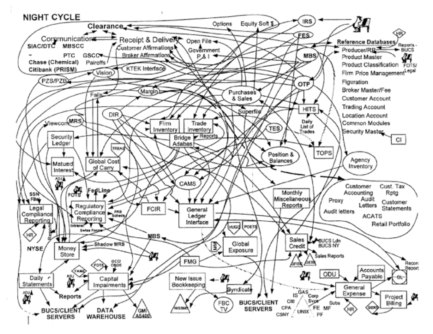
Figure 23-1. Introducing accidental complexity into a problem
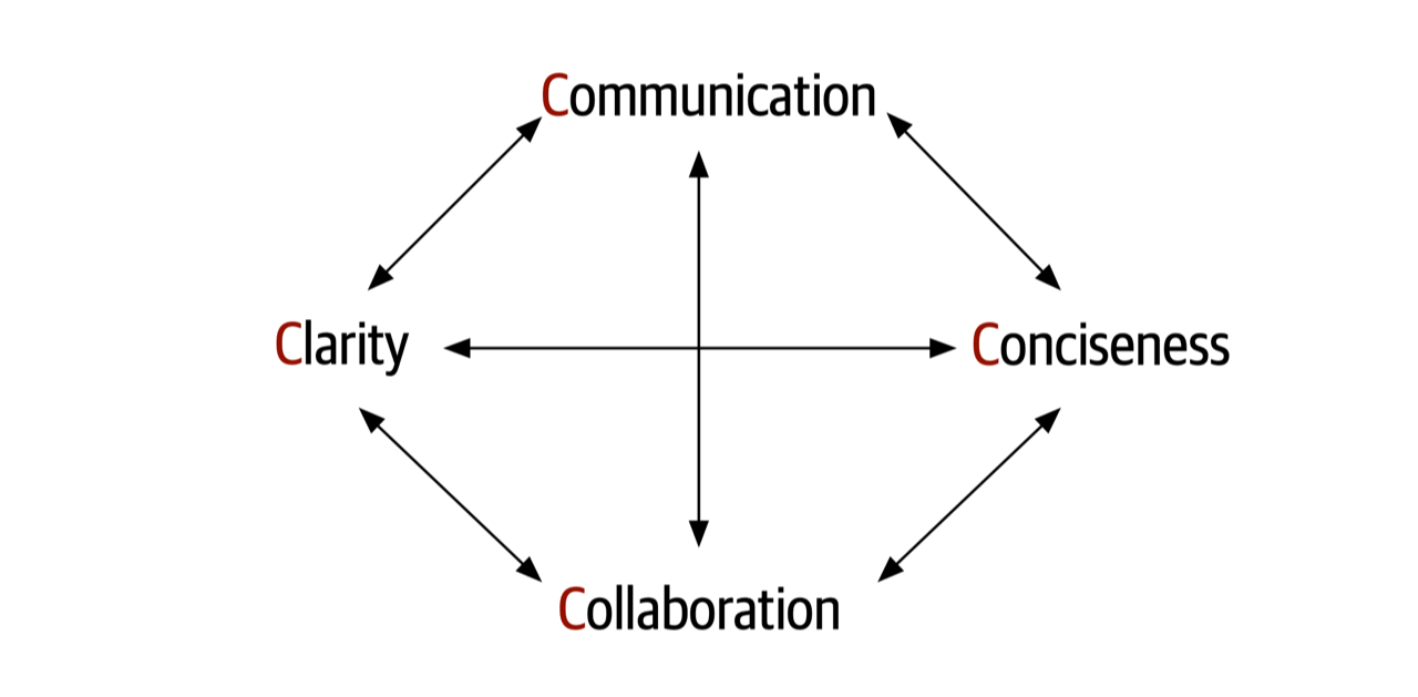
Figure 23-2. The 4 C’s of architecture
As a leader, facilitator, and negotiator, is it vital that a software architect be able to effectively communicate in a clear and concise manner. It is equally important that an architect also be able to collaborate with developers, business stakeholders, and other architects to discuss and form solutions together. Focusing on the 4 C’s of architecture helps an architect gain the respect of the team and become the go-to person on the project that everyone comes to not only for questions, but also for advice, mentoring, coaching, and leadership.
Be Pragmatic, Yet Visionary
An effective software architect must be pragmatic, yet visionary.
- Visionary
Thinking about or planning the future with imagination or wisdom.
- Pragmatic
Dealing with things sensibly and realistically in a way that is based on practical rather than theoretical considerations.
While architects need to be visionaries, they also need to apply practical and realistic solutions. Being pragmatic is taking all of the following factors and constraints into account when creating an architectural solution:
-
Budget constraints and other cost-based factors
-
Time constraints and other time-based factors
-
Skill set and skill level of the development team
-
Trade-offs and implications associated with an architecture decision
-
Technical limitations of a proposed architectural design or solution
A pragmatic architect would first look at what the limiting factor is when needing high levels of elasticity. Is it the database that’s the bottleneck? Maybe it’s a bottleneck with respect to some of the services invoked or other external sources needed. Finding and isolating the bottleneck would be a first practical approach to the problem. In fact, even if it is the database, could some of the data needed be cached so that the database need not be accessed at all?

Figure 23-3. Good architects find the balance between being pragmatic, yet visionary
Maintaining a good balance between being pragmatic, yet visionary, is an excellent way of gaining respect as an architect. Business stakeholders will appreciate visionary solutions that fit within a set of constraints, and developers will appreciate having a practical (rather then theoretical) solution to implement.
Leading Teams by Example
The classic “lead by example, not by title” story involves a captain and a sergeant during a military battle. The high-ranking captain, who is largely removed from the troops, commands all of the troops to move forward during the battle to take a particularly difficult hill. However, rather than listen to the high-ranking captain, the soldiers, full of doubt, look over to the lower-ranking sergeant for whether they should take the hill or not. The sergeant looks at the situation, nods his head slightly, and the soldiers immediately move forward with confidence to take the hill.
Gaining respect and leading teams is about basic people skills. Consider the following dialogue between an architect and a customer, client, or development team with regard to a performance issue in the application:
Developer: “So how are we going to solve this performance problem?”
Architect: “What you need to do is use a cache. That would fix the problem.”
Developer: “Don’t tell me what to do.”
Architect: “What I’m telling you is that it would fix the problem.”
By using the words “what you need to do is…” or “you must,” the architect is forcing their opinion onto the developer and essentially shutting down collaboration. This is a good example of using communication, not collaboration. Now consider the revised dialogue:
Developer: “So how are we going to solve this performance problem?”
Architect: “Have you considered using a cache? That might fix the problem.”
Developer: “Hmmm, no we didn’t think about that. What are your thoughts?”
Architect: “Well, if we put a cache here…”
Notice the use of the words “have you considered…” or “what about…” in the dialogue. By asking the question, it puts control back on the developer or client, creating a collaborative conversation where both the architect and developer are working together to form a solution. The use of grammar is vitally important when trying to build a collaborative environment. Being a leader as an architect is not only being able to collaborate with others to create an architecture, but also to help promote collaboration among the team by acting as a facilitator. As an architect, try to observe team dynamics and notice when situations like the first dialogue occurs. By taking team members aside and coaching them on the use of grammar as a means of collaboration, not only will this create better team dynamics, but it will also help create respect among the team members.
Another basic people skills technique that can help build respect and healthy relationships between an architect and the development team is to always try to use the person’s name during a conversation or negotiation. Not only do people like hearing their name during a conversation, it also helps breed familiarity. Practice remembering people’s names, and use them frequently. Given that names are sometimes hard to pronounce, make sure to get the pronunciation correct, then practice that pronunciation until it is perfect. Whenever we ask someone’s name, we repeat it to the person and ask if that’s the correct way to pronounce it. If it’s not correct, we repeat this process until we get it right.
If an architect meets someone for the first time or only occasionally, always shake the person’s hand and make eye contact. A handshake is an important people skill that goes back to medieval times. The physical bond that occurs during a simple handshake lets both people know they are friends, not foes, and forms a bond between the two people. However, while very basic, it is sometimes hard to get a simple handshake right.
When shaking someone’s hand, give a firm (but not overpowering) handshake while looking the person in the eye. Looking away while shaking someone’s hand is a sign of disrespect, and most people will notice that. Also, don’t hold on to the handshake too long. A simple two- to three-second, firm handshake is all that is needed to start off a conversation or to greet someone. There is also the issue of going overboard with the handshake technique and making the other person uncomfortable enough to not want to communicate or collaborate with you. For example, imagine a software architect who comes in every morning and starts shaking everyone’s hand. Not only is this a little weird, it creates an uncomfortable situation. However, imagine a software architect who must meet with the head of operations monthly. This is the perfect opportunity to stand up, say “Hello Ruth, nice seeing you again,” and give a quick, firm handshake. Knowing when to do a handshake and when not to is part of the complex art of people skills.
A software architect as a leader, facilitator, and negotiator should be careful to preserve the boundaries that exist between people at all levels. The handshake, as described previously, is an effective and professional technique of forming a physical bond with the person you are communicating or collaborating with. However, while a handshake is good, a hug in a professional setting, regardless of the environment, is not. An architect might think that it exemplifies more physical connection and bonding, but all it does is sometimes make the other person at work more uncomfortable and, more importantly, can lead to potential harassment issues within the workplace. Skip the hugs all together, regardless of the professional environment, and stick with the handshake instead (unless of course everyone in the company hugs each other, which would just be…weird).
Sometimes it’s best to turn a request into a favor as a way of getting someone to do something they otherwise might not want to do. In general, people do not like to be told what to do, but for the most part, people want to help others. This is basic human nature. Consider the following conversation between an architect and developer regarding an architecture refactoring effort during a busy iteration:
Architect: “I’m going to need you to split the payment service into five different services, with each service containing the functionality for each type of payment we accept, such as store credit, credit card, PayPal, gift card, and reward points, to provide better fault tolerance and scalability in the website. It shouldn’t take too long.”
Developer: “No way, man. Way too busy this iteration for that. Sorry, can’t do it.”
Architect: “Listen, this is important and needs to be done this iteration.”
Developer: “Sorry, no can do. Maybe one of the other developers can do it. I’m just too busy.”
Notice the developer’s response. It is an immediate rejection of the task, even though the architect justified it through better fault tolerance and scalability. In this case, notice that the architect is telling the developer to do something they are simply too busy to do. Also notice the demand doesn’t even include the person’s name!
Now consider the technique of turning the request into a favor:
Architect: “Hi, Sridhar. Listen, I’m in a real bind. I really need to have the payment service split into separate services for each payment type to get better fault tolerance and scalability, and I waited too long to do it. Is there any way you can squeeze this into this iteration? It would really help me out.”
Developer: “(Pause)…I’m really busy this iteration, but I guess so. I’ll see what I can do.”
Architect: “Thanks, Sridhar, I really appreciate the help. I owe you one.”
Developer: “No worries, I’ll see that it gets done this iteration.”
First, notice the use of the person’s name repeatedly throughout the conversation. Using the person’s name makes the conversation more of a personal, familiar nature rather than an impersonal professional demand. Second, notice the architect admits they are in a “real bind” and that splitting the services would really “help them out a lot.” This technique does not always work, but playing off of basic human nature of helping each other has a better probability of success over the first conversation. Try this technique the next time you face this sort of situation and see the results. In most cases, the results will be much more positive than telling someone what to do.
To lead a team and become an effective leader, a software architect should try to become the go-to person on the team—the person developers go to for their questions and problems. An effective software architect will seize the opportunity and take the initiative to lead the team, regardless of their title or role on the team. When a software architect observes someone struggling with a technical issue, they should step in and offer help or guidance. The same is true for nontechnical situations as well. Suppose an architect observes a team member that comes into work looking sort of depressed and bothered—clearly something is up. In this circumstance, an effective software architect would notice the situation and offer to talk—something like, “Hey, Antonio, I’m heading over to get some coffee. Why don’t we head over together?” and then during the walk ask if everything is OK. This at least provides an opening for more of a personal discussion; and at it’s best, a chance to mentor and coach at a more personal level. However, an effective leader will also recognize times to not be too pushy and will back off by reading various verbal signs and facial expressions.
Integrating with the Development Team
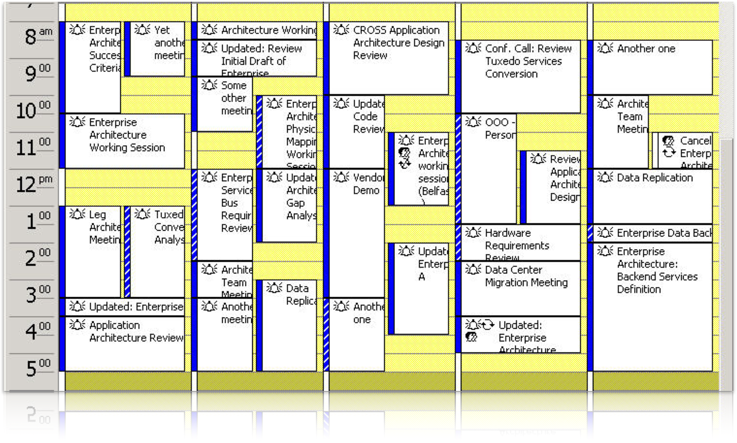
Figure 23-4. A typical calendar of a software architect
The key to being an effective software architect is making more time for the development team, and this means controlling meetings.
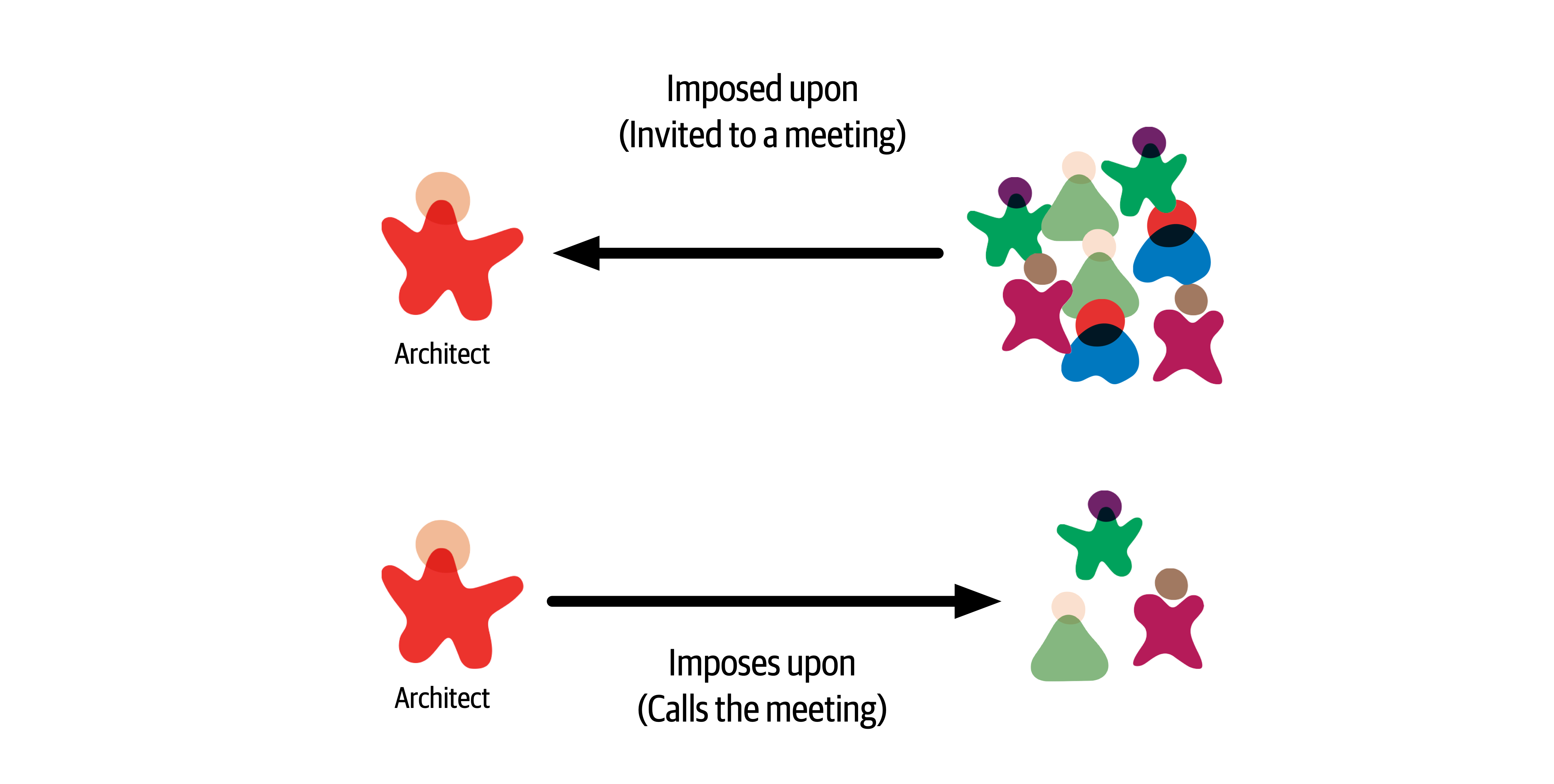
Figure 23-5. Meeting types
Imposed upon meetings are the hardest to control. Due to the number of stakeholders a software architect must communicate and collaborate with, architects are invited to almost every meeting that gets scheduled. When invited to a meeting, an effective software architect should always ask the meeting organizer why they are needed in that meeting. Many times architects get invited to meetings simply to keep them in the loop on the information being discussed. That’s what meeting notes are for. By asking why, an architect can start to qualify which meetings they should attend and which ones they can skip. Another related technique to help reduce the number of meetings an architect is involved in is to ask for the meeting agenda before accepting a meeting invite. The meeting organizer may feel that the architect is necessary, but by looking at the agenda, the architect can qualify whether they really need to be in the meeting or not. Also, many times it is not necessary to attend the entire meeting. By reviewing the agenda, an architect can optimize their time by either showing up when relevant information is being discussed or leaving after the relevant discussion is over. Don’t waste time in a meeting if you can be spending that time working with the development team.
Tip
Ask for the meeting agenda ahead of time to help qualify if you are really needed at the meeting or not.
Another effective technique to keep a development team on track and to gain their respect is to take one for the team when developers are invited to a meeting as well. Rather than having the tech lead attend the meeting, go in their place, particularly if both the tech lead and architect are invited to a meeting. This keeps a development team focused on the task at hand rather than continually attending meetings as well. While deflecting meetings away from useful team members increases the time an architect is in meetings, it does increase the development team’s productivity.
Meetings that an architect imposes upon others (the architect calls the meeting) are also a necessity at times but should be kept to an absolute minimum. These are the kinds of meetings an architect has control over. An effective software architect will always ask whether the meeting they are calling is more important than the work they are pulling their team members away from. Many times an email is all that is required to communicate some important information, which saves everyone tons of wasted time. When calling a meeting as an architect, always set an agenda and stick to it. Too often, meetings an architect calls get derailed due to some other issue, and that other issue may not be relevant to everyone else in the meeting. Also, as an architect, pay close attention to developer flow and be sure not to disrupt it by calling a meeting.
Aside from managing meetings, another thing an effective software architect can do to integrate better with the development team is to sit with that team. Sitting in a cubicle away from the team sends the message that the architect is special, and those physical walls surrounding the cubicle are a distinct message that the architect is not to be bothered or disturbed. Sitting alongside a development team sends the message that the architect is an integral part of the team and is available for questions or concerns as they arise. By physically showing that they are part of the development team, the architect gains more respect and is better able to help guide and mentor the team.
Summary
The most important single ingredient in the formula of success is knowing how to get along with people.
Theodore Roosevelt
Chapter 24. Developing a Career Path
Becoming an architect takes time and effort, but based on the many reasons we’ve outlined throughout this book, managing a career path after becoming an architect is equally tricky.
An architect must continue to learn throughout their career. The technology world changes at a dizzying pace. One of Neal’s former coworkers was a world-renowned expert in Clipper. He lamented that he couldn’t take the enormous body of (now useless) Clipper knowledge and replace it with something else. He also speculated (and this is still an open question): has any group in history learned and thrown away so much detailed knowledge within their lifetimes as software developers?
Each architect should keep an eye out for relevant resources, both technology and business, and add them to their personal stockpile. Unfortunately, resources come and go all too quickly, which is why we don’t list any in this book. Talking to colleagues or experts about what resources they use to keep current is one good way of seeking out the latest newsfeeds, websites, and groups that are active in a particular area of interest. Architects should also build into their day some time to maintain breadth utilizing those resources.
The 20-Minute Rule
Figure 24-1. The 20-minute rule
Many architects embrace this concept and plan to spend 20 minutes at lunch or in the evening after work to do this. What we have experienced is that this rarely works. Lunchtime gets shorter and shorter, becoming more of a catch-up time at work rather than a time to take a break and eat. Evenings are even worse—situations change, plans get made, family time becomes more important, and the 20-minute rule never happens.
We strongly recommend leveraging the 20-minute rule first thing in the morning, as the day is starting. However, there is a caveat to this advice as well. For example, what is the first thing an architect does after getting to work in the morning? Well, the very first thing the architect does is to get that wonderful cup of coffee or tea. OK, in that case, what is the second thing every architect does after getting that necessary coffee or tea—check email. Once an architect checks email, diversion happens, email responses are written, and the day is over. Therefore, our strong recommendation is to invoke the 20-minute rule first thing in the morning, right after grabbing that cup of coffee or tea and before checking email. Go in to work a little early. Doing this will increase an architect’s technical breadth and help develop the knowledge required to become an effective software architect.
Developing a Personal Radar
What they lacked was a technology radar: a living document to assess the risks and rewards of existing and nascent technologies. The radar concept comes from ThoughtWorks; first, we’ll describe how this concept came to be and then how to use it to create a personal radar.
The ThoughtWorks Technology Radar
The TAB gradually settled into a twice-a-year rhythm of Radar production. Then, as often happens, unexpected side effects occurred. At some of the conferences Neal spoke at, attendees sought him out and thanked him for helping produce the Radar and said that their company had started producing their own version of it.
Neal also realized that this was the answer to a pervasive question at conference speaker panels everywhere: “How do you (the speakers) keep up with technology? How do you figure out what things to pursue next?” The answer, of course, is that they all have some form of internal radar.
Parts
- Tools
-
Tools in the software development space, everything from developers tools like IDEs to enterprise-grade integration tools
- Languages and frameworks
-
Computer languages, libraries, and frameworks, typically open source
- Techniques
-
Any practice that assists software development overall; this may include software development processes, engineering practices, and advice
- Platforms
- Technology platforms, including databases, cloud vendors, and operating systems
Rings
The Radar has four rings, listed here from outer to inner:
- Hold
-
The original intent of the hold ring was “hold off for now,” to represent technologies that were too new to reasonably assess yet—technologies that were getting lots of buzz but weren’t yet proven. The hold ring has evolved into indicating “don’t start anything new with this technology.” There’s no harm in using it on existing projects, but developers should think twice about using it for new development.
- Assess
-
The assess ring indicates that a technology is worth exploring with the goal of understanding how it will affect an organization. Architects should invest some effort (such as development spikes, research projects, and conference sessions) to see if it will have an impact on the organization. For example, many large companies visibly went through this phase when formulating a mobile strategy.
- Trial
-
The trial ring is for technologies worth pursuing; it is important to understand how to build up this capability. Now is the time to pilot a low-risk project so that architects and developers can really understand the technology.
- Adopt
-
For technologies in the adopt ring, ThoughtWorks feels strongly that the industry should adopt those items.
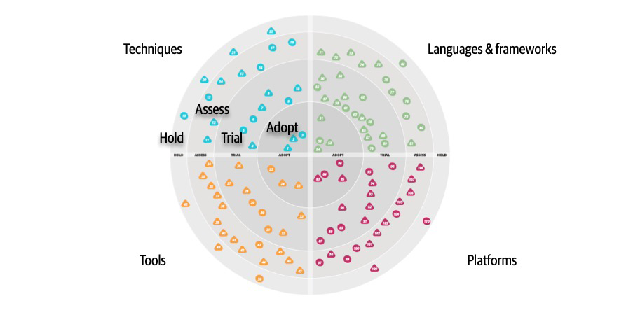
Figure 24-2. A sample ThoughtWorks Technology Radar
In Figure 24-2, each blip represents a different technology or technique, with associated short write-ups.
While ThoughtWorks uses the radar to broadcast their opinions about the software world, many developers and architects also use it as a way of structuring their technology assessment process. Architects can use the tool described in “Open Source Visualization Bits” to build the same visuals used by ThoughtWorks as a way to organize their thinking about what to invest time in.
When using the radar for personal use, we suggest altering the meanings of the quadrants to the following:
- Hold
-
An architect can include not only technologies and techniques to avoid, but also habits they are trying to break. For example, an architect from the .NET world may be accustomed to reading the latest news/gossip on forums about team internals. While entertaining, it may be a low-value information stream. Placing that in hold forms a reminder for an architect to avoid problematic things.
- Assess
-
Architects should use assess for promising technologies that they have heard good things about but haven’t had time to assess for themselves yet—see “Using Social Media”. This ring forms a staging area for more serious research at some time in the future.
- Trial
-
The trial ring indicates active research and development, such as an architect performing spike experiments within a larger code base. This ring represents technologies worth spending time on to understand more deeply so that an architect can perform an effective trade-off analysis.
- Adopt
-
The adopt ring represents the new things an architect is most excited about and best practices for solving particular problems.
It is dangerous to adopt a laissez-faire attitude toward a technology portfolio. Most technologists pick technologies on a more or less ad hoc basis, based on what’s cool or what your employer is driving. Creating a technology radar helps an architect formalize their thinking about technology and balance opposing decision criteria (such as the “more cool” technology factor and being less likely to get a new job versus a huge job market but with less interesting work). Architects should treat their technology portfolio like a financial portfolio: in many ways, they are the same thing. What does a financial planner tell people about their portfolio? Diversify!
Architects should choose some technologies and/or skills that are widely in demand and track that demand. But they might also want to try some technology gambits, like open source or mobile development. Anecdotes abound about developers who freed themselves from cubicle-dwelling servitude by working late at night on open source projects that became popular, purchasable, and eventually, career destinations. This is yet another reason to focus on breadth rather than depth.
Architects should set aside time to broaden their technology portfolio, and building a radar provides a good scaffolding. However, the exercise is more important than the outcome. Creating the visualization provides an excuse to think about these things, and, for busy architects, finding an excuse to carve out time in a busy schedule is the only way this kind of thinking can occur.
Open Source Visualization Bits
Using Social Media
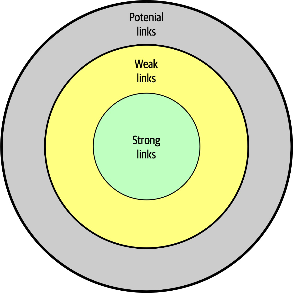
Figure 24-3. Social circles of a person’s relationships
In Figure 24-3, strong links represent family members, coworkers, and other people whom a person regularly contacts. One litmus test for how close these connections are: they can tell you what a person in their strong links had for lunch at least one day last week. Weak links are casual acquaintances, distant relatives, and other people seen only a few times a year. Before social media, it was difficult to keep up with this circle of people. Finally, potential links represent people you haven’t met yet.
McAfee’s most interesting observation about these connections was that someone’s next job is more likely to come from a weak link than a strong one. Strongly linked people know everything within the strongly linked group—these are people who see each other all the time. Weak links, on the other hand, offer advice from outside someone’s normal experience, including new job offers.
Using the characteristics of social networks, architects can utilize social media to enhance their technical breadth. Using social media like Twitter professionally, architects should find technologists whose advice they respect and follow them on social media. This allows an architect to build a network on new, interesting technologies to assess and keep up with the rapid changes in the technology world.
Parting Words of Advice
How do we get great designers? Great designers design, of course.
Fred Brooks
So how are we supposedto get great architects, if they only get the chance to architect fewer than a half-dozen times in their career?Ted Neward
Practice is the proven way to build skills and become better at anything in life…including architecture. We encourage new and existing architects to keep honing their skills, both for individual technology breadth but also for the craft of designing architecture.
There are not right or wrong answers in architecture—only trade-offs.
Appendix A. Self-Assessment Questions
Chapter 1: Introduction
-
What are the four dimensions that define software architecture?
-
What is the difference between an architecture decision and a design principle?
-
List the eight core expectations of a software architect.
-
What is the First Law of Software Architecture?
Chapter 2: Architectural Thinking
-
Describe the traditional approach of architecture versus development and explain why that approach no longer works.
-
List the three levels of knowledge in the knowledge triangle and provide an example of each.
-
Why is it more important for an architect to focus on technical breadth rather than technical depth?
-
What are some of the ways of maintaining your technical depth and remaining hands-on as an architect?
Chapter 3: Modularity
-
What is meant by the term connascence?
-
What is the difference between static and dynamic connascence?
-
What does connascence of type mean? Is it static or dynamic connascence?
-
What is the strongest form of connascence?
-
What is the weakest form of connascence?
-
Which is preferred within a code base—static or dynamic connascence?
Chapter 4: Architecture Characteristics Defined
-
What three criteria must an attribute meet to be considered an architecture characteristic?
-
What is the difference between an implicit characteristic and an explicit one? Provide an example of each.
-
Provide an example of an operational characteristic.
-
Provide an example of a structural characteristic.
-
Provide an example of a cross-cutting characteristic.
-
Which architecture characteristic is more important to strive for—availability or performance?
Chapter 5: Identifying Architecture Characteristics
-
Give a reason why it is a good practice to limit the number of characteristics (“-ilities”) an architecture should support.
-
True or false: most architecture characteristics come from business requirements and user stories.
-
If a business stakeholder states that time-to-market (i.e., getting new features and bug fixes pushed out to users as fast as possible) is the most important business concern, which architecture characteristics would the architecture need to support?
-
What is the difference between scalability and elasticity?
-
You find out that your company is about to undergo several major acquisitions to significantly increase its customer base. Which architectural characteristics should you be worried about?
Chapter 6: Measuring and Governing Architecture Characteristics
-
Why is cyclomatic complexity such an important metric to analyze for architecture?
-
What is an architecture fitness function? How can they be used to analyze an architecture?
-
Provide an example of an architecture fitness function to measure the scalability of an architecture.
-
What is the most important criteria for an architecture characteristic to allow architects and developers to create fitness functions?
Chapter 7: Scope of Architecture Characteristics
-
What is an architectural quantum, and why is it important to architecture?
-
Assume a system consisting of a single user interface with four independently deployed services, each containing its own separate database. Would this system have a single quantum or four quanta? Why?
-
Assume a system with an administration portion managing static reference data (such as the product catalog, and warehouse information) and a customer-facing portion managing the placement of orders. How many quanta should this system be and why? If you envision multiple quanta, could the admin quantum and customer-facing quantum share a database? If so, in which quantum would the database need to reside?
Chapter 8: Component-Based Thinking
-
We define the term component as a building block of an application—something the application does.
A component usually consist of a group of classes or source files. How are components typically manifested within an application or service? -
What is the difference between technical partitioning and domain partitioning? Provide an example of each.
-
What is the advantage of domain partitioning?
-
Under what circumstances would technical partitioning be a better choice over domain partitioning?
-
What is the entity trap? Why is it not a good approach for component identification?
-
When might you choose the workflow approach over the Actor/Actions approach when identifying core components?
Chapter 9: Architecture Styles
-
List the eight fallacies of distributed computing.
-
Name three challenges that distributed architectures have that monolithic architectures don’t.
-
What is stamp coupling?
-
What are some ways of addressing stamp coupling?
Chapter 10: Layered Architecture Style
-
What is the difference between an open
layer and a closed layer? -
Describe the layers of isolation concept and what the benefits are of this concept.
-
What is the architecture sinkhole anti-pattern?
-
What are some of the main architecture characteristics that would drive you to use a layered architecture?
-
Why isn’t testability well supported in the layered architecture style?
-
Why isn’t agility well supported in the layered architecture style?
Chapter 11: Pipeline Architecture
-
Can pipes be bidirectional in a pipeline architecture?
-
Name the four types of filters and their purpose.
-
Can a filter send data out through multiple pipes?
-
Is the pipeline architecture style technically partitioned or domain partitioned?
-
In what way does the pipeline architecture support modularity?
-
Provide two examples of the pipeline architecture style.
Chapter 12: Microkernel Architecture
-
What is another name for the microkernel architecture style?
-
Under what situations is it OK for plug-in components to be dependent on other plug-in components?
-
What are some of the tools and frameworks that can be used to manage plug-ins?
-
What would you do if you had a third-party plug-in that didn’t conform to the standard plug-in contract in the core system?
-
Provide two examples of the microkernel architecture style.
-
Is the microkernel architecture style technically partitioned or domain partitioned?
-
Why is the microkernel architecture always a single architecture quantum?
-
What is domain/architecture isomorphism?
Chapter 13: Service-Based Architecture
-
How many services are there in
a typical service-based architecture? -
Do you have to break apart a database in service-based architecture?
-
Under what circumstances might you want to break apart a database?
-
What technique can you use to manage database changes within a service-based architecture?
-
Do domain services require a container (such as Docker) to run?
-
Which architecture characteristics are well supported by the service-based architecture style?
-
Why isn’t elasticity well supported in a service-based architecture?
-
How can you increase the number of architecture quanta in a service-based architecture?
Chapter 14: Event-Driven Architecture Style
-
What are the primary differences between
the broker and mediator topologies? -
For better workflow control, would you use the mediator or broker topology?
-
Does the broker topology usually leverage a publish-and-subscribe model with topics or a point-to-point model with queues?
-
Name two primary advantage of asynchronous communications.
-
Give an example of a typical request within the request-based model.
-
Give an example of a typical request in an event-based model.
-
What is the difference between an initiating event and a processing event in event-driven architecture?
-
What are some of the techniques for preventing data loss when sending and receiving messages from a queue?
-
What are three main driving architecture characteristics for using event-driven architecture?
-
What are some of the architecture characteristics that are not well supported in event-driven architecture?
Chapter 15: Space-Based Architecture
-
Where does space-based architecture get its name from?
-
What is a primary aspect of space-based architecture that differentiates it from other architecture styles?
-
Name the four components that make up the virtualized middleware within a space-based architecture.
-
What is the role of the messaging grid?
-
What is the role of a data writer in space-based architecture?
-
Under what conditions would a service need to access data through the data reader?
-
Does a small cache size increase or decrease the chances for a data collision?
-
What is the difference between a replicated cache and a distributed cache? Which one is typically used in space-based architecture?
-
List three of the most strongly supported architecture characteristics in space-based architecture.
-
Why does testability rate so low for space-based architecture?
Chapter 16: Orchestration-Driven Service-Oriented Architecture
-
What was the main
driving force behind service-oriented architecture? -
What are the four primary service types within a service-oriented architecture?
-
List some of the factors that led to the downfall of service-oriented architecture.
-
Is service-oriented architecture technically partitioned or domain partitioned?
-
How is domain reuse addressed in SOA? How is operational reuse addressed?
Chapter 17: Microservices Architecture
-
Why is the bounded context concept so critical for microservices architecture?
-
What are three ways of determining if you have the right level of granularity in a microservice?
-
What functionality might be contained within a sidecar?
-
What is the difference between orchestration and choreography? Which does microservices support? Is one communication style easier in microservices?
-
What is a saga in microservices?
-
Why are agility, testability, and deployability so well supported in microservices?
-
What are two reasons performance is usually an issue in microservices?
-
Is microservices a domain-partitioned architecture or a technically partitioned one?
-
Describe a topology where a microservices ecosystem might be only a single quantum.
-
How was domain reuse addressed in microservices? How was operational reuse addressed?
Chapter 18: Choosing the Appropriate Architecture Style
-
In what way does the data
architecture (structure of the logical and physical data models) influence the choice of architecture style? -
How does it influence your choice of architecture style to use?
-
Delineate the steps an architect uses to determine style of architecture, data partitioning, and communication styles.
-
What factor leads an architect toward a distributed architecture?
Chapter 19: Architecture Decisions
-
What is the covering your assets anti-pattern?
-
What are some techniques for avoiding the email-driven architecture anti-pattern?
-
What are the five factors Michael Nygard defines for identifying something as architecturally significant?
-
What are the five basic sections of an architecture decision record?
-
In which section of an ADR do you typically add the justification for an architecture decision?
-
Assuming you don’t need a separate Alternatives section, in which section of an ADR would you list the alternatives to your proposed solution?
-
What are three basic criteria in which you would mark the status of an ADR as Proposed?
Chapter 20: Analyzing Architecture Risk
-
What are the two dimensions of the risk assessment matrix?
-
What are some ways to show direction of particular risk within a risk assessment? Can you think of other ways to indicate whether risk is getting better or worse?
-
Why is it necessary for risk storming to be a collaborative exercise?
-
Why is it necessary for the identification activity within risk storming to be an individual activity and not a collaborative one?
-
What would you do if three participants identified risk as high (6) for a particular area of the architecture, but another participant identified it as only medium (3)?
-
What risk rating (1-9) would you assign to unproven or unknown technologies?
Chapter 21: Diagramming and Presenting Architecture
-
What is irrational artifact attachment, and why is it significant with respect to documenting and diagramming architecture?
-
What do the 4 C’s refer to in the C4 modeling technique?
-
When diagramming architecture, what do dotted lines between components mean?
-
What is the bullet-riddled corpse anti-pattern? How can you avoid this anti-pattern when creating presentations?
-
What are the two primary information channels a presenter has when giving a presentation?
Chapter 22: Making Teams Effective
-
What are three types of architecture personalities? What type of boundary does each personality create?
-
What are the five factors that go into determining the level of control you should exhibit on the team?
-
What are three warning signs you can look at to determine if your team is getting too big?
-
List three basic checklists that would be good for a development team.
Chapter 23: Negotiation and Leadership Skills
-
Why is negotiation so important as an architect?
-
Name some negotiation techniques when a business stakeholder insists on five nines of availability, but only three nines are really needed.
-
What can you derive from a business stakeholder telling you “I needed it yesterday”?
-
Why is it important to save a discussion about time and cost for last in a negotiation?
-
What is the divide-and-conquer rule? How can it be applied when negotiating architecture characteristics with a business stakeholder? Provide an example.
-
List the 4 C’s of architecture.
-
Explain why it is important for an architect to be both pragmatic and visionary.
-
What are some techniques for managing and reducing the number of meetings you are invited to?
Chapter 24: Developing a Career Path
-
What is the 20-minute rule, and when is it best to apply it?
-
What are the four rings in the ThoughtWorks technology radar, and what do they mean? How can they be applied to your radar?
- Describe the difference between depth and breadth of knowledge as it applies to software architects. Which should architects aspire to maximize?
Index
A
- acceleration of rate of change in software development ecosystem, Shifting “Fashion” in Architecture
- accessibility, Cross-Cutting Architecture Characteristics
- accidental architecture anti-pattern, Layered Architecture Style
- accidental complexity, The 4 C’s of Architecture
- accountability, Cross-Cutting Architecture Characteristics
- achievability, Cross-Cutting Architecture Characteristics
- ACID transactions, Distributed transactions
- in service-based architecture, When to Use This Architecture Style
- in services of service-based architecture, Service Design and Granularity
- actions provided by presention tools, Manipulating Time
- actor/actions approach to designing components, Actor/Actions approach
- in Going, Going, Gone case study, Case Study: Going, Going, Gone: Discovering Components
- actual productivity (of development teams), Team Warning Signs
- adaptability, Cross-Cutting Architecture Characteristics
- administrators (network), Fallacy #6: There Is Only One Administrator
- ADR-tools, Architecture Decision Records
- ADRs (architecture decision records), Architecture Decision Records-Example
- as documentation, ADRs as Documentation
- auction system example, Example
- basic structure of, Basic Structure
- compliance section, Compliance
- context section, Context
- decision section, Decision
- draft ADR, request for comments on, Status
- notes section, Notes
- status, Status
- storing, Storing ADRs
- title, Title
- using for standards, Using ADRs for Standards
- Agile development
- Agile Story risk analysis, Agile Story Risk Analysis
- creation of just-in-time artifacts, Tools
- extreme programming and, Engineering Practices
- software architecture and, Process, Architect Role
- agility
- process measures of, Process Measures
- rating in service-based architecture, Architecture Characteristics Ratings
- versus time to market, Extracting Architecture Characteristics from Domain Concerns
- Ambulance pattern, Elasticity
- analyzability, Cross-Cutting Architecture Characteristics
- animations provided by presentation tools, Manipulating Time
- anti-patterns
- Big Ball of Mud, Cyclic dependencies, Big Ball of Mud
- Bullet-Riddled Corpse in corporate presentations, Incremental Builds
- Cookie-Cutter, Manipulating Time
- Covering Your Assets, Covering Your Assets Anti-Pattern
- Email-Driven Architecture, Email-Driven Architecture Anti-Pattern
- Entity Trap, Entity trap
- Frozen Caveman, Technical Breadth
- Generic Architecture, Extracting Architecture Characteristics from Domain Concerns
- Groundhog Day, Groundhog Day Anti-Pattern
- Irrational Artifact Attachment, Tools
- Ivory Tower Architect, Implicit Characteristics, Negotiating with Developers
- anvils dropping effects, Manipulating Time
- Apache Camel, Mediator Topology
- Apache Ignite, Processing Unit
- Apache Kafka, Example
- Apache ODE, Mediator Topology
- Apache Zookeeper, Registry
- API layer
- in microservices architecture, API Layer
- in service-based architecture, Topology Variants
- security risks of Diagnostics System API gateway, Security
- application logic in processing units, Processing Unit
- application servers
- scaling, problems with, Space-Based Architecture Style
- vendors battling with database server vendors, History and Philosophy
- application services, Application Services
- ArchiMate, ArchiMate
- architects (see software architects)
- architectural extensibility, Analyzing Trade-Offs
- in broker topology of event-driven architecture, Broker Topology
- architectural fitness functions, Engineering Practices
- architectural thinking, Architectural Thinking-Balancing Architecture and Hands-On Coding
- analyzing trade-offs, Analyzing Trade-Offs
- architecture versus design, Architecture Versus Design-Architecture Versus Design
- balancing architecture and hands-on coding, Balancing Architecture and Hands-On Coding
- self-assessment questions, Chapter 2: Architectural Thinking
- understanding business drivers, Understanding Business Drivers
- architecturally significant, Architecturally Significant
- architecture by implication anti-pattern, Layered Architecture Style
- architecture characteristics, Architecture Characteristics Defined-Trade-Offs and Least Worst Architecture
- about, Architecture Characteristics Defined-Architecture Characteristics Defined
- analyzing for components, Analyze Architecture Characteristics
- cross-cutting, Cross-Cutting Architecture Characteristics
- defined, self-assessment questions, Chapter 4: Architecture Characteristics Defined
- definitions of terms from the ISO, Cross-Cutting Architecture Characteristics
- in distributed architecture Going, Going, Gone case study, Distributed Case Study: Going, Going, Gone
- fitness functions testing
- cyclic dependencies example, Cyclic dependencies-Cyclic dependencies
- distance from main sequence example, Distance from the main sequence fitness function-Distance from the main sequence fitness function
- governance of, Governance and Fitness Functions
- identifying, Identifying Architectural Characteristics-Implicit Characteristics
- design versus architecture and trade-offs, Implicit Characteristics
- extracting from domain concerns, Extracting Architecture Characteristics from Domain Concerns-Extracting Architecture Characteristics from Domain Concerns
- extracting from requirements, Extracting Architecture Characteristics from Requirements-Extracting Architecture Characteristics from Requirements
- self-assessment questions, Chapter 5: Identifying Architecture Characteristics
- Silicon Sandwiches case study, Case Study: Silicon Sandwiches-Implicit Characteristics
- incorporating into Going, Going, Gone component design, Case Study: Going, Going, Gone: Discovering Components
- measuring, Measuring and Governing Architecture Characteristics-Process Measures
- operational measures, Operational Measures
- process measures, Process Measures
- structural measures, Structural Measures-Structural Measures
- measuring and governing, self-assessment questions, Chapter 6: Measuring and Governing Architecture Characteristics
- operational, Operational Architecture Characteristics
- partial listing of, Architectural Characteristics (Partially) Listed
- ratings in event-driven architecture, Architecture Characteristics Ratings-Architecture Characteristics Ratings
- ratings in layered architecture, Architecture Characteristics Ratings
- ratings in microkernel architecture, Architecture Characteristics Ratings
- ratings in microservices architecture, Architecture Characteristics Ratings-Architecture Characteristics Ratings
- ratings in orchestration-driven service-oriented architecture, Architecture Characteristics Ratings
- ratings in pipeline architecture, Architecture Characteristics Ratings
- ratings in service-based architecture, Architecture Characteristics Ratings
- ratings in space-based architecture, Architecture Characteristics Ratings
- scope of, Scope of Architecture Characteristics-Case Study: Going, Going, Gone
- architectural quanta and granularity, Architectural Quanta and Granularity-Case Study: Going, Going, Gone
- coupling and connascence, Coupling and Connascence
- self-assessment questions, Chapter 7: Scope of Architecture Characteristics
- structural, Structural Architecture Characteristics
- in synchronous vs. asynchronous communications between services, Decision Criteria
- trade-offs and least worst architecture, Trade-Offs and Least Worst Architecture
- architecture decision records (see ADRs)
- architecture decisions, Defining Software Architecture, Architecture Decisions-Example
- anti-patterns, Architecture Decision Anti-Patterns-Email-Driven Architecture Anti-Pattern
- Covering Your Assets, Covering Your Assets Anti-Pattern
- Email-Driven Architecture, Email-Driven Architecture Anti-Pattern
- Groundhog Day, Groundhog Day Anti-Pattern
- architecturally significant, Architecturally Significant
- architecture decision records (ADRs), Architecture Decision Records-Example
- self-assessment questions, Chapter 19: Architecture Decisions
- anti-patterns, Architecture Decision Anti-Patterns-Email-Driven Architecture Anti-Pattern
- architecture fitness function, Fitness Functions
- architecture katas
- origin of, Extracting Architecture Characteristics from Requirements
- reference on, Parting Words of Advice
- Silicon Sandwiches case study, Case Study: Silicon Sandwiches-Implicit Characteristics
- architecture partitioning, Architecture Partitioning
- architecture quantum, Scope of Architecture Characteristics
- architectural quanta and granularity, Architectural Quanta and Granularity-Case Study: Going, Going, Gone
- Going, Going, Gone case study, Case Study: Going, Going, Gone-Case Study: Going, Going, Gone
- architectural quanta in microservices, Architecture Characteristics Ratings
- architecture quanta in event-driven architecture, Architecture Characteristics Ratings
- architecture quanta in space-based architecture, Architecture Characteristics Ratings
- choosing between monolithic and distributed architectures in Going, Going, Gone component design, Architecture Quantum Redux: Choosing Between Monolithic Versus Distributed Architectures-Architecture Quantum Redux: Choosing Between Monolithic Versus Distributed Architectures
- in orchestration-driven service-oriented architecture, Architecture Characteristics Ratings
- quanta boundaries for distributed architecture Going, Going, Gone case study, Distributed Case Study: Going, Going, Gone
- separate quanta in service-based architecture, Architecture Characteristics Ratings
- architectural quanta and granularity, Architectural Quanta and Granularity-Case Study: Going, Going, Gone
- architecture risk, analyzing, Analyzing Architecture Risk-Security
- Agile story risk analysis, Agile Story Risk Analysis
- risk assessments, Risk Assessments
- risk matrix for, Risk Matrix
- risk storming, Risk Storming-Mitigation
- consensus, Consensus
- identifying areas of risk, Identification
- mitigation of risk, Mitigation
- risk storming examples, Risk Storming Examples-Security
- availability of nurse diagnostics system, Availability
- elasticity of nurse diagnostics system, Elasticity
- nurse diagnostics system, Risk Storming Examples
- security in nurse diagnostics system, Security
- self-assessment questions, Chapter 20: Analyzing Architecture Risk
- Architecture Sinkhole anti-pattern, Other Considerations
- architecture sinkhole anti-pattern
- microkernel architecture and, Architecture Characteristics Ratings
- architecture styles, Foundations-Contract maintenance and versioning
- choosing the appropriate style, Choosing the Appropriate Architecture Style-Distributed Case Study: Going, Going, Gone
- decision criteria, Decision Criteria-Decision Criteria
- distributed architecture in Going, Going, Gone case study, Distributed Case Study: Going, Going, Gone-Distributed Case Study: Going, Going, Gone
- monolithic architectures in Silicon Sandwiches case study, Monolith Case Study: Silicon Sandwiches-Microkernel
- self-assessment questions, Chapter 18: Choosing the Appropriate Architecture Style
- shifting fashion in architecture, Shifting “Fashion” in Architecture-Shifting “Fashion” in Architecture
- defined, Foundations
- fundamental patterns, Fundamental Patterns-Three-tier
- monolithic versus distributed architectures, Monolithic Versus Distributed Architectures-Contract maintenance and versioning
- self-assessment questions, Chapter 9: Architecture Styles
- choosing the appropriate style, Choosing the Appropriate Architecture Style-Distributed Case Study: Going, Going, Gone
- architecture vitality, Continually Analyze the Architecture
- archivability, Cross-Cutting Architecture Characteristics
- ArchUnit (Java), Balancing Architecture and Hands-On Coding, Distance from the main sequence fitness function
- fitness function to govern layers, Distance from the main sequence fitness function
- argumentativeness or getting personal, avoiding, Negotiating with Other Architects
- armchair architects, Armchair Architect
- arrows indicating direction of risk, Risk Assessments
- The Art of War (Sun Tzu), Negotiating with Business Stakeholders
- asynchronous communication, Communication, Decision Criteria
- in event-driven architecture, Asynchronous Capabilities-Asynchronous Capabilities
- in microservices implementation of Going, Going, Gone, Distributed Case Study: Going, Going, Gone
- asynchronous connascence, Coupling and Connascence, Architectural Quanta and Granularity
- auditability
- in Going, Going, Gone case study, Case Study: Going, Going, Gone
- performance and, Extracting Architecture Characteristics from Domain Concerns
- authentication/authorization, Cross-Cutting Architecture Characteristics
- authenticity, Cross-Cutting Architecture Characteristics
- auto acknowledge mode, Preventing Data Loss
- automation
- leveraging, Balancing Architecture and Hands-On Coding
- on software projects, drive toward, Governing Architecture Characteristics
- availability, Architecture Characteristics Defined
- basic availability in BASE transactions, Distributed transactions
- in Going, Going, Gone case study, Case Study: Going, Going, Gone
- implicit architecture characteristic, Implicit Characteristics
- in Going, Going, Gone: discovering commponents case study, Case Study: Going, Going, Gone: Discovering Components
- in nurse diagnostics system risk storming example, Availability
- Italy-ility and, Cross-Cutting Architecture Characteristics
- in layered architecture, Architecture Characteristics Ratings
- negotiating with business stakeholders about, Negotiating with Business Stakeholders
- nines of, Negotiating with Business Stakeholders
- performance and, Extracting Architecture Characteristics from Domain Concerns
- in pipeline architecture, Architecture Characteristics Ratings
- rating in service-based architecture, Architecture Characteristics Ratings
- reliability versus, Cross-Cutting Architecture Characteristics
B
- Backends for Frontends (BFF) pattern, Microkernel
- bandwidth is infinite fallacy, Fallacy #3: Bandwidth Is Infinite
- BASE transactions, Distributed transactions
- in service-based architecture, When to Use This Architecture Style
- basic availability, soft state, eventual consistency (see BASE transactions)
- Big Ball of Mud anti-pattern, Cyclic dependencies, Big Ball of Mud
- bottleneck trap, Balancing Architecture and Hands-On Coding
- bounded context, Architectural Quanta and Granularity, Architectural Quanta and Granularity
- for services in microservices
- data isolation with, Data Isolation
- microservices and, History
- in microservices architecture, Bounded Context
- granularity for services, Granularity
- user interface as part of, Frontends
- for services in microservices
- broadcast capabilities in event-driven architecture, Broadcast Capabilities
- broker topology (event-driven architecture), Topology-Mediator Topology
- benefits and disadvantages of, Broker Topology
- example, Broker Topology
- Brooks' law, Team Warning Signs
- Brooks, Fred, Extracting Architecture Characteristics from Requirements, Team Warning Signs, Using Social Media
- Brown, Simon, Architecture Partitioning, C4
- bug fixes, working on, Balancing Architecture and Hands-On Coding
- build in animations, Manipulating Time
- build out animations, Manipulating Time
- Building Evolutionary Architectures (Ford et al.), Engineering Practices, Governing Architecture Characteristics, Scope of Architecture Characteristics
- Bullet-Riddled Corpse anti-pattern, Incremental Builds
- business and technical justifications for architecture decisions, Groundhog Day Anti-Pattern, Providing Guidance
- business delegate pattern, Layers of Isolation
- business domains
- knowledge of, Have Business Domain Knowledge
- in layered architecture, Topology
- business drivers, understanding, Understanding Business Drivers
- business layer
- in layered architectures, Topology
- shared objects in, Adding Layers
- Business Process Execution Language (BPEL), Mediator Topology
- business process management (BPM) engines, Mediator Topology
- business rules layer, Architecture Partitioning
- business stakeholders, negotiating with, Negotiating with Business Stakeholders
C
- C's of architecture, The 4 C’s of Architecture
- C4 diagramming standard, C4
- caching
- data collisions and caches in space-based architecture, Data Collisions
- data pumps in caches in space-based architecture, Data Pumps
- named caches and data readers, Data Readers
- named caches in space-based architecture, Data grid
- near-cache considerations in space-based architecture, Near-Cache Considerations
- replicated vs. distributed in space-based architecture, Replicated Versus Distributed Caching-Replicated Versus Distributed Caching
- capabilities, new, and shifting fashion in architecture, Shifting “Fashion” in Architecture
- capacity, Cross-Cutting Architecture Characteristics
- career path, developing, Developing a Career Path-Parting Words of Advice
- developing a personal radar, Developing a Personal Radar-Open Source Visualization Bits
- parting advice, Using Social Media
- self-assessment questions, Chapter 24: Developing a Career Path
- twenty-minute rule, The 20-Minute Rule-The 20-Minute Rule
- using social media, Using Social Media
- chaos engineering, Distance from the main sequence fitness function
- Chaos Gorilla, Distance from the main sequence fitness function
- Chaos Monkey, Distance from the main sequence fitness function
- The Checklist Manifesto (Gawande), Distance from the main sequence fitness function, Leveraging Checklists
- checklists, leveraging, Leveraging Checklists-Software Release Checklist
- developer code completion checklist, Developer Code Completion Checklist
- software release checklist, Software Release Checklist
- unit and functional testing checklist, Unit and Functional Testing Checklist
- choreography
- of bounded context services in microservices, Granularity
- in microservices' communication, Choreography and Orchestration
- circuit breakers, Fallacy #1: The Network Is Reliable
- clarity, The 4 C’s of Architecture
- classes, representation in C4 diagrams, C4
- classpath (Java), Definition
- client acknowledge mode, Preventing Data Loss
- client/server architectures, Client/Server
- browser and web server, Browser + web server
- desktop and database server, Desktop + database server
- three-tier, Three-tier
- closed versus open layers, Layers of Isolation
- cloud, space-based architecture implementations on, Cloud Versus On-Premises Implementations
- code reviews by architects, Balancing Architecture and Hands-On Coding
- coding, balancing with architecture, Balancing Architecture and Hands-On Coding
- coexistence, Cross-Cutting Architecture Characteristics
- cohesion, Architectural Quanta and Granularity
- functional, Architectural Quanta and Granularity
- collaboration, The 4 C’s of Architecture
- of architects with other teams, Implicit Characteristics
- color in diagrams, Color
- Common Object Request Broker Architecture (CORBA), Three-tier
- communication, The 4 C’s of Architecture
- communicating architecture decisions effectively, Email-Driven Architecture Anti-Pattern
- communication between services, Decision Criteria
- in microservices architecture, Communication-Transactions and Sagas
- in microservices implementation of Going, Going, Gone, Distributed Case Study: Going, Going, Gone
- communication connascence, Architectural Quanta and Granularity
- compatibility
- defined, Cross-Cutting Architecture Characteristics
- interoperability versus, Cross-Cutting Architecture Characteristics
- compensating transaction framework, Transactions and Sagas
- competing consumers, Architecture Characteristics Ratings
- competitive advantage, translation to architecture characteristics, Extracting Architecture Characteristics from Domain Concerns
- complexity in architecture, The 4 C’s of Architecture
- component-based thinking, Component-Based Thinking-Architecture Quantum Redux: Choosing Between Monolithic Versus Distributed Architectures
- choosing between monolithic and distributed architectures in Going, Going, Gone component design, Architecture Quantum Redux: Choosing Between Monolithic Versus Distributed Architectures-Architecture Quantum Redux: Choosing Between Monolithic Versus Distributed Architectures
- component design, Component Design-Workflow approach
- component identification flow, Component Identification Flow-Restructure Components
- component scope, Component Scope-Component Scope
- developers' role, Developer Role
- granularity of components, Component Granularity
- self-assessment questions, Chapter 8: Component-Based Thinking
- software architect's role, Architect Role-Technical partitioning
- components
- defined, Component-Based Thinking, Architect Role
- representation in C4 diagrams, C4
- concert ticketing system example (space-based architecture), Concert Ticketing System
- conciseness, The 4 C’s of Architecture
- confidentiality, Cross-Cutting Architecture Characteristics
- configurability, Structural Architecture Characteristics
- Conformity Monkey, Distance from the main sequence fitness function
- connascence
- about, Coupling and Connascence
- asynchronous, Architectural Quanta and Granularity
- synchronous, in high functional cohesion, Architectural Quanta and Granularity
- connected components, Structural Measures
- consistency, eventual, Distributed transactions
- constraints, communication by architect to development team, Team Boundaries
- construction techniques, architecurally significant decisions impacting, Architecturally Significant
- Consul, Registry
- consumer filters, Filters
- containers in C4 diagramming, C4
- context
- architecture katas and, Extracting Architecture Characteristics from Requirements
- bounded context and, History
- bounded context in domain-driven design, Architectural Quanta and Granularity
- context section of ADRs, Context
- indicating in larger diagram using representational consistency, Diagramming and Presenting Architecture
- representation in C4 diagrams, C4
- continuity, Operational Architecture Characteristics
- continuous delivery, Engineering Practices
- contracts
- data pumps in space-based architecture, Data Pumps
- maintenance and versioning, Contract maintenance and versioning
- in microkernel architecture, Contracts
- in stamp coupling resolution, Fallacy #3: Bandwidth Is Infinite
- control freak architects, Control Freak
- Conway's law, Architecture Partitioning, Layered Architecture Style
- orchestration engine and, Orchestration Engine
- Cookie-Cutter anti-pattern, Manipulating Time
- core system in microkernel architecture, Core System-Plug-In Components
- correlation ID, Request-Reply
- cost
- justification for architecture decisions, Groundhog Day Anti-Pattern
- in orchestration-driven service-oriented architecture, Architecture Characteristics Ratings
- overall cost in layered architectures, Architecture Characteristics Ratings
- overall cost in microkernel architecture, Architecture Characteristics Ratings
- overall cost in pipeline architecture, Architecture Characteristics Ratings
- overall cost in service-based architecture, Architecture Characteristics Ratings
- for risk mitigation, Mitigation
- in space-based architecture, Architecture Characteristics Ratings
- transport cost in distributed computing, Fallacy #7: Transport Cost Is Zero
- coupling
- and connascence, Coupling and Connascence
- decoupling of services in microservices, Distributed
- negative trade-off of reuse, History
- reuse and, in orchestration-driven service-oriented architecture, Reuse…and Coupling
- Covering Your Assets anti-pattern, Covering Your Assets Anti-Pattern
- Crap4J tool, Structural Measures
- critical or important to success (architecture characteristics), Implicit Characteristics
- cross-cutting architecture characteristics, Cross-Cutting Architecture Characteristics
- cube or door transitions, Manipulating Time
- customizability, architecture characteristics and, Explicit Characteristics
- cyclic dependencies between components, Cyclic dependencies-Cyclic dependencies
- cyclomatic complexity
- calculating, Structural Measures
- good value for, Structural Measures
- removal from core system of microkernel architecture, Core System
D
- data
- deciding where it should live, Decision Criteria
- preventing data loss in event-driven architecture, Preventing Data Loss-Broadcast Capabilities
- software architecture and, Data
- data abstraction layer, Data Readers
- data access layer, Data Readers
- data collisions, Data Collisions-Data Collisions
- cache size and, Data Collisions
- formula to calculate probable number of, Data Collisions
- number of processing unit instances and, Data Collisions
- data grid, Data grid
- data isolation in microservices, Data Isolation
- data meshes, Be Pragmatic, Yet Visionary
- “Data Monolith to Data Mesh” article (Fowler), Be Pragmatic, Yet Visionary
- data pumps, General Topology, Data Pumps
- data reader with reverse data pump, Data Readers
- in domain-based data writers, Data Writers
- data readers, General Topology, Data Readers
- data writers, General Topology, Data Writers
- database entities, user interface frontend built on, Entity trap
- Database Output transformer filter, Example
- database server, desktop and, Desktop + database server
- databases
- ACID transactions in services of service-based architecture, Service Design and Granularity
- component-relational mapping of framework to, Entity trap
- data pump sending data to in space-based architecture, Data Pumps
- licensing of database servers, problems with, History and Philosophy
- in microkernel architecture core system, Core System
- in microkernel architecture plug-ins, Plug-In Components
- in orchestration-driven service-oriented architecture, Architecture Characteristics Ratings
- partitioning in service-based architecture, Database Partitioning-Database Partitioning
- removing as synchronous constraint in space-based architecture, General Topology
- scaling database server, problems with, Space-Based Architecture Style
- in service-based architecture, Topology
- transactions in service-based architecture, When to Use This Architecture Style
- variants in service-based architecture, Topology Variants
- DDD (see domain-driven design)
- demonstration defeats discussion, Negotiating with Other Architects
- dependencies
- architecturally significant decisions impacting, Architecturally Significant
- cyclic, modularity and, Cyclic dependencies-Cyclic dependencies
- timing, modules and, Cohesion
- deployability
- low rating in layered architecture, Architecture Characteristics Ratings
- process measures of, Process Measures
- rating in microkernel architecture, Architecture Characteristics Ratings
- rating in orchestration-driven service-oriented architecture, Architecture Characteristics Ratings
- rating in pipeline architecture, Architecture Characteristics Ratings
- rating in service-based architecture, Architecture Characteristics Ratings
- deployment
- automated deployment in microservices architecture, Architecture Characteristics Ratings
- deployment manager in space-based architecture, Deployment manager
- physical topology variants in layered architecture, Topology
- design
- architecture versus, Architecture Versus Design
- versus architecture and trade-offs, Implicit Characteristics
- understanding long-term implication of decisions on, Three-tier
- design principles in software architecture, Defining Software Architecture
- developer code completion checklist, Developer Code Completion Checklist
- developer flow, Integrating with the Development Team
- developers
- drawn to complexity, The 4 C’s of Architecture
- negotiating with, Negotiating with Developers
- role in components, Developer Role
- roles in layered architecture, Layered Architecture Style
- development process, separation from software architecture, Engineering Practices, Architect Role
- development teams, making effective, Making Teams Effective-Summary
- amount of control exerted by sotware architect, How Much Control?-How Much Control?
- leveraging checklists, Leveraging Checklists-Software Release Checklist
- developer code completion checklist, Developer Code Completion Checklist
- software release checklist, Software Release Checklist
- unit and functional testing checklist, Unit and Functional Testing Checklist
- self-assessment questions, Chapter 22: Making Teams Effective
- software architect personality types and, Architect Personalities-Effective Architect
- software architect providing guidance, Providing Guidance-Providing Guidance
- team boundaries, Team Boundaries
- team warning signs, Team Warning Signs-Team Warning Signs
- DevOps, Introduction
- adoption of extreme programming practices, Engineering Practices
- intersection with software architecture, Operations/DevOps
- diagramming and presenting architecture, Diagramming and Presenting Architecture-Invisibility
- diagramming, Diagramming-Keys
- guidelines for diagrams, Diagram Guidelines
- standards, UML, C4, and ArchiMate, Diagramming Standards: UML, C4, and ArchiMate
- tools for, Tools
- presenting, Presenting-Invisibility
- incremental builds of presentations, Incremental Builds
- infodecks vs. presentations, Infodecks Versus Presentations
- invisibility, Invisibility
- manipulating time with presentation tools, Manipulating Time
- slides are half of the story, Slides Are Half of the Story
- representational consistency, Diagramming and Presenting Architecture
- self-assessment questions, Chapter 21: Diagramming and Presenting Architecture
- diagramming, Diagramming-Keys
- diffusion of responsibility, Team Warning Signs
- direction of risk, Risk Assessments
- directory structure for storing ADRs, Storing ADRs
- dissolve transitions and animations, Manipulating Time
- distance from the main sequence metric, Distance from the main sequence fitness function-Distance from the main sequence fitness function
- distributed architectures
- domain partitioning and, Domain partitioning
- in Going, Going, Gone case study, Distributed Case Study: Going, Going, Gone-Distributed Case Study: Going, Going, Gone
- microkernel architecture with remote access plug-ins, Plug-In Components
- microservices, Distributed
- monolithic architectures versus, Monolithic Versus Distributed Architectures-Contract maintenance and versioning, Decision Criteria
- fallacies of distributed computing, Monolithic Versus Distributed Architectures-Fallacy #8: The Network Is Homogeneous
- in Going, Going, Gone case study, Architecture Quantum Redux: Choosing Between Monolithic Versus Distributed Architectures-Architecture Quantum Redux: Choosing Between Monolithic Versus Distributed Architectures
- other distributed computing considerations, Other Distributed Considerations
- orchestration and choreography of services in, When to Use This Architecture Style
- in service-based architecture style, Architecture Characteristics Ratings
- stamp coupling in, Fallacy #3: Bandwidth Is Infinite
- three-tier architecture and network-level protocols, Three-tier
- Distributed Component Object Model (DCOM), Three-tier
- distributed systems, Unitary Architecture
- distributed transactions, Distributed transactions
- distributed vs. replicated caching in space-based architecture, Replicated Versus Distributed Caching-Replicated Versus Distributed Caching
- divide and conquer rule, Negotiating with Business Stakeholders
- do and undo operations in transactions, Transactions and Sagas
- documentation, ADRs as, ADRs as Documentation
- domain partitioning (components)
- defined, Architecture Partitioning
- in microkernel architecture, Architecture Characteristics Ratings
- in service-based architecture style, Architecture Characteristics Ratings
- in space-based architecture, Architecture Characteristics Ratings
- in Silicon Sandwiches monolithic architectures case study, Monolith Case Study: Silicon Sandwiches
- in Silicon Sandwiches partitioning case study, Domain partitioning
- technical partitioning versus, API Layer
- domain-driven design (DDD), Architectural Quanta and Granularity
- component partitioning and, Architecture Partitioning
- event storming, Event storming
- influence on microservices, History
- user interface as part of bounded context, Frontends
- domain/architecture isomorphism, Choreography and Orchestration
- domains
- developers defining, History
- domain areas of applications, risk assessment on, Risk Assessments
- domain changes and architecture styles, Shifting “Fashion” in Architecture
- domain concerns, translating to architecture characteristics, Extracting Architecture Characteristics from Domain Concerns-Extracting Architecture Characteristics from Domain Concerns
- domain services in service-based architecture, Topology, Service Design and Granularity
- domain-based data readers, Data Readers
- domain-based data writers, Data Writers
- domain-centered architecture in microservices, Architecture Characteristics Ratings
- inspiration for microservices service boundaries, Granularity
- in technical and domain-partitioned architectures, Architecture Partitioning
- door or cube transitions, Manipulating Time
- driving characteristics, focus on, Extracting Architecture Characteristics from Domain Concerns
- duplication, favoring over reuse, History
- Duration Calculator transformer filter, Example
- Duration filter, Example
- dynamic connascence, Coupling and Connascence
- DZone Refcardz, The 20-Minute Rule
E
- Eclipse IDE, Core System, Examples and Use Cases
- effective architects, Effective Architect
- effective teams (see development teams, making effective)
- effects offered by presentation tools, Manipulating Time
- elastic scale, Intersection of Architecture and…
- elasticity, Explicit Characteristics, Case Study: Going, Going, Gone
- being pragmatic, yet visionary about, Be Pragmatic, Yet Visionary
- in Going, Going, Gone case study, Case Study: Going, Going, Gone
- low rating in layered architecture, Architecture Characteristics Ratings
- low rating in pipeline architecture, Architecture Characteristics Ratings
- rating in microservices architecture, Architecture Characteristics Ratings
- rating in orchestration-driven service-oriented architecture, Architecture Characteristics Ratings
- rating in service-based architecture, Architecture Characteristics Ratings
- rating in space-based architecture, Architecture Characteristics Ratings
- risks in nurse diagnostics system example, Elasticity
- electronic devices recycling example (service-based architecture), Example Architecture-Example Architecture
- Email-Driven Architecture anti-pattern, Email-Driven Architecture Anti-Pattern
- engineering practices, software architecture and, Engineering Practices
- Enterprise 2.0 (McAfee), Using Social Media
- entity objects, shared library in service-based architecture, Database Partitioning
- entity trap, Entity trap, Data Isolation
- error handling in event-driven architecture, Error Handling-Error Handling
- errors (user), protection against, Cross-Cutting Architecture Characteristics
- essential complexity, The 4 C’s of Architecture
- Evans, Eric, Architectural Quanta and Granularity
- event broker, Broker Topology
- event mediators, Mediator Topology
- delegating events to, Mediator Topology
- event processor, Broker Topology, Mediator Topology
- event queue, Mediator Topology
- event storming in component discovery, Event storming
- event-driven architecture, Event-Driven Architecture Style-Architecture Characteristics Ratings
- architecture characteristics ratings, Architecture Characteristics Ratings-Architecture Characteristics Ratings
- asynchronous capabilities, Asynchronous Capabilities-Asynchronous Capabilities
- broadcast capabilities, Broadcast Capabilities
- choosing between request-based and event-based model, Choosing Between Request-Based and Event-Based
- error handling, Error Handling-Error Handling
- preventing data loss, Preventing Data Loss-Broadcast Capabilities
- request-reply messaging, Request-Reply
- self-assessment questions, Chapter 14: Event-Driven Architecture Style
- topology, Topology
- broker topology, Broker Topology-Mediator Topology
- mediator topology, Mediator Topology-Mediator Topology
- events
- commands versus in event-driven architecture, Mediator Topology
- use for asynchronous communication in microservices, Communication
- eventual consistency, Distributed transactions
- eviction policy in front cache, Near-Cache Considerations
- evolutionary architectures, Fitness Functions
- event-driven architecture, Architecture Characteristics Ratings
- microservices, Architecture Characteristics Ratings
- expectations of an architect, Expectations of an Architect-Understand and Navigate Politics
- explicit versus implicit architecture characteristics, Architecture Characteristics Defined
- extensibility, Structural Architecture Characteristics
- rating in microkenel architecture, Architecture Characteristics Ratings
- extreme programming (XP), Engineering Practices, Governing Architecture Characteristics
F
- fallacies of distributed computing, Monolithic Versus Distributed Architectures-Fallacy #8: The Network Is Homogeneous
- bandwidth is infinite, Fallacy #3: Bandwidth Is Infinite
- latency is zero, Fallacy #2: Latency Is Zero
- the network is reliable, Fallacy #1: The Network Is Reliable
- the network is secure, Fallacy #4: The Network Is Secure
- the network is homogeneous, Fallacy #8: The Network Is Homogeneous
- the topology never changes, Fallacy #5: The Topology Never Changes
- there is only one administrator, Fallacy #6: There Is Only One Administrator
- transport cost is zero, Fallacy #7: Transport Cost Is Zero
- fast-lane reader pattern, Layers of Isolation
- fault tolerance
- layered architecture and, Architecture Characteristics Ratings
- microkernel architecture and, Architecture Characteristics Ratings
- pipeline architecture and, Architecture Characteristics Ratings
- rating in event-driven architecture, Architecture Characteristics Ratings
- rating in microservices arhitecture, Architecture Characteristics Ratings
- rating in service-based architecture, Architecture Characteristics Ratings
- reliability and, Cross-Cutting Architecture Characteristics
- feasibility, Explicit Characteristics
- federated event broker components, Broker Topology
- filters
- First Law of Software Architecture, Laws of Software Architecture
- fitness functions, Engineering Practices, Balancing Architecture and Hands-On Coding, Fitness Functions-Distance from the main sequence fitness function
- flame effects, Manipulating Time
- flow, state of, Integrating with the Development Team
- Foote, Brian, Big Ball of Mud
- Ford, Neal, Analyzing Trade-Offs, Presenting, The 4 C’s of Architecture, Parting Words of Advice
- Fowler, Martin, Introduction, History, Granularity, Be Pragmatic, Yet Visionary
- front cache, Near-Cache Considerations
- front controller pattern, Choreography and Orchestration
- frontends
- Backends for Frontends (BFF) pattern, Microkernel
- in microservices architecture, Frontends-Frontends
- Frozen Caveman anti-pattern, Technical Breadth
- full backing cache, Near-Cache Considerations
- functional aspects of software, Cross-Cutting Architecture Characteristics
- functional cohesion, Architectural Quanta and Granularity
- functions or methods, formula for calculating cyclomatic complexity, Structural Measures
G
- Gawande, Atul, Distance from the main sequence fitness function, Leveraging Checklists
- Generic Architecture (anti-pattern), Extracting Architecture Characteristics from Domain Concerns
- Going, Going, Gone case study, Architectural Quanta and Granularity-Case Study: Going, Going, Gone
- using distributed architecture, Distributed Case Study: Going, Going, Gone-Distributed Case Study: Going, Going, Gone
- Going, Going, Gone: discovering components case study, Case Study: Going, Going, Gone: Discovering Components-Case Study: Going, Going, Gone: Discovering Components
- governance for architecture characteristics, Governance and Fitness Functions
- granularity
- architectural quanta and, Architectural Quanta and Granularity-Case Study: Going, Going, Gone
- for services in microservices, Granularity
- Groundhog Day anti-pattern, Groundhog Day Anti-Pattern
- group potential, Team Warning Signs
H
- Hawthorne effect, Leveraging Checklists
- Hazelcast, Processing Unit
- heterogeneity
- enforced, in microservices architecture, Communication
- heterogeneous interoperability in microservices, Communication
- Hickey, Rich, Analyzing Trade-Offs
- high functional cohesion, Architectural Quanta and Granularity
I
- "-ilities", Defining Software Architecture
- implicit architecture characteristics
- explicit characteristics versus, Architecture Characteristics Defined
- modularity and, Modularity
- in Silicon Sandwiches case study, Implicit Characteristics
- incremental builds for presentations, Incremental Builds
- infodecks versus presentations, Infodecks Versus Presentations
- InfoQ website, The 20-Minute Rule
- infrastructure services, Infrastructure Services
- initial components, identifying, Identifying Initial Components
- initiating event, Broker Topology, Mediator Topology
- lack of control over workflow associated with, Broker Topology
- installability, Structural Architecture Characteristics
- portability and, Cross-Cutting Architecture Characteristics
- integrity, Cross-Cutting Architecture Characteristics
- IntelliJ IDEA IDE, Examples and Use Cases
- interfaces, architecturally significant decisions impacting, Architecturally Significant
- International Organization for Standards (ISO)
- definitions of software architecture terms, Cross-Cutting Architecture Characteristics
- functional aspects of software, Cross-Cutting Architecture Characteristics
- internationalization (i18n), architecture characteristics and, Explicit Characteristics
- interoperability, Cross-Cutting Architecture Characteristics, Case Study: Going, Going, Gone
- compatibility versus, Cross-Cutting Architecture Characteristics
- services calling each other in microservices, Communication
- interpersonal skills for architects, Possess Interpersonal Skills
- Inverse Conway Maneuver, Architecture Partitioning, Domain partitioning
- invisibility in presentations, Invisibility
- Irrational Artifact Attachment anti-pattern, Tools
- Isis framework, Entity trap
- Italy-ility, Cross-Cutting Architecture Characteristics
- Ivory Tower Architect anti-pattern, Implicit Characteristics, Negotiating with Developers
J
- Janitor Monkey, Distance from the main sequence fitness function
- Java
- Isis framework, Entity trap
- no name conflicts in Java 1.0, Definition
- three-tier architecture and, Three-tier
- JDepend tool, Cyclic dependencies
- Jenkins, Examples and Use Cases
- Jira, Examples and Use Cases
K
- K-weight budgets for page downloads, Operational Measures
- Kafka, processing data streamed to in pipeline architecture, Example
- katas, Extracting Architecture Characteristics from Requirements
- (see also architecture katas)
- keys for diagrams, Keys
- Knuth, Donald, Filters
- Kops, Micha, Architecture Decision Records
- kubernan (to steer), Governing Architecture Characteristics
- kubernetes, Shifting “Fashion” in Architecture
L
- labels in diagrams, Labels
- last participant support (LPS), Preventing Data Loss
- latency
- fallacy of zero latency in distributed computing, Fallacy #2: Latency Is Zero
- varying replication latency in space-based architecture, Data Collisions
- Latency Monkey, Distance from the main sequence fitness function
- layered architecture, Distance from the main sequence fitness function, Layered Architecture Style-Architecture Characteristics Ratings
- adding layers, Adding Layers
- architecture characteristics ratings, Architecture Characteristics Ratings
- ArchUnit fitness function to govern layers, Distance from the main sequence fitness function
- layers of isolation, Layers of Isolation
- NetArchTest for layer dependencies, Distance from the main sequence fitness function
- other considerations, Other Considerations
- self-assessment questions, Chapter 10: Layered Architecture Style
- technical partitioning in Silicon Sandwiches case study, Technical partitioning
- technical partitioning of components, Technical partitioning
- topology, Topology-Topology
- use cases for, Why Use This Architecture Style
- layered monoliths, Architecture Partitioning, Foundations
- layered stack
- defined, Providing Guidance
- providing guidance for, Providing Guidance
- layers, drawing tools supporting, Tools
- leadership skills (see negotiation and leadership skills; software architects)
- learnability, Cross-Cutting Architecture Characteristics
- usability and, Cross-Cutting Architecture Characteristics
- learning something new, The 20-Minute Rule
- least worst architecture, Trade-Offs and Least Worst Architecture, Implicit Characteristics
- legal requirements, Cross-Cutting Architecture Characteristics
- Leroy, Jonny, Architecture Partitioning
- leverageability, Structural Architecture Characteristics
- Lewis, James, History
- libraries, Component Scope
- shared library for entity objects in service-based architecture, Database Partitioning
- shared library plug-in implementation in microkernel architecture, Plug-In Components
- third-party, in layered stack, Providing Guidance
- lines in diagrams, Lines
- localization, Structural Architecture Characteristics
- loggability in Going, Going, Gone case study, Case Study: Going, Going, Gone
- logging
- distributed, Distributed logging
- statements generated with Hazelcast in space-based architecture, Data grid
- logical partitioning, database in service-based architecture, Database Partitioning
M
- magnets in drawing tools, Tools
- maintainability, Structural Architecture Characteristics
- making teams effective (see development teams, making effective)
- managing architecture decision records with ADR-tools blog post, Architecture Decision Records
- maturity, Cross-Cutting Architecture Characteristics
- McAfee, Andrew, Using Social Media
- McCabe, Thomas, Sr., Structural Measures
- McCullough, Matthew, Presenting
- McIlroy, Doug, Filters
- mean-time-to-recovery (MTTR)
- high MTTR in layered architecture, Architecture Characteristics Ratings
- high MTTR in pipeline architecture, Architecture Characteristics Ratings
- mediator topology (event-driven architecture), Topology, Mediator Topology-Mediator Topology
- trade-offs, Mediator Topology
- meetings, controlling, Integrating with the Development Team-Integrating with the Development Team
- member list of processing units, Data grid
- mergers and acquisitions, translation to architecture characteristics, Extracting Architecture Characteristics from Domain Concerns
- message queues, Three-tier
- messages, use for asynchronous communication in microservices, Communication
- messaging
- data pumps implemented as, Data Pumps
- for item auction system, Analyzing Trade-Offs
- message flow in orchestration-driven service-oriented architecture, Message Flow
- messaging grid, Virtualized Middleware
- Metaobject protocol, Definition
- microfrontends, Frontends
- microkernel architecture, Microkernel Architecture Style-Architecture Characteristics Ratings
- architecture characteristics ratings, Architecture Characteristics Ratings
- contracts between plug-ins and core system, Contracts
- core system, Core System-Plug-In Components
- examples and use cases, Examples and Use Cases
- plug-in components, Plug-In Components-Registry
- registry, Registry
- self-assessment questions, Chapter 12: Microkernel Architecture
- in Silicon Sandwiches monolithic architectures case study, Microkernel
- topology, Topology
- microservices, Introduction
- bounded context in, Architectural Quanta and Granularity
- components and, Component Scope
- domain partitioning in Silicon Sandwiches case study, Domain partitioning
- implementation of Going, Going, Gone using, Distributed Case Study: Going, Going, Gone
- liaison between operations and architecture, Operations/DevOps
- service-based architecture style and, Service-Based Architecture Style
- "Microservices" blog entry, History
- microservices architecture, Microservices Architecture-Additional References
- API layer, API Layer
- architecture characteristics ratings, Architecture Characteristics Ratings-Architecture Characteristics Ratings
- bounded context in, Bounded Context
- granularity for services, Granularity
- communication in, Communication-Transactions and Sagas
- choreography and orchestration, Choreography and Orchestration-Choreography and Orchestration
- transactions and sagas, Transactions and Sagas-Transactions and Sagas
- distributed architecture, Distributed
- frontends, Frontends-Frontends
- history of, History
- operational reuse in, Operational Reuse
- references on, Additional References
- self-assessment questions, Chapter 17: Microservices Architecture
- topology, Topology
- mitigation of architecture risk, Mitigation
- availability risk in nurse diagnostics system example, Availability
- elasticity of nurse diagnostics system example, Elasticity
- security risks in nurse diagnostics system example, Security
- modifiability, Cross-Cutting Architecture Characteristics
- modular monoliths, Architecture Partitioning
- domain partitioning in Silicon Sandwiches case study, Domain partitioning
- using in Silicon Sandwich case study, Modular Monolith
- modular programming languages, Definition
- modularity, Modularity-From Modules to Components
- about, Definition-Definition
- fitness functions testing, Fitness Functions-Distance from the main sequence fitness function
- cyclic dependencies example, Cyclic dependencies-Cyclic dependencies
- distance from main sequence example, Distance from the main sequence fitness function-Distance from the main sequence fitness function
- important, but not urgent in software projects, Governance and Fitness Functions
- maintainability and, Cross-Cutting Architecture Characteristics
- measuring, Measuring Modularity-The problems with 1990s connascence
- in pipeline architecture, Architecture Characteristics Ratings
- rating in microkernel architecture, Architecture Characteristics Ratings
- self-assessment questions, Chapter 3: Modularity
- in service-based architecture, When to Use This Architecture Style
- MongoDB
- database for logging in risk storming example, Risk Storming, Consensus
- persisting data to in pipeline architecture, Example
- monolithic architecture
- C4 diagramming for, C4
- distributed architecture versus, Monolithic Versus Distributed Architectures-Contract maintenance and versioning, Decision Criteria
- Silicon Sandwiches case study, Monolith Case Study: Silicon Sandwiches-Microkernel
- "More Shell, Less Egg" blog post, Filters
- most frequently used (MFU) cache, Near-Cache Considerations
- most recently used (MRU) cache, Near-Cache Considerations
- Mule ESB, Mediator Topology
- Myers, Glenford J., Modularity
- The Mythical Man Month (Brooks), Team Warning Signs
N
- n-tiered architecture (see layered architecture)
- Naked Objects framework, Entity trap
- name conflicts in programming platforms, Definition
- namespaces, Definition
- separate, for plug-in components of microkernel architecture, Plug-In Components
- near-cache, considerations in space-based architecture, Near-Cache Considerations
- negotiation and leadership skills, Negotiation and Leadership Skills-Summary
- negotiation and facilitation, Negotiation and Facilitation-The Software Architect as a Leader
- negotiating with business stakeholders, Negotiating with Business Stakeholders
- negotiating with developers, Negotiating with Developers
- negotiating with other architects, Negotiating with Other Architects
- self-assessment questions, Chapter 23: Negotiation and Leadership Skills
- software architect as leader, The Software Architect as a Leader-Leading Teams by Example
- being pragmatic, yet visionary, Be Pragmatic, Yet Visionary
- C's of architecture, The 4 C’s of Architecture
- leading teams by example, Leading Teams by Example-Leading Teams by Example
- negotiation and facilitation, Negotiation and Facilitation-The Software Architect as a Leader
- .NET
- Naked Objects framework, Entity trap
- NetArchTest tool, Distance from the main sequence fitness function
- Netflix, Chaos Monkey and Simian Army, Distance from the main sequence fitness function
- networks
- fallacies in distributed computing
- the network is homogeneous, Fallacy #8: The Network Is Homogeneous
- the network is reliable, Fallacy #1: The Network Is Reliable
- the network is secure, Fallacy #4: The Network Is Secure
- the topology never changes, Fallacy #5: The Topology Never Changes
- there is only one administrator, Fallacy #6: There Is Only One Administrator
- transport cost is zero, Fallacy #7: Transport Cost Is Zero
- network-level protocols, three-tier architecture and, Three-tier
- fallacies in distributed computing
- Neward, Ted, Extracting Architecture Characteristics from Requirements, Parting Words of Advice
- nonfunctional requirements, architecturally significant decisions impacting, Architecturally Significant
- nonrepudiation, Cross-Cutting Architecture Characteristics
- Nygard, Michael, Architecturally Significant
O
- OmniGraffle, Tools
- on-premises implementations of space-based architecture, Cloud Versus On-Premises Implementations
- online auction system example (space-based architecture), Online Auction System
- open versus closed layers, Layers of Isolation
- operating systems, Distributed
- before open source, expensive licensing of, History and Philosophy
- in technology platforms, Parts
- operational measures of architecture characteristics, Operational Measures
- operations
- intersection with software architecture, Operations/DevOps
- operational architecture characteristics, Operational Architecture Characteristics
- software architecture and, Intersection of Architecture and…
- Oracle BPEL Process Manager, Mediator Topology
- Oracle Coherence, Processing Unit
- orchestration and choreography
- error handling and orchestration in event mediators, Mediator Topology
- in microservices' communication, Choreography and Orchestration
- orchestration in space-based architecture, Architecture Characteristics Ratings
- services in service-based architecture, When to Use This Architecture Style
- orchestration engines, Orchestration Engine
- acting as giant coupling points, Architecture Characteristics Ratings
- orchestration-driven service-oriented architecture, Orchestration-Driven Service-Oriented Architecture-Architecture Characteristics Ratings
- architecture characteristics ratings, Architecture Characteristics Ratings
- history and philosophy of, History and Philosophy
- reuse and coupling in, Reuse…and Coupling-Reuse…and Coupling
- self-assessment questions, Chapter 16: Orchestration-Driven Service-Oriented Architecture
- taxonomy, Taxonomy-Message Flow
- application services, Application Services
- infrastructure services, Infrastructure Services
- message flow, Message Flow
- orchestration engine, Orchestration Engine
- topology, Topology
- over-specifying architecture characteristics, Implicit Characteristics
- overall costs, Architecture Characteristics Ratings
- (see also cost)
- in microkernel architecture, Architecture Characteristics Ratings
- in pipeline architecture, Architecture Characteristics Ratings
- in service-based architecture, Architecture Characteristics Ratings
P
- packages, Definition
- plug-in components of microkernel architecture implemented as, Plug-In Components
- Page-Jones, Meilir, Coupling and Connascence
- partitioning of components
- in microkernel architecture, Architecture Characteristics Ratings
- in microservices architecture, API Layer
- in orchestration-driven service-oriented architecture, Architecture Characteristics Ratings
- in space-based architecture, Architecture Characteristics Ratings
- Silicon Sandwiches case study, domain and technical partitioning, Monolith Case Study: Silicon Sandwiches
- people skills, Leading Teams by Example-Leading Teams by Example
- performance
- as an architecture characteristic, Operational Architecture Characteristics, Explicit Characteristics
- domain concerns translated to architecture characteristics, Extracting Architecture Characteristics from Domain Concerns
- in Going, Going, Gone case study, Case Study: Going, Going, Gone
- multiple, nuanced definitions of, Operational Measures
- operational measures of, Operational Measures
- performance efficiency, defined, Cross-Cutting Architecture Characteristics
- rating in event-driven architecture, Architecture Characteristics Ratings
- rating in layered architecture, Architecture Characteristics Ratings
- rating in microkernel architecture, Architecture Characteristics Ratings
- rating in microservices arhitecture, Architecture Characteristics Ratings
- rating in orchestration-driven service-oriented architecture, Architecture Characteristics Ratings
- rating in service-based architecture, Architecture Characteristics Ratings
- trade-offs with security, Trade-Offs and Least Worst Architecture
- persistence
- in component-based thinking, Architecture Partitioning
- persistence layer, Architecture Partitioning
- person's network of contact between people, Using Social Media
- physical topology variants in layered architecture, Topology
- pipeline architecture, Pipeline Architecture Style-Architecture Characteristics Ratings
- architecture characteristics ratings, Architecture Characteristics Ratings
- example, Example-Example
- self-assessment questions, Chapter 11: Pipeline Architecture
- topology, Topology
- pipes and filters architecture (see pipeline architecture)
- pipes in pipeline architecture, Topology
- plug-in components, microkernel architecture, Plug-In Components-Registry
- in Silicon Sandwiches case study, Microkernel
- plus (+) and minus (−) sign indicating risk direction, Risk Assessments
- PMD, Examples and Use Cases
- point-to-point plug-in components in microkernel architecture, Plug-In Components
- politics, understanding and navigating, Understand and Navigate Politics
- portability
- as structural architecture characteristic, Structural Architecture Characteristics
- defined, Cross-Cutting Architecture Characteristics
- pragmatic, being, Be Pragmatic, Yet Visionary
- presentation layer in core system of microkernel architecture, Core System
- Presentation Patterns (Ford et al.), Presenting
- presentations versus infodecks, Infodecks Versus Presentations
- presenting architecture, Diagramming and Presenting Architecture
- (see also diagramming and presenting architecture)
- privacy, Cross-Cutting Architecture Characteristics
- process loss, Team Warning Signs
- process measures for architectural characteristics, Process Measures
- processing event, Broker Topology, Mediator Topology
- processing grid, Processing grid
- processing units, General Topology
- containing same named cache, data collisions and, Data Collisions
- data readers and, Data Readers
- data replication within, Data grid
- data writers and, Data Writers
- flexibility of, Architecture Characteristics Ratings
- loss of, Data grid
- producer filters, Filters
- proof-of-concepts (POCs), Balancing Architecture and Hands-On Coding
- protocol-aware heterogeneous interoperability, Communication
- Pryce, Nat, Architecture Decision Records
- pseudosynchronous communications, Request-Reply
- publish/subscribe messaging model in broker toplogy of event-driven architecture, Broker Topology
Q
- quantum, Architectural Quanta and Granularity
- (see also architecture quantum)
- queues and topics, trade-offs between, Analyzing Trade-Offs
R
- radar for personal use, developing, Developing a Personal Radar-Open Source Visualization Bits
- open source visualization bits, Open Source Visualization Bits
- ThoughtWorks Technology Radar, Parts
- random replacement eviction policy in front cache, Near-Cache Considerations
- React framework, Frontends
- recoverability, Operational Architecture Characteristics
- Italy-ility and, Cross-Cutting Architecture Characteristics
- performance and, Extracting Architecture Characteristics from Domain Concerns
- reliability and, Cross-Cutting Architecture Characteristics
- registry for plug-ins in microkernel architecture, Registry
- reliability, Architecture Characteristics Defined, Operational Architecture Characteristics
- availability versus, Cross-Cutting Architecture Characteristics
- defined, Cross-Cutting Architecture Characteristics
- in Going, Going, Gone case study, Case Study: Going, Going, Gone
- in Going, Going, Gone: discovering commponents case study, Case Study: Going, Going, Gone: Discovering Components
- implicit architecture characteristic, Implicit Characteristics
- in service-based architecture, Architecture Characteristics Ratings
- in layered architecture, Architecture Characteristics Ratings
- performance and, Extracting Architecture Characteristics from Domain Concerns
- rating in microkernel architecture, Architecture Characteristics Ratings
- rating in microservices architecture, Architecture Characteristics Ratings
- rating in pipeline architecture, Architecture Characteristics Ratings
- remote access
- plug-ins in microkernel architecture, Plug-In Components
- services in service-based architecture, Topology
- replaceability, Cross-Cutting Architecture Characteristics
- replication
- replicated vs. distributed caching in space-based architecture, Replicated Versus Distributed Caching-Replicated Versus Distributed Caching
- varying latency in space-based architecture, Data Collisions
- replication unit in processing unit, Processing Unit
- representational consistency, Diagramming and Presenting Architecture
- request orchestrator, Event-Driven Architecture Style
- request processors, Event-Driven Architecture Style
- request-based model (applications), Event-Driven Architecture Style
- choosing between event-based and, Choosing Between Request-Based and Event-Based
- scaling to meet increased loads in web applications, Space-Based Architecture Style
- request-reply messaging in event-driven architecture, Request-Reply
- requirements
- assigning to components, Assign Requirements to Components
- extracting architecture concerns from, Extracting Architecture Characteristics from Requirements-Extracting Architecture Characteristics from Requirements
- resilience, Cross-Cutting Architecture Characteristics
- resource utilization, Cross-Cutting Architecture Characteristics
- responsibility, diffusion of, Team Warning Signs
- REST
- access to services in service-based architecture via, Topology
- remote plug-in access via, Plug-In Components
- restructuring of components, Restructure Components
- reusability, Cross-Cutting Architecture Characteristics
- reuse and coupling, History
- operational reuse in microservices architecture, Operational Reuse
- in orchestration-driven service-oriented architecture, Reuse…and Coupling-Reuse…and Coupling
- Richards, Mark, Implicit Characteristics
- risk (architecture), analyzing (see architecture risk, analyzing)
- risk assessments (for architecture risk), Risk Assessments
- risk matrix (for architecture risk), Risk Matrix
- risk storming, Risk Storming-Mitigation
- consensus activity, Consensus
- examples, Risk Storming Examples-Security
- availability of nurse diagnostics system, Availability
- elasticity of nurse diagnostics system, Elasticity
- nurse diagnostics system, Risk Storming Examples
- identifying areas of risk, Identification
- mitigation of risk, Mitigation
- primary activities in, Risk Storming
- robustness, Operational Architecture Characteristics
- roles and responsibilities, analyzing for components, Analyze Roles and Responsibilities
- Roosevelt, Theodore, Summary
- Ruby on Rails, mappings from website to database, Entity trap
S
- sagas (transactional), Distributed transactions
- saga pattern in microservices, Transactions and Sagas
- scalability, Operational Architecture Characteristics
- elasticity versus, Explicit Characteristics
- in Going, Going, Gone case study, Case Study: Going, Going, Gone
- limits for web-based topologies, Space-Based Architecture Style
- low rating in layered architecture, Architecture Characteristics Ratings
- low rating in microkenel architecture, Architecture Characteristics Ratings
- low rating in pipeline architecture, Architecture Characteristics Ratings
- performance and, Extracting Architecture Characteristics from Domain Concerns
- rating in event-driven architecture, Architecture Characteristics Ratings
- rating in microservices arhitecture, Architecture Characteristics Ratings
- rating in orchestration-driven service-oriented architecture, Architecture Characteristics Ratings
- rating in service-based architecture, Architecture Characteristics Ratings
- rating in space-based architecture, Architecture Characteristics Ratings
- solving issues with space-based architecture, Space-Based Architecture Style
- scale, Intersection of Architecture and…
- elastic, Intersection of Architecture and…
- Schutta, Nathaniel, Presenting
- Second Law of Software Architecture, Laws of Software Architecture
- security, Architecture Characteristics Defined
- consideration as architecture characteristic, Implicit Characteristics
- in cross-cutting architectural characteristics, Cross-Cutting Architecture Characteristics
- defined, Cross-Cutting Architecture Characteristics
- in Going, Going, Gone case study, Case Study: Going, Going, Gone
- risks in nurse diagnostics system example, Security
- trade-offs with performance, Trade-Offs and Least Worst Architecture
- Security Monkey, Distance from the main sequence fitness function
- self-assessment questions, Chapter 1: Introduction-Chapter 24: Developing a Career Path
- separation of concerns, Topology
- separation of technical concerns, Architecture Partitioning
- serialization in Java, Three-tier
- service discovery, Operational Reuse
- Service Info Capture filter, Example
- service locator pattern, Topology
- service meshes, Operational Reuse
- service plane in microservices, Operational Reuse
- service-based architecture, Service-Based Architecture Style-When to Use This Architecture Style
- architecture characteristics ratings, Architecture Characteristics Ratings
- example, Example Architecture-Example Architecture
- self-assessment questions, Chapter 13: Service-Based Architecture
- service design and granularity, Service Design and Granularity-Service Design and Granularity
- topology, Topology
- topology variants, Topology Variants-Service Design and Granularity
- use cases, When to Use This Architecture Style
- services, Component Scope
- adding new services layer to architecture, Adding Layers
- decoupling in microservices architecture, Distributed
- granularity for, in microservices, Granularity
- in microkernel architecture core system, Core System
- in microservices implementation of Going, Going, Gone, Distributed Case Study: Going, Going, Gone
- risk assessment based on, Risk Assessments
- in service-based architecture style, Topology
- service instances using named cache in space-based architecture, Data grid
- data collisions and, Data Collisions
- service layer, Architecture Partitioning
- shapes in diagrams, Shapes
- shells, use with pipeline architecture, Filters
- sidecar pattern, Operational Reuse
- Silicon Sandwiches case study, Case Study: Silicon Sandwiches-Implicit Characteristics
- implicit architecture characteristics, Implicit Characteristics
- monolithic architectures, Monolith Case Study: Silicon Sandwiches-Microkernel
- Silicon Sandwiches partitioning case study, Case Study: Silicon Sandwiches: Partitioning-Technical partitioning
- domain partitioning, Domain partitioning
- Simian Army, Distance from the main sequence fitness function
- simplicity
- in event-driven architecture, Architecture Characteristics Ratings
- in layered architecture, Architecture Characteristics Ratings
- in microkernel architecture, Architecture Characteristics Ratings
- in orchestration-driven service-oriented architecture, Architecture Characteristics Ratings
- in pipeline architecture, Architecture Characteristics Ratings
- in service-based architecture, Architecture Characteristics Ratings
- in space-based architecture, Architecture Characteristics Ratings
- slides in presentations, Slides Are Half of the Story
- social media, using, Using Social Media
- software architects, Introduction
- boundary types created for development teams, Team Boundaries
- developing a career path, Developing a Career Path-Parting Words of Advice
- developing a personal radar, Developing a Personal Radar-Open Source Visualization Bits
- parting advice, Using Social Media
- twenty-minute rule, The 20-Minute Rule-The 20-Minute Rule
- using social media, Using Social Media
- expectations of, Expectations of an Architect-Understand and Navigate Politics
- integration with development team, Integrating with the Development Team-Integrating with the Development Team
- leadership skills, The Software Architect as a Leader-Leading Teams by Example
- being pragmatic, yet visionary, Be Pragmatic, Yet Visionary
- C's of architecture, The 4 C’s of Architecture
- leading teams by example, Leading Teams by Example-Leading Teams by Example
- level of control on development teams, How Much Control?-How Much Control?
- leveraging checklists for development teams, Leveraging Checklists-Software Release Checklist
- making development teams effective, summary of important points, Summary
- negotiation and facilitation skills, Negotiation and Facilitation-The Software Architect as a Leader
- negotiating with business stakeholders, Negotiating with Business Stakeholders
- negotiating with developers, Negotiating with Developers
- negotiating with other architects, Negotiating with Other Architects
- observing development team warning signs, Team Warning Signs-Team Warning Signs
- personality types, Architect Personalities-Effective Architect
- armchair architects, Armchair Architect
- control freak, Control Freak
- effective architects, Effective Architect
- providing guidance to development teams, Providing Guidance-Providing Guidance
- role in components, Architect Role-Technical partitioning
- software architecture
- about, Defining Software Architecture-Defining Software Architecture
- dynamic nature of, Introduction
- emerging standards for diagramming, ADRs as Documentation
- intersection with other departments, Intersection of Architecture and…
- data, Data
- engineering practices, Engineering Practices
- operations/DevOps, Operations/DevOps
- software development process, Process
- introduction to, self-assessment questions, Chapter 1: Introduction
- lack of clear definitions in, Cross-Cutting Architecture Characteristics
- laws of, Laws of Software Architecture
- software development
- changes in the ecosystem, Shifting “Fashion” in Architecture
- development process and software architecture, Process
- software release checklist, Software Release Checklist
- space-based architecture, Space-Based Architecture Style-Architecture Characteristics Ratings
- advantages of, Space-Based Architecture Style
- architecture characteristics ratings, Architecture Characteristics Ratings
- cloud vs. on-premises implementations, Cloud Versus On-Premises Implementations
- data collisions, Data Collisions-Data Collisions
- general topology, General Topology
- data pumps, Data Pumps
- data readers, Data Readers
- data writers, Data Writers
- processing unit, Processing Unit
- virtualized middleware, Virtualized Middleware-Deployment manager
- implementation examples, Implementation Examples-Online Auction System
- concert ticketing system, Concert Ticketing System
- online auction system, Online Auction System
- near-cache, considerations with, Near-Cache Considerations
- replicated vs. distributed caching in, Replicated Versus Distributed Caching-Replicated Versus Distributed Caching
- self-assessment questions, Chapter 15: Space-Based Architecture
- Spring Integration, Mediator Topology
- stamp coupling, Fallacy #3: Bandwidth Is Infinite
- standards, using ADRS for, Using ADRs for Standards
- static connascence, Coupling and Connascence
- status of an ADR, Status
- stencils/templates, drawing tools supporting, Tools
- strangler pattern, Process
- strategic positioning, justification for architecture decisions, Groundhog Day Anti-Pattern
- strategy pattern, Understand and Navigate Politics
- structural architecture characteristics, Structural Architecture Characteristics
- structural measures of architectural characteristics, Structural Measures, Structural Measures
- structure of the system, Defining Software Architecture
- structure, architecturally significant decisions impacting, Architecturally Significant
- structured programming languages, Definition
- Sun Tzu, Negotiating with Business Stakeholders
- supportability, Structural Architecture Characteristics, Cross-Cutting Architecture Characteristics
- Swedish warship (Vasa) case study, Extracting Architecture Characteristics from Domain Concerns
- synchronous comunication, Communication, Decision Criteria
- in microservices implementation of Going, Going, Gone, Distributed Case Study: Going, Going, Gone
- synchronous send in event-driven architecture, Preventing Data Loss
- synchronous connascence, Coupling and Connascence, Architectural Quanta and Granularity
- system level, architecture characteristics at, Scope of Architecture Characteristics
T
- teams, making effective (see development teams, making effective)
- technical and business justifications for architecture decisions, Groundhog Day Anti-Pattern, Providing Guidance
- technical breadth, Technical Breadth-Technical Breadth
- technical debt, tackling, Balancing Architecture and Hands-On Coding
- technical decisions versus architecture decisions, Architecturally Significant
- technical knowledge, solving technical issues and, Leading Teams by Example
- technical partitioning (components)
- domain partitioning versus, API Layer
- in event-driven architecture, Architecture Characteristics Ratings
- in microkernel architecture, Architecture Characteristics Ratings
- in orchestration-driven service-oriented architecture, Reuse…and Coupling
- in pipeline architecture, Architecture Characteristics Ratings
- in layered architecture, Topology
- in Silicon Sandwiches monolithic architectures case study, Monolith Case Study: Silicon Sandwiches
- in Silicon Sandwiches patitioning case study, Technical partitioning
- technical top-level partitioning, Architecture Partitioning
- technology bubbles, Developing a Personal Radar
- technology changes, impact on architecture styles, Shifting “Fashion” in Architecture
- Technology Radar (see ThoughtWorks Technology Radar)
- Template Method design pattern, Implicit Characteristics
- temporary queues, Request-Reply
- test-driven development (TDD), resulting in less complex code, Structural Measures
- testability
- low rating in layered architecture, Architecture Characteristics Ratings
- process measures of, Process Measures
- rating in event-driven architecture, Architecture Characteristics Ratings
- rating in microkernel architecture, Architecture Characteristics Ratings, Architecture Characteristics Ratings
- rating in orchestration-driven service-oriented architecture, Architecture Characteristics Ratings
- rating in pipeline architecture, Architecture Characteristics Ratings
- rating in service-based architecture, Architecture Characteristics Ratings
- rating in space-based architecture, Architecture Characteristics Ratings
- tester filters, Filters
- testing
- rating in space-based architecture, Architecture Characteristics Ratings
- unit and functional testing checklist, Unit and Functional Testing Checklist
- ThoughtWorks Build Your Own Radar tool, Open Source Visualization Bits
- ThoughtWorks Technology Radar, The 20-Minute Rule, The ThoughtWorks Technology Radar-Rings
- three-tier architecture, Three-tier
- language design and long-term implications, Three-tier
- time and budget, translation to architecture characteristics, Extracting Architecture Characteristics from Domain Concerns
- time behavior, Cross-Cutting Architecture Characteristics
- time to market
- agility versus, Extracting Architecture Characteristics from Domain Concerns
- justification for architecture decisions, Groundhog Day Anti-Pattern
- translation to architecture characteristics, Extracting Architecture Characteristics from Domain Concerns
- timeouts, Fallacy #1: The Network Is Reliable
- titles in diagrams, Titles
- top-level partitioning in an architecture, Architecture Partitioning
- domain partitioning, Architecture Partitioning
- topics and queues, trade-offs between, Analyzing Trade-Offs
- topology (network), changes in, Fallacy #5: The Topology Never Changes
- trade-offs in software architecture, Laws of Software Architecture, Parting Words of Advice
- analyzing, Analyzing Trade-Offs
- architecture characteristics and least worst architecture, Trade-Offs and Least Worst Architecture
- design versus, Implicit Characteristics
- reuse and coupling, History
- transactional sagas, Distributed transactions
- transactions
- ACID or BASE, Service Design and Granularity
- across boundaries in microservices, not recommended, Distributed
- and bounded contexts in microservices, Granularity
- difficulty of distributed transactions, Architecture Characteristics Ratings
- distributed, Distributed transactions
- in orchestration-driven service-oriented architecture, Orchestration Engine
- in service-based architecture, When to Use This Architecture Style
- lack of ability to restart in broker toplogy of event-driven architecture, Broker Topology
- and sagas in microservices' communication, Transactions and Sagas-Transactions and Sagas
- transfomer filters, Filters
- transitions from presentation tools, Manipulating Time
- transport cost in distributed computing, Fallacy #7: Transport Cost Is Zero
- traveling salesperson problem, Fitness Functions
- tuple space, General Topology
- twenty-minute rule, The 20-Minute Rule-The 20-Minute Rule
- two-tier architecture, Client/Server
U
- ubiquitous language, use of, Cross-Cutting Architecture Characteristics
- Unified Modeling Language (UML), UML
- unitary architecture, Unitary Architecture
- unknown unknowns in software systems, Engineering Practices
- unplanned downtime, Negotiating with Business Stakeholders
- upgradeability, Structural Architecture Characteristics
- Uptime Calculator transformer filter, Example
- Uptime filter (tester filter), Example
- usability
- architecture characteristics and, Explicit Characteristics
- defined, Cross-Cutting Architecture Characteristics
- usability/achievability, Cross-Cutting Architecture Characteristics
- user error protection, Cross-Cutting Architecture Characteristics
- user interfaces (UIs)
- access to services in service-based architecture via, Topology
- as part of bounded context in DDD, Frontends
- in distributed architecture Going, Going, Gone case study, Distributed Case Study: Going, Going, Gone
- microservices with monolithic UI, Frontends
- separate UI in microkernel architecture, Core System
- variants in service-based architecture, Topology Variants
- user satisfaction
- justification for architecture decisions, Groundhog Day Anti-Pattern
- translation to arcitecture characteristics, Extracting Architecture Characteristics from Domain Concerns
V
- value-driven messages, Data Pumps
- variance, Defining Software Architecture
- Vasa case study, Extracting Architecture Characteristics from Domain Concerns
- virtualized middleware, General Topology, Virtualized Middleware-Deployment manager
- data grid, Data grid
- deployment manager, Deployment manager
- messaging grid, Messaging grid
- processing grid, Processing grid
- visionary, being, Be Pragmatic, Yet Visionary
W
- web applications, scaling to meet increased loads, Space-Based Architecture Style
- web browsers, using microkernel architecture, Examples and Use Cases
- web servers
- and browser architecture, Browser + web server
- scaling, problems with, Space-Based Architecture Style
- Weinberg, Gerald, Leading Teams by Example
- What Every Programmer Should Know About Object Oriented Design (Page-Jones), Coupling and Connascence
- Why is more important than How, Laws of Software Architecture
- Wildfly application server, Architecture Characteristics Ratings
- workflows
- database relationships incorrectly identified as, Entity trap
- in technical and domain-partitioned architecture, Architecture Partitioning
- workflow approach to designing components, Workflow approach
- workflow event pattern, Error Handling-Error Handling
- workflow delegate, Error Handling
- workflow processor, Error Handling
Y
- Yoder, Joseph, Big Ball of Mud
About the Authors
Mark Richards is an experienced hands-on software architect involved in the architecture, design, and implementation of microservices and other distributed architectures. He is the founder of DeveloperToArchitect.com, a website devoted to assisting developers in the journey from developer to a software architect.
Neal Ford is director, software architect, and meme wrangler at ThoughtWorks, a global IT consultancy with an exclusive focus on end-to-end software development and delivery. Before joining ThoughtWorks, Neal was the chief technology officer at The DSW Group, Ltd., a nationally recognized training and development firm.
Colophon
The animal on the cover of Fundamentals of Software Engineering is the red-fan parrot (Deroptyus accipitrinus), a native to South America where it is known by several names such as loro cacique in Spanish, or anacã, papagaio-de-coleira, and vanaquiá in Portugese. This New World bird makes its home up in the canopies and tree holes of the Amazon rainforest, where it feeds on the fruits of the Cecropia tree, aptly known as “snake fingers,” as well as the hard fruits of various palm trees.
As the only member of the genus Deroptyus, the red-fan parrot is distinguished by the deep red feathers that cover its nape. Its name comes from the fact that those feathers will “fan” out when it feels excited or threatened and reveal the brilliant blue that highlights each tip. The head is topped by a white crown and yellow eyes, with brown cheeks that are streaked in white. The parrot’s breast and belly are covered in the same red feathers dipped in blue, in contrast with the layered bright green feathers on its back.
Between December and January, the red-fan parrot will find its lifelong mate and then begin laying 2-4 eggs a year. During the 28 days in which the female is incubating the eggs, the male will provide her with care and support. After about 10 weeks, the young are ready to start fledging in the wild and begin their 40-year life span in the world’s largest tropical rainforest.
While the red-fan parrot’s current conservation status is designated as of Least Concern, many of the animals on O’Reilly covers are endangered; all of them are important to the world.
The cover illustration is by Karen Montgomery, based on a black and white engraving from Lydekker’s Royal Natural History. The cover fonts are Gilroy Semibold and Guardian Sans. The text font is Adobe Minion Pro; the heading font is Adobe Myriad Condensed; and the code font is Dalton Maag’s Ubuntu Mono.