Praise for Learning Domain-Driven Design
“Vladik Khononov is a unique thinker who has been applying DDD to solve real business problems for years. His ideas constantly move the whole DDD community forward, and this book will inspire beginning DDD practitioners.”
Nick Tune, Technology Consultant
“Reflecting on my readings of drafts of this book, the thing that comes to mind, with a great deal of joy at the thought, is that it delivers on its title! It is an inviting and informative practice guide, covering the scope of DDD from strategy to technical design. I’ve gained new insight and understanding in areas where I have experience and filled in concepts and practices I’d had less exposure to. Vlad is a wonderful teacher!”
Ruth Malan, Architecture Consultant at Bredemeyer Consulting
“Vlad has a lot of hard-won experience as a DDD practitioner working on some deeply complex projects and has been generous in sharing that knowledge. In this book, he tells the story of DDD in a unique way providing a great perspective for learning. This book is aimed at newcomers, yet as a longtime DDD practitioner who also writes and speaks about DDD, I found that I learned so much from his perspective.”
Julie Lerman, Software Coach, O’Reilly Author, and Serial DDD Advocate
Learning Domain-Driven Design
Aligning Software Architecture and Business Strategy
Vlad Khononov
Learning Domain-Driven Design
by Vlad Khononov
Copyright © 2022 Vladislav Khononov. All rights reserved.
Printed in the United States of America.
Published by O’Reilly Media, Inc., 1005 Gravenstein Highway North, Sebastopol, CA 95472.
O’Reilly books may be purchased for educational, business, or sales promotional use. Online editions are also available for most titles (http://oreilly.com). For more information, contact our corporate/institutional sales department: 800-998-9938 or corporate@oreilly.com.
- Acquisitions Editor: Melissa Duffield
- Development Editor: Jill Leonard
- Production Editor: Katherine Tozer
- Copyeditor: Audrey Doyle
- Proofreader: James Fraleigh
- Indexer: Sue Klefstad
- Interior Designer: David Futato
- Cover Designer: Karen Montgomery
- Illustrator: Kate Dullea
- October 2021: First Edition
Revision History for the First Edition
- 2021-10-08: First Release
See http://oreilly.com/catalog/errata.csp?isbn=9781098100131 for release details.
The O’Reilly logo is a registered trademark of O’Reilly Media, Inc. Learning Domain-Driven Design, the cover image, and related trade dress are trademarks of O’Reilly Media, Inc.
The views expressed in this work are those of the author, and do not represent the publisher’s views. While the publisher and the author have used good faith efforts to ensure that the information and instructions contained in this work are accurate, the publisher and the author disclaim all responsibility for errors or omissions, including without limitation responsibility for damages resulting from the use of or reliance on this work. Use of the information and instructions contained in this work is at your own risk. If any code samples or other technology this work contains or describes is subject to open source licenses or the intellectual property rights of others, it is your responsibility to ensure that your use thereof complies with such licenses and/or rights.
978-1-098-10013-1
[LSI]
Foreword
Domain-driven design provides a set of practices for a
Over the years since the publication of “The Blue Book,” not only have many organizations benefited from the ideas, but a community of experienced DDD practitioners has evolved. And the collaborative nature of DDD has resulted in this community sharing their experiences and perspective and creating tools to help teams embrace and benefit from these ideas. In a keynote at Explore DDD in 2019, Eric Evans encouraged the community to continue to evolve DDD—not only its practices but in finding ways to more effectively share its ideas.
And this brings me to why I am such a fan of Learning Domain-Driven Design. I was already a fan of Vlad through his conference speaking and other writings. He has a lot of hard-won experience as a DDD practitioner working on some deeply complex projects and has been generous in sharing that knowledge. In this book, he tells the “story” of DDD (not its history, but its concepts) in a unique way, providing a great perspective for learning. This book is aimed at newcomers, yet as a longtime DDD practitioner who also writes and speaks about DDD, I found that I learned so much from his perspective. I was eager to reference his book in my DDD Fundamentals course on Pluralsight before the book was even published and have already been sharing some of this perspective in conversations with clients.
Getting started with DDD can be confusing. Just as we use DDD to reduce the complexity of projects, Vlad presents DDD in a way that reduces the complexity of the topic itself. And he does more than explain the principles of DDD. The latter portion of the book shares some important practices that have evolved from DDD, such as EventStorming, addresses the problem of evolving the business focus or organization and how this might affect the software, and discusses how DDD aligns with microservices and how you can integrate it with a slew of well-known software patterns. I think Learning Domain-Driven Design will be an excellent introduction to DDD for newcomers, and a very worthy read for experienced practitioners as well.
Julie Lerman
Software Coach, O’Reilly Author,
and Serial DDD Advocate
Preface
I vividly remember the day I started my first real software engineering job. I was both ecstatic and terrified. After hacking software for local businesses during my high school years, I was eager to become a “real programmer” and write some code for one of the country’s largest outsourcing companies.
In my first days there, my new colleagues were showing me the ropes. After setting up the corporate email and going through the time-tracking system, we finally moved on to the interesting stuff: the company’s coding style and standards. I was told that “here, we always write well-designed code and use the
“But what about the business logic layer?”
“That one is straightforward. Here is where you implement the business logic.”
“But what is business logic?”
“Oh, business logic is all the loops and ‘if-else’ statements you need in order to implement the requirements.”
That day I began my journey to find out what exactly business logic is and how on earth it should be implemented in well-designed code. It took me more than three years to finally find the answer.
Eventually, though, everything fell into place, and I made peace with the domain-driven design (DDD) methodology. I learned the principles and patterns of DDD, the intricacies of modeling and implementing the business logic, and how to tackle the complexity in the heart of the software that I was building. Despite the obstacles, it definitely was worth it. Getting into domain-driven design was a career-changing experience for me.
Why I Wrote This Book
Over the past 10 years, I have introduced domain-driven design to my colleagues at different companies, conducted in-person classes, and taught online courses. The teaching perspective not only helped me deepen my knowledge, but also allowed me to optimize the way I explain the principles and patterns of domain-driven design.
This book is the result of my efforts. Its goal is to democratize domain-driven design; make it easier to understand and more accessible to employ. I believe that the DDD methodology is absolutely invaluable, especially when designing modern software systems. This book will give you just enough tools to start applying domain-driven design in your day-to-day work.
Who Should Read This Book
I believe that knowledge of domain-driven design principles and patterns will be useful for software engineers at all levels: junior, senior, staff, and principal.
Ultimately, in this book we will discuss not only how to design software, but also how to co-evolve the design with changes in its business context. That crucial aspect of software engineering will help you keep the system’s design “in shape” over time and prevent its degradation into a big ball of mud.
Example Domain: WolfDesk
WolfDesk provides a help desk tickets management system as a service. If your start-up company needs to provide support to your customers, with WolfDesk’s solution you can get up and running in no time.
WolfDesk uses a different payment model than its competitors. Instead of charging a fee per user, it allows the tenants to set up as many users as needed, and the tenants are charged for the number of support tickets opened per charging period. There is no minimum fee, and there are automatic volume discounts for certain thresholds of monthly tickets: 10% for opening more than 500 tickets, 20% for opening more than 750 tickets, and 30% for opening more than 1,000 tickets per month.
To prevent tenants from abusing the business model, WolfDesk’s ticket lifecycle algorithm ensures that inactive tickets are closed automatically, encouraging customers to open new tickets when further support is needed. Moreover, WolfDesk implements a fraud detection system that analyzes messages and detects cases of unrelated topics being discussed in the same ticket.
To help its tenants streamline the support-related work, WolfDesk has implemented a “support autopilot” feature. The autopilot analyzes new tickets and tries to automatically find a matching solution from the tenant’s ticket history. The functionality allows for further reducing the tickets’ lifespans, encouraging customers to open new tickets for further questions.
WolfDesk incorporates all the security standards and measures to authenticate and authorize its tenants’ users and also allows tenants to configure a single sign-on (SSO) with their existing user management systems.
The administration interface allows tenants to configure the possible values for the tickets’ categories, as well as a list of the tenant’s products that it supports.
To be able to route new tickets to the tenant’s support agents only during their working hours, WolfDesk allows the entry of each agent’s shift schedule.
Since WolfDesk provides its service with no minimal fee, it has to optimize its infrastructure in a way that minimizes the costs of onboarding a new tenant. To do that, WolfDesk leverages serverless computing, which allows it to elastically scale its compute resources based on the operations on active tickets.
Conventions Used in This Book
The following typographical conventions are used in this book:
- Italic
-
Indicates new terms, URLs, email addresses, filenames, and file extensions.
Constant width-
Used for program listings, as well as within paragraphs to refer to program elements such as variable or function names, databases, data types, environment variables, statements, and keywords.
Note
This element signifies a general note.
Using Code Examples
All the code samples presented in the book are implemented in the C# language.
Of course, the concepts and techniques discussed in the book are not limited to the C# language or to the object-oriented programming approach. Everything is relevant for other languages and other programming paradigms. As a result, feel free to implement the book’s samples in your favorite language and share them with me. I’ll be happy to add them to the book’s website.
This book is here to help you get your job done. In general, if example code is offered with this book, you may use it in your programs and documentation. You do not need to contact us for permission unless you’re reproducing a significant portion of the code. For example, writing a program that uses several chunks of code from this book does not require permission. Selling or distributing examples from O’Reilly books does require permission. Answering a question by citing this book and quoting example code does not require permission. Incorporating a significant amount of example code from this book into your product’s documentation does require permission.
We appreciate, but generally do not require, attribution. An attribution usually includes the title, author, publisher, and ISBN. For example: “Learning Domain-Driven Design by Vlad Khononov (O’Reilly). Copyright 2022 Vladislav Khononov, 978-1-098-10013-1.”
If you feel your use of code examples falls outside fair use or the permission given above, feel free to contact us at permissions@oreilly.com.
O’Reilly Online Learning
Note
For more than 40 years, O’Reilly Media has provided technology and business training, knowledge, and insight to help companies succeed.
Our unique network of experts and innovators share their knowledge and expertise through books, articles, and our online learning platform. O’Reilly’s online learning platform gives you on-demand access to live training courses, in-depth learning paths, interactive coding environments, and a vast collection of text and video from O’Reilly and 200+ other publishers. For more information, visit http://oreilly.com.
How to Contact Us
Please address comments and questions concerning this book to the publisher:
- O’Reilly Media, Inc.
- 1005 Gravenstein Highway North
- Sebastopol, CA 95472
- 800-998-9938 (in the United States or Canada)
- 707-829-0515 (international or local)
- 707-829-0104 (fax)
We have a web page for this book, where we list errata, examples, and any additional information. You can access this page at https://oreil.ly/lddd.
Email bookquestions@oreilly.com to comment or ask technical questions about this book.
For news and information about our books and courses, visit http://oreilly.com.
Find us on Facebook: http://facebook.com/oreilly
Follow us on Twitter: http://twitter.com/oreillymedia
Watch us on YouTube: http://youtube.com/oreillymedia
Acknowledgments
Originally, this book was titled “What Is Domain-Driven Design?” and was published as a report in 2019. Learning Domain-Driven Design would not have seen the light of day without the report, and I’m obliged to thank those who made “What Is Domain-Driven Design?” possible: Chris Guzikowski, Ryan Shaw, and Alicia Young.1
This book also wouldn’t have been possible without O’Reilly’s Content Director and Diversity Talent Lead, Melissa Duffield, who championed the project and made it happen. Thank you, Melissa, for all your help!
Jill Leonard was the book’s development editor, project manager, and head coach. Jill’s role in this work cannot be overstated. Jill, thank you so much for all your hard work and help! Extra thanks for keeping me motivated, even when I considered changing my name and hiding in a foreign country.
A huge thanks to the production team for making the book not only writable but readable: Kristen Brown, Audrey Doyle, Kate Dullea, Robert Romano, and Katherine Tozer. For that matter, I want to thank the whole O’Reilly team for the great work you do. It’s a dream come true to be working with you!
Thanks to all the people I interviewed and consulted with: Zsofia Herendi, Scott Hirleman, Trond Hjorteland, Mark Lisker, Chris Richardson, Vaughn Vernon, and Ivan Zakrevsky. Thank you for your wisdom and for being there when I needed help!
Special thanks to the team of reviewers who read through the early drafts and helped me shape the final book: Julie Lerman, Ruth Malan, Diana Montalion, Andrew Padilla, Rodion Promyshlennikov, Viktor Pshenitsyn, Alexei Torunov, Nick Tune, Vasiliy Vasilyuk, and Rebecca Wirfs-Brock. Your support, feedback, and critique helped immensely. Thank you!
I also want to thank Kenny Baas-Schwegler, Alberto Brandolini, Eric Evans, Marco Heimeshoff, Paul Rayner, Mathias Verraes, and the rest of the amazing domain-driven design community. You know who you are. You are my teachers and mentors. Thank you for sharing your knowledge on social media, blogs, and conferences!
I’m most indebted to my dear wife, Vera, for always supporting me in my crazy projects and trying to guard me from things that could distract me from writing. I promise to finally declutter the basement. It is going to happen soon!
Finally, I want to dedicate this book to our beloved Galina Ivanovna Tyumentseva, who supported me so much in this project and whom we sadly lost during the writing of this book. We will always remember you.
#AdoptDontShop
1 Whenever I mention a group of people, the list is in alphabetical order by last name.
Introduction
Software engineering is hard. To be successful at it, we have to learn continuously, whether it’s trying new languages, exploring new technologies, or keeping up with new popular frameworks. However, learning a new JavaScript framework every week is not the hardest aspect of our job. Making sense of new business domains can be far more challenging.
Throughout our careers, it’s not uncommon for us to have to develop software for a diverse range of business domains: financial systems, medical software, online retailers, marketing, and many others. In a sense, that is what differentiates our job from most other professions. People working in other fields are often surprised when they find out how much learning is involved in software engineering, especially when changing workplaces.
Failure to grasp the business domain results in suboptimal implementation of the business software.
Many studies have been conducted to investigate the reasons for the common project failures.2
The strategic tools of DDD are used to analyze business domains and strategy, and to foster a shared understanding of the business between the different stakeholders. We will also use this knowledge of the business domain to drive high-level design decisions: decomposing systems into components and defining their integration patterns.
Domain-driven design’s tactical tools address a different aspect of communication issues. DDD’s tactical patterns allow us to write code in a way that reflects the business domain, addresses its goals, and speaks the language of the business.
Both the strategic and tactical patterns and practices of DDD align software design with its business domain. That’s where the name comes from: (business) domain-driven (software) design.
Domain-driven design won’t make it possible to install the knowledge of new JavaScript libraries directly into your brain, like in The Matrix. However, it will make you a more effective software engineer by alleviating the process of making sense of business domains and guiding the design decisions according to the business strategy. As you will learn in the book’s later chapters, the tighter the connection between the software design and its business strategy is, the easier it will be to maintain and evolve the system to meet the future needs of the business, ultimately leading to more successful software projects.
Let’s start our DDD journey by exploring the strategic patterns and practices.
2 See, for example, Kaur, Rupinder, and Dr. Jyotsna Sengupta (2013), “Software Process Models and Analysis on Failure of Software Development Projects,” https://arxiv.org/ftp/arxiv/papers/1306/1306.1068.pdf. See also Sudhakar, Goparaju Purna (2012), “A Model of Critical Success Factors for Software Projects.” Journal of Enterprise Information Management 25(6), 537–558.
Part I. Strategic Design
There is no sense in talking about the solution before we agree on the problem, and no sense talking about the implementation steps before we agree on the solution.
Efrat Goldratt-Ashlag1
The domain-driven design (DDD) methodology can be divided into
We will begin our journey by exploring domain-driven design patterns and principles of strategic design:
- InChapter 1, you will learn to analyze a company’s business strategy: what value it provides to its consumers and how it competes with other companies in the industry. We will identify finer-grained business building blocks, evaluate their strategic value, and analyze how they affect different software design decisions.
-
Chapter 2 introduces domain-driven design’s essential practice for gaining an understanding of the business domain: the ubiquitous language. You will learn how to cultivate a ubiquitous language and use it to foster a shared understanding among all project-related stakeholders.
-
Chapter 3 discusses another domain-driven design core tool: the bounded context pattern. You will learn why this tool is essential for cultivating a ubiquitous language and how to use it to transform discovered knowledge into a model of the business domain. Ultimately, we will leverage bounded contexts to design coarse-grained components of the software system.
-
In Chapter 4, you will learn technical and social constraints that affect how system components can be integrated, and integration patterns that address different situations and limitations. We will discuss how each pattern influences collaboration among software development teams and the design of the components’ APIs.
The chapter closes by introducing the context map: a graphical notation that plots communication between the system’s bounded contexts and provides a bird’s-eye view of the project’s integration and collaboration landscapes.
1 Goldratt-Ashlag, E. (2010). “The Layers of Resistance—The Buy-In Process According to TOC.”
Chapter 1. Analyzing Business Domains
If you are anything like me, you love writing code: solving complex problems, coming up with elegant solutions, and constructing whole new worlds by carefully crafting their rules, structures, and behavior. I believe that’s what interested you in domain-driven design (DDD): you want to be better at your craft. This chapter, however, has nothing to do with writing code. In this chapter, you will learn
When I teach this material in my domain-driven design classes, many students actually ask, “Do we need to know this material? We are writing software, not running businesses.” The answer to their question is a resounding “yes.” To design and build an effective solution, you have to understand the problem. The problem, in our context, is the software system we have to build. To understand the problem, you have to understand the context within which it exists—the organization’s business strategy, and what value it seeks to gain by building the software.
In this chapter, you will learn domain-driven design tools for analyzing a company’s business domain and its structure: its core, supporting, and generic subdomains. This material is the groundwork for designing software. In the remaining chapters, you will learn the different ways these concepts affect software design.
What Is a Business Domain?
-
FedEx provides courier delivery.
-
Starbucks is best known for its coffee.
-
Walmart is one of the most widely recognized retail establishments.
A company can operate in multiple business domains. For example, Amazon provides both retail and cloud computing services. Uber is a rideshare company that also provides food delivery and bicycle-sharing services.
It’s important to note that companies may change their business domains often. A canonical example of this is Nokia, which over the years has operated in fields as diverse as wood processing, rubber manufacturing, telecommunications, and mobile communications.
What Is a Subdomain?
Types of Subdomains
Just as a software system comprises various architectural components—databases, frontend applications, backend services, and others—subdomains bear different strategic/business values. Domain-driven design distinguishes between three types of subdomains: core, generic, and supporting. Let’s see how they differ from a company strategy point of view.
Core subdomains
Uber’s core subdomains affect its bottom line. This is how the company differentiates itself from its competitors. This is the company’s strategy for providing better service to its customers and/or maximizing its profitability. To maintain a competitive advantage, core subdomains involve inventions, smart optimizations, business know-how, or other intellectual property.
Complexity
Sources of competitive advantage
Consider, for example, a jewelry maker selling its products online. The online shop is important, but it’s not a core subdomain. The jewelry design is. The company can use an existing off-the-shelf online shop engine, but it cannot outsource the design of its jewelry. The design is the reason customers buy the jewelry maker’s products and remember the brand.
Generic subdomains
Generic subdomains are business activities that
For example, most systems need to authenticate and authorize their users. Instead of inventing a proprietary authentication mechanism, it makes more sense to use an existing solution. Such a solution is likely to be more reliable and secure since it has already been tested by many other companies that have the same needs.
Going back to the example of a jewelry maker selling its products online, jewelry design is a core subdomain, but the online shop is a generic subdomain. Using the same online retail platform—the same generic solution—as its competitors would not impact the jewelry maker’s competitive advantage.
Supporting subdomains
For example, consider an online advertising company whose core subdomains include matching ads to visitors, optimizing the ads’ effectiveness, and minimizing the cost of ad space. However, to achieve success in these areas, the company needs to catalog its creative materials. The way the company stores and indexes its physical creative materials, such as banners and landing pages, does not impact its profits. There is nothing to invent or optimize in that area. On the other hand, the creative catalog is essential for implementing the company’s advertising management and serving systems. That makes the content cataloging solution one of the company’s supporting subdomains.
Comparing Subdomains
Competitive advantage
The more complex the problems a company is able to tackle,
Complexity
From a knowledge availability perspective, generic subdomains are “known unknowns.” These are the things that you know you don’t know. Furthermore, this knowledge is readily available. You can either use industry-accepted best practices or, if needed, hire a consultant specializing in the area to help design a custom solution.
At times it may be challenging to differentiate between core and supporting subdomains. Complexity is a useful guiding principle. Ask whether the subdomain in question can be turned into a side business. Would someone pay for it on its own? If so, this is a core subdomain. Similar reasoning applies for differentiating supporting and generic subdomains: would it be simpler and cheaper to hack your own implementation, rather than integrating an external one? If so, this is a supporting subdomain.
Figure 1-1. The business differentiation and business logic complexity of the three types of subdomains
Volatility
As mentioned previously, core subdomains can change often. If a
Despite having existing solutions, generic subdomains can change over time. The changes can come in the form of security patches, bug fixes, or entirely new solutions to the generic problems.
Solution strategy
It would also be unwise to outsource the implementation of a core subdomain. It is a strategic investment. Cutting corners on a core subdomain is not only risky in the short term but can have fatal consequences in the long run: for example, unmaintainable codebases that cannot support the company’s goals and objectives. The organization’s most skilled talent should be assigned to work on its core subdomains. Furthermore, implementing core subdomains in-house allows the company to make changes and evolve the solution more quickly, and therefore build the competitive advantage in less time.
Supporting subdomains do not require elaborate design patterns or other advanced engineering techniques. A rapid application development framework will suffice to implement the business logic without introducing accidental complexities.
From a staffing perspective, supporting subdomains do not require highly skilled technical aptitude and provide a great opportunity to train up-and-coming talent. Save the engineers on your team who are experienced in tackling complex challenges for the core subdomains. Finally, the simplicity of the business logic makes supporting subdomains a good candidate for outsourcing.
| Subdomain type | Competitive advantage | Complexity | Volatility | Implementation | Problem |
| Core | Yes | High | High | In-house | Interesting |
| Generic | No | High | Low | Buy/adopt | Solved |
| Supporting | No | Low | Low | In-house/outsource | Obvious |
Identifying Subdomain Boundaries
A good starting point is the company’s departments and other organizational units. For example, an online retail shop might include warehouse, customer service, picking, shipping, quality control, and channel management departments, among others. These, however, are relatively coarse-grained areas of activity. Take, for example, the customer service department. It’s reasonable to assume that it would be a supporting, or even a generic subdomain, as this function is often outsourced to third-party vendors. But is this information enough for us to make sound software design decisions?
Distilling subdomains
Figure 1-2. Analyzing the inner workings of a suspectedly generic subdomain to find the finer-grained core subdomain, supporting subdomain, and two generic subdomains
On the other hand, we cannot drill down indefinitely, looking for insights at lower and lower levels of granularity. When should you stop?
Subdomains as coherent use cases
From a technical perspective, subdomains resemble sets of
We can use the definition of “subdomains as a set of coherent use cases” as a guiding principle for when to stop looking for finer-grained subdomains.
Figure 1-3. Use case diagram of a credit card payment subdomain
Should you always strive to identify such laser-focused subdomain boundaries? It is definitely necessary for core subdomains. Core subdomains are the most important, volatile, and complex. It’s essential that we distill them as much as possible since that will allow us to extract all generic and supporting functionalities and invest the effort on a much more focused functionality.
The distillation can be somewhat relaxed for supporting and generic subdomains. If drilling down further doesn’t unveil any new insights that can help you make software design decisions, it can be a good place to stop. This can happen, for example, when all of the finer-grained subdomains are of the same type as the original subdomain.
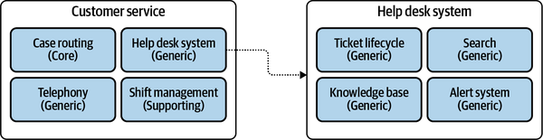
Figure 1-4. Distilling the help desk system subdomain, revealing generic inner components
Another important question to consider when identifying the subdomains is whether we need all of them.
Focus on the essentials
Subdomains are a tool that alleviates the process of making
When looking for subdomains, it’s important to identify business functions that are not related to software, acknowledge them as such, and focus on aspects of the business that are relevant to the software system you are working on.
Domain Analysis Examples
Disclaimer: of course, we cannot identify all the subdomains involved in each business domain by reading such a short description. That said, it is enough to train you to identify and categorize the available subdomains.
Gigmaster
Gigmaster’s users are conscious of their privacy. Hence, all users’ personal information is encrypted. Moreover, to ensure that users’ guilty pleasures won’t leak out under any circumstances, the company’s recommendation algorithm works exclusively on anonymized data.
To improve the app’s recommendations, a new module was implemented. It allows users to log gigs they attended in the past, even if the tickets weren’t purchased through Gigmaster.
Business domain and subdomains
Gigmaster’s business domain is ticket sales. That’s the service it provides to its customers.
Core subdomains
Gigmaster’s main competitive advantage is its recommendation engine. The company also takes its users’ privacy seriously and works only on anonymized data. Finally, although not mentioned explicitly, we can infer that the mobile app’s user experience is crucial as well. As such, Gigmaster’s core subdomains are:
-
Recommendation engine
-
Data anonymization
-
Mobile app
Generic subdomains
We can identify and infer the following generic subdomains:
-
Encryption, for encrypting all data
-
Accounting, since the company is in the sales business
-
Clearing, for charging its customers
-
Authentication and authorization, for identifying its users
Supporting subdomains
Finally, the following are the supporting subdomains. Here the business logic is simple and resembles ETL processes or CRUD interfaces:
-
Integration with music streaming services
-
Integration with social networks
-
Attended-gigs module
Design decisions
Knowing the subdomains at play and the differences between their types, we can already make several strategic design decisions:
-
The recommendation engine, data anonymization, and mobile app have to be implemented in-house using the most advanced engineering tools and techniques. These modules are going to change the most often.
-
Off-the-shelf or open source solutions should be used for data encryption, accounting, clearing, and authentication.
- Integration with streaming services and social networks, as well as the module for attended gigs, can be outsourced.
BusVNext
A BusVNext customer can order a ride through the mobile app. At the scheduled departure time, a nearby bus’s route will be adjusted on the fly to pick up the customer at the specified departure time.
From time to time, BusVNext issues special discounts, both to attract new customers and to level the demand for rides over peak and off-peak hours.
Business domain and subdomains
BusVNext provides optimized bus rides to its customers. The business domain is public transportation.
Core subdomains
BusVNext’s primary competitive advantage is its routing algorithm that takes a stab at solving a complex problem (“travelling salesman”) while prioritizing different business goals: for example, decreasing pickup times, even if it will increase overall ride lengths.
We also saw that the rides data is continuously analyzed for new insights into customers’ behaviors. These insights allow the company to increase its profits by optimizing the routing algorithm. Finally, BusVNext’s applications for its customers and its drivers have to be easy to use and provide a convenient user interface.
Managing a fleet is not trivial. Buses may experience technical issues or require maintenance. Ignoring these may result in financial losses and a reduced level of service.
Hence, BusVNext’s core subdomains are:
-
Routing
-
Analysis
-
Mobile app user experience
-
Fleet management
Generic subdomains
The routing algorithm also uses traffic data and alerts provided by third-party companies—a generic subdomain. Moreover, BusVNext accepts payments from its customers, so it has to implement accounting and clearing functionalities. BusVNext’s generic subdomains are:
-
Traffic conditions
-
Accounting
-
Billing
-
Authorization
Supporting subdomains
The module for managing promos and discounts supports the company’s core business. That said, it’s not a core subdomain by itself. Its management interface resembles a simple CRUD interface for managing active coupon codes. Therefore, this is a typical supporting subdomain.
Design decisions
Knowing the subdomains at play and the differences between their types, we can already make a number of strategic design decisions:
-
The routing algorithm, data analysis, fleet management, and app usability have to be implemented in-house using the most elaborate technical tools and patterns.
-
Implementation of the promotions management module can be outsourced.
-
Identifying traffic conditions, authorizing users, and managing financial records and transactions can be offloaded to external service providers.
Who Are the Domain Experts?
Now that we have a clear understanding of business domains and subdomains,
The domain experts are neither the analysts gathering the requirements nor the engineers designing the system. Domain experts represent the business. They are the people who identified the business problem in the first place and from whom all business knowledge originates. Systems analysts and engineers are transforming their mental models of the business domain into software requirements and source code.
As a rule of thumb, domain experts are either the people coming up with requirements or the software’s end users. The software is supposed to solve their problems.
The domain experts’ expertise can have different scopes. Some subject matter experts will have a detailed understanding of how the entire business domain operates, while others will specialize in particular subdomains. For example, in an online advertising agency, the domain experts would be campaign managers, media buyers, analysts, and other business stakeholders.
Conclusion
In this chapter, we covered domain-driven design tools for making sense of a company’s business activity. As you’ve seen, it all starts with the business domain: the area the business operates in and the service it provides to its clients.
You also learned about the different building blocks required to achieve success in a business domain and differentiate the company from its competitors:
- Core subdomains
- The interesting problems. These are the activities the company is performing differently from its competitors and from which it gains its competitive advantage.
- Generic subdomains
- The solved problems. These are the things all companies are doing in the same way. There is no room or need for innovation here; rather than creating in-house implementations, it’s more cost-effective to use existing solutions.
- Supporting subdomains
- The problems with obvious solutions. These are the activities the company likely has to implement in-house, but that do not provide any competitive advantage.
Finally, you learned that domain experts are the business’s subject matter experts. They have in-depth knowledge of the company’s business domain or one or more of its subdomains and are critical to a project’s success.
Exercises
-
Which of the subdomains provide(s) no competitive advantage?
-
Core
-
Generic
-
Supporting
-
B and C
-
-
For which subdomain might all competitors use the same solutions?
-
Core.
-
Generic.
-
Supporting.
-
None of the above. The company should always differentiate itself from its competitors.
-
-
Which subdomain is expected to change the most often?
-
Core.
-
Generic.
-
Supporting.
-
There is no difference in volatility of the different subdomain types.
-
-
What is WolfDesk’s business domain?
-
What is/are WolfDesk’s core subdomain(s)?
-
What is/are WolfDesk’s supporting subdomain(s)?
-
What is/are WolfDesk’s generic subdomain(s)?
Chapter 2. Discovering Domain Knowledge
It’s developers’ (mis)understanding, not domain experts’ knowledge, that gets released in production.
Alberto Brandolini
In the previous chapter, we started exploring business domains. You learned how to identify a company’s business domains, or areas of activity, and analyze its strategy to compete in them; that is, its business subdomains’ boundaries and types.
This chapter continues the topic of business domain analysis but in a different dimension: depth. It focuses on what happens inside a subdomain: its business function and logic. You will learn the domain-driven design tool for effective communication and knowledge sharing: the ubiquitous language. Here we will use it to learn the intricacies of business domains. Later in the book we will use it to model and implement their business logic in software.
Business Problems
Subdomains are finer-grained problem domains whose goal
Knowledge Discovery
To be effective, the software has to mimic the
Communication
It’s safe to say that almost all software projects require the collaboration of stakeholders in different roles: domain experts, product owners, engineers, UI and UX designers, project managers, testers, analysts, and others. As in any collaborative effort, the outcome depends on how well all those parties can work together. For example, do all stakeholders agree on what problem is being solved? What about the solution they are building—do they hold any conflicting assumptions about its functional and nonfunctional requirements? Agreement and alignment on all project-related matters are essential to a project’s success.
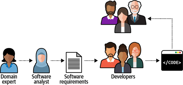
Figure 2-1. Knowledge sharing flow in a software project
During the traditional software development lifecycle, the domain knowledge is “translated” into an
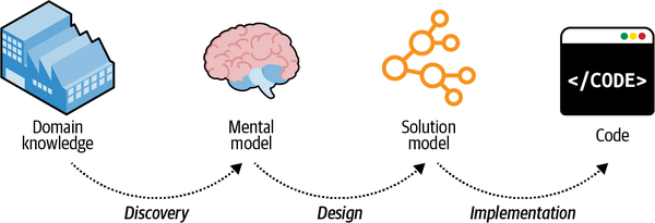
Figure 2-2. Model transformations
Such a software development process resembles the children’s game Telephone:3 the message, or domain knowledge, often becomes distorted. The information leads to software engineers implementing the wrong solution, or the right solution but to the wrong problems. In either case, the outcome is the same: a failed software project.
Domain-driven design proposes a better way to get the knowledge from domain experts to software engineers: by using a ubiquitous language.
What Is a Ubiquitous Language?
Although this notion is borderline common sense, as Voltaire said, “common sense is not so common.” The traditional software development lifecycle implies the following translations:
-
Domain knowledge into an analysis model
-
Analysis model into requirements
-
Requirements into system design
-
System design into source code
Instead of continuously translating domain knowledge, domain-driven design calls for cultivating a single language for describing the business domain: the ubiquitous language.
All project-related stakeholders—software engineers, product owners, domain experts, UI/UX designers—should use the ubiquitous language when describing the business domain. Most importantly, domain experts must be comfortable using the ubiquitous language when reasoning about the business domain; this language will represent both the business domain and the domain experts’ mental models.
Only through the continuous use of the ubiquitous language and its terms can a shared understanding among all of the project’s stakeholders be cultivated.
Language of the Business
It’s crucial to emphasize that the ubiquitous language is the language of the business. As such, it should consist of business domain–related terms only. No technical jargon! Teaching business domain experts about singletons and abstract factories is not your goal. The ubiquitous language aims to frame the domain experts’ understanding and mental models of the business domain in terms that are easy to understand.
Scenarios
Let’s say we are working on an advertising campaign management system. Consider the following statements:
-
An advertising campaign can display different creative materials.
-
A campaign can be published only if at least one of its placements is active.
-
Sales commissions are accounted for after transactions are approved.
All of these statements are formulated in the language of the business. That is, they reflect the domain experts’ view of the business domain.
On the other hand, the following statements are strictly technical and thus do not fit the notion of the ubiquitous language:
-
The advertisement iframe displays an HTML file.
-
A campaign can be published only if it has at least one associated record in the active-placements table.
-
Sales commissions are based on correlated records from the transactions and approved-sales tables.
These latter statements are purely technical and will be unclear to domain experts. Suppose engineers are only familiar with this technical, solution-oriented view of the business domain. In that case, they won’t be able to completely understand the business logic or why it operates the way it does, which will limit their ability to model and implement an effective solution.
Consistency
The ubiquitous language must be precise and consistent. It should eliminate the need for assumptions and should make the business domain’s logic explicit.
Since ambiguity hinders communication, each term of the ubiquitous language should have one and only one meaning. Let’s look at a few examples of unclear terminology and how it can be improved.
Ambiguous terms
Let’s say that in some business domain, the term policy has multiple meanings: it can mean a regulatory rule or an insurance contract. The exact meaning can be worked out in human-to-human interaction, depending on the context. Software, however, doesn’t cope well with ambiguity, and it can be cumbersome and challenging to model the “policy” entity in code.
Ubiquitous language demands a single meaning for each term, so “policy” should be modeled explicitly using the two terms regulatory rule and insurance contract.
Synonymous terms
Two terms cannot be used interchangeably in a ubiquitous language. For example, many systems use the term user. However, a careful examination of the domain experts’ lingo may reveal that user and other terms are used interchangeably: for example, user, visitor, administrator, account, etc.
Synonymous terms can seem harmless at first. However, in most cases, they denote different concepts. In this example, both visitor and account technically refer to the system’s users; however, in most systems, unregistered and registered users represent different roles and have different behaviors. For example, the “visitors” data is used mainly for analysis purposes, whereas “accounts” actually uses the system and its functionality.
Model of the Business Domain
Now let’s look at the ubiquitous language from a different perspective: modeling.
What Is a Model?
A model is a simplified representation of a thing orphenomenon that intentionally emphasizes certain aspects while ignoring others. Abstraction with a specific use in mind.Rebecca Wirfs-Brock
A model is not a copy of the real world but a human construct that helps us make sense of real-world systems.
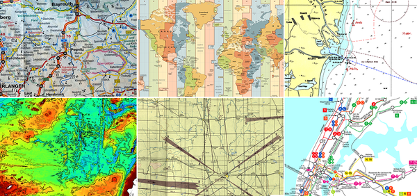
Figure 2-3. Different types of maps displaying different models of the earth: roads, time zones, nautical navigation, terrain, aeronautical navigation, and subway routes.
None of these maps represents all the details of our planet. Instead, each map contains just enough data to support its particular purpose: the problem it is supposed to solve.
Effective Modeling
All models have a purpose, and an effective model contains only the details
Modeling the Business Domain
When cultivating a ubiquitous language, we are effectively
Effective communication between engineering teams and domain experts is vital. The importance of this communication grows with the complexity of the business domain. The more complex the business domain is, the harder it is to model and implement its business logic in code. Even a slight misunderstanding of a complicated business domain, or its underlying principles, will inadvertently lead to an implementation prone to severe bugs. The only reliable way to verify a business domain’s understanding is to converse with domain experts and do it in the language they understand: the language of the business.
Continuous Effort
All stakeholders should consistently use the ubiquitous language in all project-related communications to spread knowledge about and foster a shared understanding of the business domain. The language should be continuously reinforced throughout the project: requirements, tests, documentation, and even the source code itself should use this language.
Most importantly, cultivation of a ubiquitous language is an ongoing process. It should be constantly validated and evolved. Everyday use of the language will, over time, reveal deeper insights into the business domain. When such breakthroughs happen, the ubiquitous language must evolve to keep pace with the newly acquired domain knowledge.
Tools
It’s important to make glossary maintenance a shared effort. When a ubiquitous language is changed, all team members should be encouraged to go ahead and update the glossary. That’s contrary to a centralized approach, in which only team leaders or architects are in charge of maintaining the glossary.
Scenario:Notify the agent about a new support caseGivenVincent Jules submits a new support case saying:"""I need help configuring AWS Infinidash"""Whenthe ticket is assigned to Mr. WolfThenthe agent receives a notification about the new ticket
Managing a Gherkin-based test suite can be challenging at times, especially at the early stages of a project. However, it is definitely worth it for complex business domains.
Finally, there are even static code analysis tools that can verify the usage of a ubiquitous language’s terms. A notable example for such a tool is NDepend.
While these tools are useful, they are secondary to the actual use of a ubiquitous language in day-to-day interactions. Use the tools to support the management of the ubiquitous language, but don’t expect the documentation to replace the actual usage.
As the Agile Manifesto says, “Individuals and interactions over processes and tools.” Challenges
In theory, cultivating a ubiquitous language sounds like a
simple, straightforward process. In practice, it isn’t. The only reliable way to gather domain knowledge is to converse with domain experts. Quite often, the most important knowledge is tacit. It’s not documented or codified but resides only in the minds of domain experts. The only way to access it is to ask questions. As you gain experience in this practice, you will notice that frequently, this process involves not merely discovering knowledge that is already there, but rather co-creating the model in tandem with domain experts. There may be ambiguities and even white spots in domain experts’ own understanding of the business domain; for example, defining only the “happy path” scenarios but not considering edge cases that challenge the accepted assumptions. Furthermore, you may encounter business domain concepts that lack explicit definitions. Asking questions about the nature of the business domain often makes such implicit conflicts and white spots explicit. This is especially common for core subdomains. In such a case, the learning process is mutual—you are helping the domain experts better understand their field.
When introducing domain-driven design practices to a brownfield project, you will notice that there is already a formed language for describing the business domain, and that the stakeholders use it. However, since DDD principles do not drive that language, it won’t necessarily reflect the business domain effectively. For example, it may use technical terms, such as database table names. Changing a language that is already being used in an organization is not easy. The essential tool in such a situation is patience. You need to make sure the correct language is used where it’s easy to control it: in the documentation and source code.
Finally, the question about the ubiquitous language that I am asked often at conferences is what language should we use if the company is not in an English-speaking country. My advice is to at least use English nouns for naming the business domain’s entities. This will alleviate using the same terminology in code. Conclusion
Effective communication and knowledge sharing are crucial for a successful software project. Software engineers have to understand the business domain in order to design and build a software solution.
Domain-driven design’s ubiquitous language is an effective tool for bridging the knowledge gap between domain experts and software engineers. It fosters communication and knowledge sharing by cultivating a shared language that can be used by all the stakeholders throughout the project: in conversations, documentation, tests, diagrams, source code, and so on.
To ensure effective communication, the ubiquitous language has to eliminate ambiguities and implicit assumptions. All of a language’s terms have to be consistent—no ambiguous terms and no synonymous terms.
Cultivating a ubiquitous language is a continuous process. As the project evolves, more domain knowledge will be discovered. It’s important for such insights to be reflected in the ubiquitous language.
Tools such as wiki-based glossaries and Gherkin tests can greatly alleviate the process of documenting and maintaining a ubiquitous language. However, the main prerequisite for an effective ubiquitous language is usage: the language has to be used consistently in all project-related communications.
Exercises
-
Who should be able to contribute to the definition of a ubiquitous language?
-
Domain experts
-
Software engineers
-
End users
-
All of the project’s stakeholders
-
Where should a ubiquitous language be used?
-
In-person conversations
-
Documentation
-
Code
-
All of the above
- Please review the description of the fictional WolfDesk company in the Preface. What business domain terminology can you spot in the description?
-
Consider a software project you are working on at the moment or worked on in the past:
-
Try to come up with concepts of the business domain that you could use in conversations with domain experts.
-
Try to identify examples of inconsistent terms: business domain concepts that have either different meanings or identical concepts represented by different terms.
-
Have you encountered software development inefficiencies that resulted from poor communication?
-
Assume you are working on a project and you notice that domain experts from different organizational units use the same term, for example, policy, to describe unrelated concepts of the business domain.
The resultant ubiquitous language is based on domain experts’ mental models but fails to fulfill the requirement of a term having a single meaning.
Before you continue to the next chapter, how would you address such a conundrum?
1 Brandolini, Alberto. (n.d.). Introducing EventStorming. Leanpub.
2 Sudhakar, Goparaju Purna. (2012). “A Model of Critical Success Factors for Software Projects.” Journal of Enterprise Information Management, 25(6), 537–558.
3 Players form a line, and the first player comes up with a message and whispers it into the ear of the second player. The second player repeats the message to the third player, and so on. The last player announces the message they heard to the entire group. The first player then compares the original message with the final version. Although the objective is to communicate the same message, it usually gets garbled and the last player receives a message that is significantly different from the original one.
4 Edsger W. Dijkstra, “The Humble Programmer”.
5 But please don’t fall into the trap of thinking that domain experts will write Gherkin tests.
Chapter 3. Managing Domain Complexity
As you saw in the previous chapter, to ensure a project’s success
Inconsistent Models
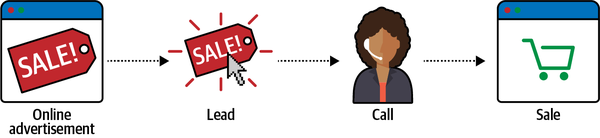
Figure 3-1. Example business domain: telemarketing company
An examination of the domain experts’ language reveals a peculiar observation. The term lead has different meanings in the marketing and sales departments:
- Marketing department
- For the marketing people, a lead represents a notification that somebody is interested in one of the products. The event of receiving the prospective customer’s contact details is considered a lead.
- Sales department
- In the context of the sales department, a lead is a much more complex entity. It represents the entire lifecycle of the sales process. It’s not a mere event, but a long-running process.
How do we formulate a ubiquitous language in the case of this telemarketing company?
On the one hand, we know the ubiquitous language has to be consistent—each term should have one meaning. On the other hand, we know the ubiquitous language has to reflect the domain experts’ mental models. In this case, the mental model of the “lead” is inconsistent among the domain experts in the sales and marketing departments.
This ambiguity doesn’t present that much of a challenge in person-to-person communications. Indeed, communication can be more challenging among people from different departments, but it’s easy enough for humans to infer the exact meaning from the interaction’s context.
However, it is more difficult to represent such a divergent model of the business domain in software. Source code doesn’t cope well with ambiguity. If we were to bring the sales department’s complicated model into marketing, it would introduce complexity where it’s not needed— far more detail and behavior than marketing people need for optimizing advertising campaigns. But if we were to try to simplify the sales model according to the marketing world view, it wouldn’t fit the sales subdomain’s needs, because it’s too simplistic for managing and optimizing the sales process. We’d have an overengineered solution in the first case and an under-engineered one in the second.
How do we solve this catch-22?
The traditional solution to this problem is to design a single model that can be used for all kinds of problems. Such models result in enormous entity relationship diagrams (ERDs) spanning whole office walls. Is Figure 3-2 an effective model?
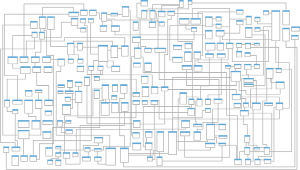
Figure 3-2. Enterprise-wide entity relationship diagram
As the saying goes, “jack of all trades, master of none.” Such models are supposed to be suitable for everything but eventually are effective for nothing. No matter what you do, you are always facing complexity: the complexity of filtering out extraneous details, the complexity of finding what you do need, and most importantly, the complexity of keeping the data in a consistent state.
Another solution would be to prefix the problematic term with a definition of the context: “marketing lead” and “sales lead.” That would allow the implementation of the two models in code. However, this approach has two main disadvantages. First, it induces cognitive load. When should each model be used? The closer the implementations of the conflicting models are, the easier it is to make a mistake. Second, the implementation of the model won’t be aligned with the ubiquitous language. No one would use the prefixes in conversations. People don’t need this extra information; they can rely on the conversation’s context.
Let’s turn to the domain-driven design pattern for tackling such scenarios: the bounded context pattern.
What Is a Bounded Context?
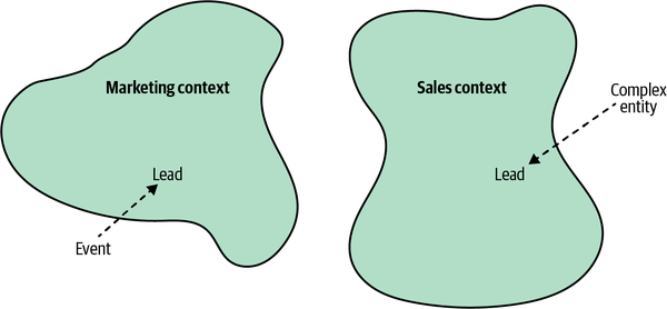
Figure 3-3. Tackling inconsistencies in the ubiquitous language by splitting it into bounded contexts
In a sense, terminology conflicts and implicit contexts are an inherent part of any decent-sized business. With the bounded context pattern, the contexts are modeled as an explicit and integral part of the business domain.
Model Boundaries
As we discussed in the previous chapter, a model is not a
Let’s go back to the example of maps as models. We saw that each map has its specific context—aerial, nautical, terrain, subway, and so on. A map is useful and consistent only within the scope of its specific purpose.
Just as a subway map is useless for nautical navigation, a ubiquitous language in one bounded context can be completely irrelevant to the scope of another bounded context. Bounded contexts define the applicability of a ubiquitous language and of the model it represents. They allow defining distinct models according to different problem domains. In other words, bounded contexts are the consistency boundaries of ubiquitous languages. A language’s terminology, principles, and business rules are only consistent inside its bounded context.
Ubiquitous Language Refined
Instead, a ubiquitous language is ubiquitous only in the boundaries of its bounded context. The language is focused on describing only the model that is encompassed by the bounded context. As a model cannot exist without a problem it is supposed to address, a ubiquitous language cannot be defined or used without an explicit context of its applicability.
Scope of a Bounded Context
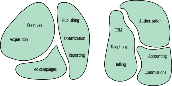
Figure 3-4. Smaller bounded contexts
Defining the scope of a ubiquitous language—its bounded context—is a strategic design decision.
A bounded context’s size, by itself, is not a deciding factor. Models shouldn’t necessarily be big or small. Models need to be useful. The wider the boundary of the ubiquitous language is, the harder it is to keep it consistent. It may be beneficial to divide a large ubiquitous language into smaller, more manageable problem domains, but striving for small bounded contexts can backfire too. The smaller they are, the more integration overhead the design induces.
Hence, the decision for how big your bounded contexts should depend on the specific problem domain. Sometimes, using a wide boundary will be clearer, while at other times, decomposing it further will make more sense.
The reasons for extracting finer-grained bounded contexts out of a larger one include constituting new software engineering teams or addressing some of the system’s nonfunctional requirements; for example, when you need to separate the development lifecycles of some of the components originally residing in a single bounded context. Another common reason for extracting one functionality is the ability to scale it independently from the rest of the bounded context’s functionalities.
We’ll discuss the topic of continuously optimizing the bounded contexts’ boundaries further in Chapters 8 and 10
Bounded Contexts Versus Subdomains
Subdomains
To comprehend a company’s business strategy, we have to analyze its business domain. According to domain-driven design methodology, the analysis phase involves identifying the different subdomains (core, supporting, and generic). That’s how the organization works and plans its competitive strategy.
Bounded Contexts
Bounded contexts, on the other hand, are designed. Choosing models’ boundaries is a strategic design decision. We decide how to divide the business domain into smaller, manageable problem domains.
The Interplay Between Subdomains and Bounded Contexts
Theoretically, though impractically, a single model could span the entire business domain.
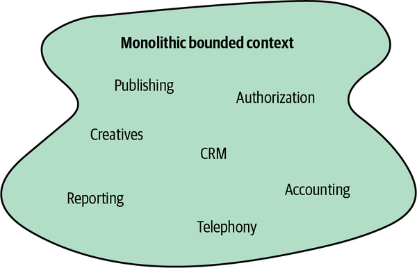
Figure 3-5. Monolithic bounded context
When conflicting models arise, we can follow the domain experts’ mental models and decompose the systems into bounded contexts, as shown in Figure 3-6.
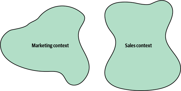
Figure 3-6. Bounded contexts driven by the consistency of the ubiquitous language
If the models are still large and hard to maintain, we can decompose them into even smaller bounded contexts; for example, by having a bounded context for each subdomain, as shown in Figure 3-7.

Figure 3-7. Bounded contexts aligned with subdomains’ boundaries
Either way, this is a design decision. We design those boundaries as a part of the solution.
Having a one-to-one relationship between bounded contexts and subdomains can be perfectly reasonable in some scenarios. In others, however, different decomposition strategies can be more suitable.
It’s crucial to remember that subdomains are discovered and bounded contexts are designed.1 The subdomains are defined by the business strategy. However, we can design the software solution and its bounded contexts to address the specific project’s context and constraints.
Finally, as you learned in Chapter 1, a model is intended to solve a specific problem. In some cases, it can be beneficial to use multiple models of the same concept simultaneously to solve different problems. As different types of maps provide different types of information about our planet, it may be reasonable to use different models of the same subdomain to solve different problems. Limiting the design to one-to-one relationships between bounded contexts would inhibit this flexibility and force us to use a single model of a subdomain in its bounded context.
Boundaries
Architectural design is system design. System design is contextual design—it is inherently about boundaries (what’s in, what’s out, what spans, what moves between), and about trade-offs. It reshapes what is outside, just as it shapes what is inside.2
The bounded context pattern is the domain-driven design tool for defining physical and ownership boundaries.
Physical Boundaries
Bounded contexts serve not only as model boundaries but also
Clear physical boundaries between bounded contexts allow us to implement each bounded context with the technology stack that best fits its needs.
Ownership Boundaries
A bounded context should be implemented, evolved, and maintained by one team only. No two teams can work on the same bounded context. This segregation eliminates implicit assumptions that teams might make about one another’s models. Instead, they have to define communication protocols for integrating their models and systems explicitly.
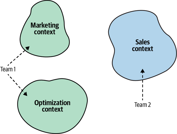
Figure 3-8. Team 1 working on the Marketing and Optimization bounded contexts, while Team 2 works on the Sales bounded context
Bounded Contexts in Real Life
In one of my domain driven-design classes, a participant once
Indeed, bounded contexts are not as evident as business domains and subdomains, but they are there, as domain experts’ mental models are. You just have to be conscious about how domain experts think about the different business entities and processes.
I want to close this chapter by discussing examples demonstrating that not only are bounded contexts there when we are modeling business domains in software, but the notion of using different models in different contexts is widespread in life in general.
Semantic Domains
A rather peculiar example of different semantic domains is the meaning of the word tomato.
According to the botanic definition, a fruit is the plant’s way of spreading its seeds. A fruit should grow from the plant’s flower, and bear at least one seed. A vegetable, on the other hand, is a general term encompassing all other edible parts of a plant: roots, stems, and leaves. Based on this definition, the tomato is a fruit.
That definition, however, is of little use in the context of the culinary arts. In this context, fruits and vegetables are defined based on their flavor profiles. A fruit has a soft texture, is either sweet or sour, and can be enjoyed in its raw form, whereas a vegetable has a tougher texture, tastes blander, and often requires cooking. According to this definition, the tomato is a vegetable.
Hence, in the bounded context of botany, the tomato is a fruit, while in the bounded context of the culinary arts, it’s a vegetable. But that’s not all.
In 1883 the United States established a 10% tax on imported vegetables, but not fruits. The botanic definition of the tomato as a fruit allowed the importation of tomatoes to the United States without paying the import tax. To close the loophole, in 1893 the United States Supreme Court made the decision to classify the tomato as a vegetable. Therefore, in the bounded context of taxation, the tomato is a vegetable.
Furthermore, as my friend Romeu Moura says, in the bounded context of theatrical performances, the tomato is a feedback mechanism.
Science
As historian Yuval Noah Harari puts it, “Scientists generally agree
This notion can be demonstrated by the different models of gravity introduced by Sir Isaac Newton and Albert Einstein. According to Newton’s laws of motion, space and time are absolute. They are the stage on which the motion of objects happens. In Einstein’s theory of relativity, space and time are no longer absolute but different for different observers.
Even though the two models can be seen as contradictory, both are useful in their suitable (bounded) contexts.
Buying a Refrigerator

Figure 3-9. A piece of cardboard
Is it just a piece of cardboard? No, it’s a model. It’s a model of the Siemens KG86NAI31L refrigerator. If you look it up, you may say the piece of cardboard doesn’t look anything like that fridge. It has no doors, and even its color is different.
Although that’s true, it’s not relevant. As we’ve discussed, a model is not supposed to copy a real-world entity. Instead, it should have a purpose—a problem it is supposed to solve. Hence, the correct question to ask about the cardboard is, what problem does this model solve?
In our apartment, we do not have a standard entry into the kitchen. The cardboard was cut precisely to the size of the fridge’s width and depth. The problem it solves is checking whether the refrigerator can fit through the kitchen door (see Figure 3-10).

Figure 3-10. The cardboard model in the kitchen doorway
Despite the cardboard not looking anything like the fridge, it proved extremely useful when we had to decide whether to buy this model or opt for a smaller one. Again, all models are wrong, but some are useful. Building a 3D model of the fridge would definitely be a fun project. But would it solve the problem any more efficiently than the cardboard? No. If the cardboard fits, the 3D model would fit as well, and vice versa. In software engineering terms, building a 3D model of the fridge would be gross overengineering.
But what about the refrigerator’s height? What if the base fits, but it’s too tall to fit in the doorway? Would that justify gluing together a 3D model of the fridge? No. The problem can be solved much more quickly and easily by using a simple tape measure to check the doorway’s height. What is a tape measure in this case? Another simple model.
So, we ended up with two models of the same fridge. Using two models, each optimized for its specific task, reflects the DDD approach to modeling business domains. Each model has its strict bounded context: the cardboard verifying that the refrigerator’s base can make it through the kitchen’s entry, and the tape measure verifying that it’s not too tall. A model should omit the extraneous information irrelevant to the task at hand. Also, there’s no need to design a complex jack-of-all-trades model if multiple, much simpler models can effectively solve each problem individually.
A few days after I published this story on Twitter, I received a reply saying that instead of fiddling with cardboard, I could have just used a mobile phone with a LiDAR scanner and an augmented reality (AR) application. Let’s analyze this suggestion from the domain-driven design perspective.
The author of the comment says this is a problem that others have already solved, and the solution is readily available. Needless to say, both the scanning technology and the AR application are complex. In DDD lingo, that makes the problem of checking whether the refrigerator will fit through the doorway a generic subdomain.
Conclusion
Whenever we stumble upon an inherent conflict in the domain experts’ mental models, we have to decompose the ubiquitous language into multiple bounded contexts. A ubiquitous language should be consistent within the scope of its bounded context. However, across bounded contexts, the same terms can have different meanings.
While subdomains are discovered, bounded contexts are designed. The division of the domain into bounded contexts is a strategic design decision.
A bounded context and its ubiquitous language can be implemented and maintained by one team. No two teams can share the work on the same bounded context. However, one team can work on multiple bounded contexts.
Bounded contexts decompose a system into physical components—services, subsystems, and so on. Each bounded context’s lifecycle is decoupled from the rest. Each bounded context can evolve independently from the rest of the system. However, the bounded contexts have to work together to form a system. Some of the changes will inadvertently affect another bounded context. In the next chapter, we’ll talk about the different patterns for integrating bounded contexts that can be used to protect them from cascading changes.
Exercises
-
What is the difference between subdomains and bounded contexts?
-
Subdomains are designed, while bounded contexts are discovered.
-
Bounded contexts are designed, while subdomains are discovered.
-
Bounded contexts and subdomains are essentially the same.
-
None of the above is true.
-
-
A bounded context is a boundary of:
-
A model
-
A lifecycle
-
Ownership
-
All of the above
-
-
Which of the following is true regarding the size of a bounded context?
The smaller the bounded context is, the more flexible the system is.
-
Bounded contexts should always be aligned with the boundaries of subdomains.
-
The wider the bounded context is, the better.
-
It depends.
-
-
Which of the following is true regarding team ownership of a bounded context?
-
Multiple teams can work on the same bounded context.
-
A single team can own multiple bounded contexts.
-
A bounded context can be owned by one team only.
-
B and C are correct.
-
-
Review the example of the WolfDesk company in the Preface and try to identify functionalities of the system that may require different models of a support ticket.
-
Try to find examples of real-life bounded contexts, in addition to those described in this chapter.
2 Bredemeyer Consulting, “What Is Software Architecture.” Retrieved September 22, 2021, https://www.bredemeyer.com/who.htm
Chapter 4. Integrating Bounded Contexts
Not only does the bounded context pattern protect the consistency of a ubiquitous language, it also enables modeling.
Moreover, models in different bounded contexts can be evolved and implemented independently. That said, bounded contexts themselves are not independent. Just as a system cannot be built out of independent components—the components have to interact with one another to achieve the system’s overarching goals—so, too, do the implementations in bounded contexts. Although they can evolve independently, they have to integrate with one another. As a result, there will always be touchpoints between bounded contexts. These are called contracts.
The need for contracts results from differences in bounded contexts’ models and languages. Since each contract affects more than one party, they need to be defined and coordinated. Also, by definition, two bounded contexts are using different ubiquitous languages. Which language will be used for integration purposes? These integration concerns should be evaluated and addressed by the solution’s design.
In this chapter, you will learn about domain-driven design patterns for defining relationships and integrations between bounded contexts. These patterns are driven by the nature of collaboration between teams working on bounded contexts. We will divide the patterns into three groups, each representing a type of team collaboration: cooperation, customer–supplier, and separate ways.
Cooperation
In the simplest case, these are bounded contexts implemented by a single team. This also applies to teams with dependent goals, where one team’s success depends on the success of the other, and vice versa. Again, the main criterion here is the quality of the teams’ communication and collaboration.
Let’s look at two DDD patterns suitable for cooperating teams: the partnership and shared kernel patterns.
Partnership
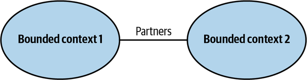
Figure 4-1. The partnership model
The coordination of integration here is two-way. No one team dictates the language that is used for defining the contracts. The teams can work out the differences and choose the most appropriate solution. Also, both sides cooperate in solving any integration issues that might come up. Neither team is interested in blocking the other one.
Well-established collaboration practices, high levels of commitment, and frequent synchronizations between teams are required for successful integration in this manner. From a technical perspective, continuous integration of the changes applied by both teams is needed to further minimize the integration feedback loop.
This pattern might not be a good fit for geographically distributed teams since it may present synchronization and communication challenges.
Shared Kernel
Despite bounded contexts being model boundaries, there still can be
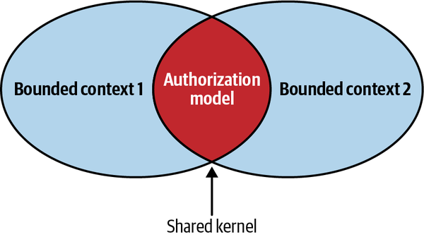
Figure 4-2. Shared kernel
Implementation
If the organization uses the mono-repository approach, these can be the same source files referenced by multiple bounded contexts. If using a shared repository is not possible, the shared kernel can be extracted into a dedicated project and referenced in the bounded contexts as a linked library. Either way, each change to the shared kernel must trigger integration tests for all the affected bounded contexts.
The continuous integration of changes is required because the shared kernel belongs to multiple bounded contexts. Not propagating shared kernel changes to all related bounded contexts leads to inconsistencies in a model: bounded contexts may rely on stale implementations of the shared kernel, leading to data corruption and/or runtime issues.
Customer–Supplier
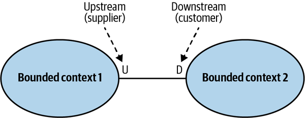
Figure 4-3. Customer–supplier relationship
Unlike in the cooperation case, both teams (upstream and downstream) can succeed independently.
This section will discuss three patterns addressing such power differences: the conformist, anticorruption layer, and open-host service patterns.
Conformist
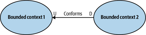
Figure 4-4. Conformist relationship
The downstream team’s decision to give up some of its autonomy can be justified in multiple ways. For example, the contract exposed by the upstream team may be an industry-standard, well-established model, or it may just be good enough for the downstream team’s needs.
The next pattern addresses the case in which a consumer is not willing to accept the supplier’s model.
Anticorruption Layer
As in the conformist pattern, the balance of power in this relationship
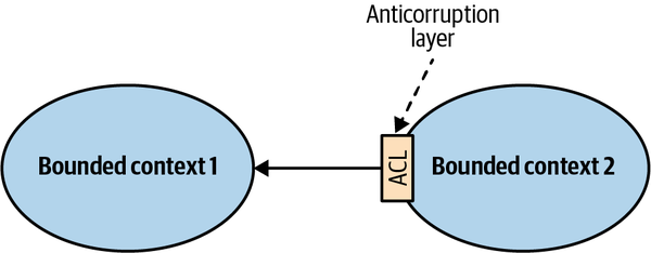
Figure 4-5. Integration through an anticorruption layer
The anticorruption layer pattern addresses scenarios in which it is not desirable or worth the effort to conform to the supplier’s model, such as the following:
- When the downstream bounded context contains a core subdomain
- A core subdomain’s model requires extra attention, and adhering to the supplier’s model might impede the modeling of the problem domain.
- When the upstream model is inefficient or inconvenient for the consumer’s needs
- If a bounded context conforms to a mess, it risks becoming a mess itself. That is often the case when integrating with legacy systems.
- When the supplier’s contract changes often
- The consumer wants to protect its model from frequent changes. With an anticorruption layer, the changes in the supplier’s model only affect the translation mechanism.
From a modeling perspective, the translation of the supplier’s model isolates the downstream consumer from foreign concepts that are not relevant to its bounded context. Hence, it simplifies the consumer’s ubiquitous language and model.
In Chapter 9, we will explore the different ways to implement an anticorruption layer.
Open-Host Service
This pattern addresses cases in which the power is skewed toward
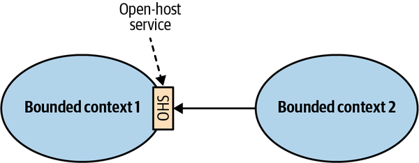
Figure 4-6. Integration through an open-host service
The supplier’s public interface is not intended to conform to its ubiquitous language.
In a sense, the open-host service pattern is a reversal of the anticorruption layer pattern: instead of the consumer, the supplier implements the translation of its internal model.
Decoupling the bounded context’s implementation and integration models gives the upstream bounded context the freedom to evolve its implementation without affecting the downstream contexts. Of course, that’s only possible if the modified implementation model can be translated into the published language the consumers are already using.
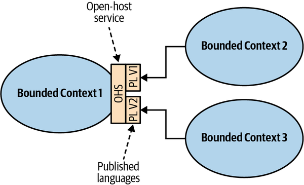
Figure 4-7. Open-host service exposing multiple versions of the published language
Separate Ways
Communication Issues
Generic Subdomains
Model Differences
Note
The separate ways pattern should be avoided when integrating core subdomains. Duplicating the implementation of such subdomains would defy the company’s strategy to implement them in the most effective and optimized way.
Context Map
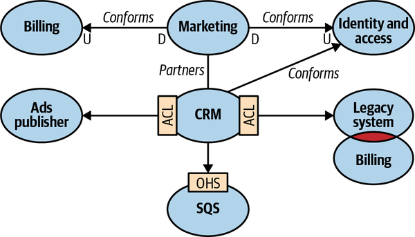
Figure 4-8. Context map
The context map is a visual representation of the system’s bounded contexts and the integrations between them. This visual notation gives valuable strategic insight on multiple levels:
- High-level design
- A context map provides an overview of the system’s components and the models they implement.
- Communication patterns
- A context map depicts the communication patterns amongteams—for example, which teams are collaborating and which prefer “less intimate” integration patterns, such as the anticorruption layer and separate ways patterns.
- Organizational issues
- A context map can give insight into organizational issues. For example, what does it mean if a certain upstream team’s downstream consumers all resort to implementing an anticorruption layer, or if all implementations of the separate ways pattern are concentrated around the same team?
Maintenance
Since the context map potentially contains information originating from the work of multiple teams, it’s best to define the maintenance of the context map as a shared effort: each team is responsible for updating its own integrations with other bounded contexts.
Limitations
It’s important to note that charting a context map can be a
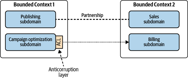
Figure 4-9. Complicated context map
Moreover, even if bounded contexts are limited to a single subdomain, there still can be multiple integration patterns at play—for example, if the subdomains’ modules require different integration strategies.
Conclusion
Bounded contexts are not independent. They have to interact with one another. The following patterns define different ways bounded contexts can be integrated:
- Partnership
- Bounded contexts are integrated in an ad hoc manner.
- Shared kernel
- Two or more bounded contexts are integrated by sharing a limited overlapping model that belongs to all participating bounded contexts.
- Conformist
- The consumer conforms to the service provider’s model.
- Anticorruption layer
- The consumer translates the service provider’s model into a model that fits the consumer’s needs.
- Open-host service
- The service provider implements a published language—a model optimized for its consumers’ needs.
- Separate ways
- It’s less expensive to duplicate particular functionality than to collaborate and integrate it.
The integrations among the bounded contexts can be plotted on a context map. This tool gives insight into the system’s high-level design, communication patterns, and organizational issues.
Exercises
-
Which integration pattern should never be used for a core subdomain?
-
Shared kernel
-
Open-host service
-
Anticorruption layer
-
Separate ways
-
-
Which downstream subdomain is more likely to implement an anticorruption layer?
-
Core subdomain
-
Supporting subdomain
-
Generic subdomain
-
B and C
-
-
Which upstream subdomain is more likely to implement an open-host service?
-
Core subdomain
-
Supporting subdomain
-
Generic subdomain
-
A and B
-
-
Which integration pattern, in a sense, violates bounded contexts’ ownership boundaries?
-
Partnership.
-
Shared kernel.
-
Separate ways.
-
No integration pattern should ever break the bounded contexts’ ownership boundaries.
-
Part II. Tactical Design
In Part I, we discussed the “what” and “why” of software: you learned to analyze business domains, identify subdomains and their strategic value, and turn the knowledge of business domains into the design of bounded contexts—software components implementing different models of the business domain.
In this part of the book, we will turn from strategy to tactics: the “how” of software design:
-
In Chapters 5 through 7, you will learn business logic implementation patterns that allow the code to speak the ubiquitous language of its bounded context. Chapter 5 introduces two patterns that accommodate a relatively simple business logic: transaction script and active record. Chapter 6 moves to more challenging cases and presents the domain model pattern: DDD’s way of implementing complex business logic. In Chapter 7, you will learn to expand the domain model pattern by modeling the dimension of time.
-
In Chapter 8, we will explore the different ways to organize a bounded context’s architecture: the layered architecture, ports & adapters, and CQRS patterns. You will learn the essence of each architectural pattern and in which cases each pattern should be used.
-
Chapter 9 will discuss technical concerns and implementation strategies for orchestrating the interactions among components of a system. You will learn patterns supporting the implementation of bounded context integration patterns, how to implement reliable publishing of messages, and patterns for defining complex, cross-component workflows.
Chapter 5. Implementing Simple Business Logic
Business logic is the most important part of software.
Transaction Script
Organizes business logic by procedures where each procedure handles a single request from the presentation.
Martin Fowler1
A system’s public interface can be seen as a collection of business transactions that consumers can execute, as shown in Figure 5-1. These transactions can retrieve information managed by the system, modify it, or both. The pattern organizes the system’s business logic based on procedures, where each procedure implements an operation that is executed by the system’s consumer via its public interface. In effect, the system’s public operations are used as encapsulation boundaries.
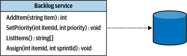
Figure 5-1. Transaction script interface
Implementation
Each procedure is implemented as a simple, straightforward procedural script.
The only requirement procedures have to fulfill is transactional behavior. Each operation should either succeed or fail but can never result in an invalid state. Even if execution of a transaction script fails at the most inconvenient moment, the system should remain consistent—either by rolling back any changes it has made up until the failure or by executing compensating actions. The transactional behavior is reflected in the pattern’s name: transaction script.
Here is an example of a transaction script that converts batches of JSON files into XML files:
DB.StartTransaction();varjob=DB.LoadNextJob();varjson=LoadFile(job.Source);varxml=ConvertJsonToXml(json);WriteFile(job.Destination,xml.ToString();DB.MarkJobAsCompleted(job);DB.Commit()
It’s Not That Easy!
When I introduce the transaction script pattern in my domain-driven design classes, my students often raise their eyebrows, and some even ask, “Is it worth our time? Aren’t we here for the more advanced patterns and techniques?”
Let’s take a look at three common, real-life examples of data corruption that results from failing to correctly implement a transaction script.
Lack of transactional behavior
A trivial example of failing to implement transactional behavior is to issue multiple updates without an overarching transaction. Consider the following method that updates a record in the Users table and inserts a record into the VisitsLog table:
01publicclassLogVisit02{03...0405publicvoidExecute(GuiduserId,DataTimevisitedOn)06{07_db.Execute("UPDATE Users SET last_visit=@p1 WHERE user_id=@p2",08visitedOn,userId);09_db.Execute(@"INSERT INTO VisitsLog(user_id, visit_date)10 VALUES(@p1, @p2)",userId,visitedOn);11}12}
If any issue occurs after the record in the Users table was updated (line 7) but before appending the log record on line 9 succeeds, the system will end up in an inconsistent state. The Users table will be updated but no corresponding record will be written to the VisitsLog table. The issue can be due to anything from a network outage to a database timeout or deadlock, or even a crash of the server executing the process.
This can be fixed by introducing a proper transaction encompassing both data changes:
publicclassLogVisit{...publicvoidExecute(GuiduserId,DataTimevisitedOn){try{_db.StartTransaction();_db.Execute(@"UPDATE Users SET last_visit=@p1WHERE user_id=@p2",visitedOn,userId);_db.Execute(@"INSERT INTO VisitsLog(user_id, visit_date)VALUES(@p1, @p2)",userId,visitedOn);_db.Commit();}catch{_db.Rollback();throw;}}}
The fix is easy to implement due to relational databases’ native support of transactions spanning multiple records. Things get more complicated when you have to issue multiple updates in a database that doesn’t support multirecord transactions, or when you are working with multiple storage mechanisms that are impossible to unite in a distributed transaction. Let’s see an example of the latter case.
Distributed transactions
In modern distributed systems, it’s a common practice to make changes to the data in a database and then notify other components of the system about the changes by publishing messages into a message bus. Consider that in the previous example, instead of logging a visit in a table, we have to publish it to a message bus:
01publicclassLogVisit02{03...0405publicvoidExecute(GuiduserId,DataTimevisitedOn)06{07_db.Execute("UPDATE Users SET last_visit=@p1 WHERE user_id=@p2",08visitedOn,userId);09_messageBus.Publish("VISITS_TOPIC",10new{UserId=userId,VisitDate=visitedOn});11}12}
As in the previous example, any failure occurring after line 7 but before line 9 succeeds will corrupt the system’s state. The Users table will be updated but the other components won’t be notified as publishing to the message bus has failed.
Let’s see a more intricate example of improper implementation of transactional behavior.
Implicit distributed transactions
Consider the following deceptively simple method:
publicclassLogVisit{...publicvoidExecute(GuiduserId){_db.Execute("UPDATE Users SET visits=visits+1 WHERE user_id=@p1",userId);}}
Instead of tracking the last visit date as in the previous examples, this method maintains a counter of visits for each user. Calling the method increases the corresponding counter’s value by 1. All the method does is update one value, in one table, residing in one database. Yet this is still a distributed transaction that can potentially lead to inconsistent state.
This example constitutes a distributed transaction because it communicates information to the databases and the external process that called the method, as demonstrated in Figure 5-2.
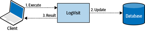
Figure 5-2. The LogVisit operation updating the data and notifying the caller of the operation’s success or failure
Although the execute method is of type void, that is, it doesn’t return any data, it still communicates whether the operation has succeeded or failed: if it failed, the caller will get an exception.
-
If
LogVisitis part of a REST service and there is a network outage; or -
If both
LogVisitand the caller are running in the same process, but the process fails before the caller gets to track successful execution of theLogVisitaction?
In both cases, the consumer will assume failure and try calling LogVisit again. Executing the LogVisit logic again will result in an incorrect increase of the counter’s value. Overall, it will be increased by 2 instead of 1. As in the previous two examples, the code fails to implement the transaction script pattern correctly, and inadvertently leads to corrupting the system’s state.
As in the previous example, there is no simple fix for this issue. It all depends on the business domain and its needs. In this specific example, one way to ensure transactional behavior is to make the operation idempotent: that is, leading to the same result even if the operation repeated multiple times.
For example, we can ask the consumer to pass the value of the counter. To supply the counter’s value, the caller will have to read the current value first, increase it locally, and then provide the updated value as a parameter. Even if the operation will be executed multiple times, it won’t change the end result:
publicclassLogVisit{...publicvoidExecute(GuiduserId,longvisits){_db.Execute("UPDATE Users SET visits = @p1 WHERE user_id=@p2",visits,userId);}}
Another way to address such an issue is to use optimistic concurrency control: prior to calling the LogVisit operation, the caller has read the counter’s current value and passed it to LogVisit as a parameter. LogVisit will update the counter’s value only if it equals the one initially read by the caller:
publicclassLogVisit{...publicvoidExecute(GuiduserId,longexpectedVisits){_db.Execute(@"UPDATE Users SET visits=visits+1WHERE user_id=@p1 and visits = @p2",userId,visits);}}
LogVisit with the same input parameters won’t change the data, as the WHERE...visits = @prm2 condition won’t be fulfilled.When to Use Transaction Script
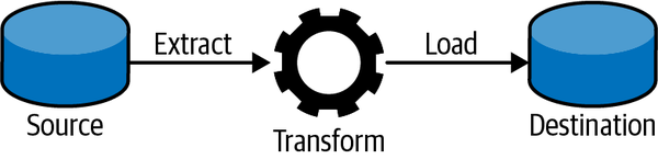
Figure 5-3. Extract-transform-load data flow
The transaction script pattern naturally fits supporting subdomains where, by definition, the business logic is simple. It can also be used as an adapter for integration with external systems—for example, generic subdomains, or as a part of an anticorruption layer (more on that in Chapter 9).
The main advantage of the transaction script pattern is its simplicity. It introduces minimal abstractions and minimizes the overhead both in runtime performance and in understanding the business logic. That said, this simplicity is also the pattern’s disadvantage. The more complex the business logic gets, the more it’s prone to duplicate business logic across transactions, and consequently, to result in inconsistent behavior—when the duplicated code goes out of sync. As a result, transaction script should never be used for core subdomains, as this pattern won’t cope with the high complexity of a core subdomain’s business logic.
This simplicity earned the transaction script a dubious reputation. Sometimes the pattern is even treated as an antipattern. After all, if complex business logic is implemented as a transaction script, sooner rather than later it’s going to turn into an unmaintainable, big ball of mud. It should be noted, however, that despite the simplicity, the transaction script pattern is ubiquitous in software development. All the business logic implementation patterns that we will discuss in this and the following chapters, in one way or another, are based on the transaction script pattern.
Active Record
An object that wraps a row in a database table or view, encapsulates the database access, and adds domain logic on that data.Martin Fowler2
Like the transaction script pattern, active record supports cases where the business logic is simple. Here, however, the business logic may operate on more complex data structures. For example, instead of flat records, we can have more complicated object trees and hierarchies, as shown in Figure 5-4.
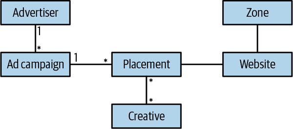
Figure 5-4. A more complicated data model with one-to-many and many-to-many relationships
Operating on such data structures via a simple transaction script would result in lots of repetitive code. The mapping of the data to an in-memory representation would be duplicated all over.
Implementation
Consequently, this pattern uses dedicated objects, known as active records,
publicclassCreateUser{...publicvoidExecute(userDetails){try{_db.StartTransaction();varuser=newUser();user.Name=userDetails.Name;user.=userDetails.;user.Save();_db.Commit();}catch{_db.Rollback();throw;}}}
The pattern’s goal is to encapsulate the complexity of mapping the in-memory object to the database’s schema. In addition to being responsible for persistence, the active record objects can contain business logic; for example, validating new values assigned to the fields, or even implementing business-related procedures that manipulate an object’s data. That said, the distinctive feature of an active record object is the separation of data structures and behavior (business logic). Usually, an active record’s fields have public getters and setters that allow external procedures to modify its state.
When to Use Active Record
Accordingly, as in the case of the transaction script pattern, the active record pattern lends itself to supporting subdomains, integration of external solutions for generic subdomains, or model transformation tasks. The difference between the patterns is that active record addresses the complexity of mapping complicated data structures to a database’s schema.
Note
Be Pragmatic
As always, there are no universal laws. It all depends on the business domain you are working in. It’s OK to “cut corners” where possible; just make sure you evaluate the risks and business implications.
Conclusion
In this chapter, we covered two patterns for implementing business logic:
- Transaction script
- This pattern organizes the system’s operations as simple, straightforward procedural scripts. The procedures ensure that each operation is transactional—either it succeeds or it fails. The transaction script pattern lends itself to supporting subdomains, with business logic resembling simple, ETL-like operations.
- Active record
- When the business logic is simple but operates on complicated data structures, you can implement those data structures as active records. An active record object is a data structure that provides simple CRUD data access methods.
The two patterns discussed in this chapter are oriented toward cases of rather simple business logic. In the next chapter, we will turn to more complex business logic and discuss how to tackle the complexity using the domain model pattern.
Exercises
-
Which of the discussed patterns should be used for implementing a core subdomain’s business logic?
-
Transaction script.
-
Active record.
-
Neither of these patterns can be used to implement a core subdomain.
-
Both can be used to implement a core subdomain.
-
-
Consider the following code:
publicvoidCreateTicket(TicketDatadata){varagent=FindLeastBusyAgent();agent.ActiveTickets=agent.ActiveTickets+1;agent.Save();varticket=newTicket();ticket.Id=Guid.New();ticket.Data=data;ticket.AssignedAgent=agent;ticket.Save();_alerts.Send(agent,"You have a new ticket!");}Assuming there is no high-level transaction mechanism, what potential data consistency issues can you spot here?
-
On receiving a new ticket, the assigned agent’s counter of active tickets can be increased by more than 1.
-
An agent’s counter of active tickets can be increased by 1 but the agent won’t get assigned any new tickets.
-
An agent can get a new ticket but won’t be notified about it.
-
All of the above issues are possible.
-
-
In the preceding code, there is at least one more possible edge case that can corrupt the system’s state. Can you spot it?
-
Going back to the example of WolfDesk in the book’s Preface, what parts of the system could potentially be implemented as a transaction script or an active record?
2 Fowler, M. (2002). Patterns of Enterprise Application Architecture. Boston: Addison-Wesley.
Chapter 6. Tackling Complex Business Logic
The previous chapter discussed two patterns addressing cases of relatively simple business logic: transaction script and active record. This chapter continues the topic of implementing business logic and introduces a pattern oriented for complicated business logic: the domain model pattern.
History
As with both the transaction script and active record patterns, the
In his book, Evans presents a set of patterns aimed at tightly relating the code to the underlying model of the business domain: aggregate, value objects, repositories, and others. These patterns closely follow where Fowler left off in his book and resemble an effective set of tools for implementing the domain model pattern.
The patterns that Evans introduced are often referred to as tactical domain-driven design. To eliminate the confusion of thinking that implementing domain-driven design necessarily entails the use of these patterns to implement business logic, I prefer to stick with Fowler’s original terminology. The pattern is “domain model,” and the aggregates and value objects are its building blocks.
Domain Model
Let’s assume we are implementing a help desk system. Consider the following excerpt from the requirements that describes the logic controlling the lifecycles of support tickets:
-
Customers open support tickets describing issues they are facing.
-
Both the customer and the support agent append messages, and all the correspondence is tracked by the support ticket.
-
Each ticket has a priority: low, medium, high, or urgent.
-
An agent should offer a solution within a set time limit (SLA) that is based on the ticket’s priority.
-
If the agent doesn’t reply within the SLA, the customer can escalate the ticket to the agent’s manager.
-
Escalation reduces the agent’s response time limit by 33%.
-
If the agent didn’t open an escalated ticket within 50% of the response time limit, it is automatically reassigned to a different agent.
-
Tickets are automatically closed if the customer doesn’t reply to the agent’s questions within seven days.
-
Escalated tickets cannot be closed automatically or by the agent, only by the customer or the agent’s manager.
-
A customer can reopen a closed ticket only if it was closed in the past seven days.
These requirements form an entangled net of dependencies among the different rules, all affecting the support ticket’s lifecycle management logic. This is not a CRUD data entry screen, as we discussed in the previous chapter. Attempting to implement this logic using active record objects will make it easy to duplicate the logic and corrupt the system’s state by misimplementing some of the business rules.
Implementation
All of these patterns share a common theme: they put the business logic first. Let’s see how the domain model addresses different design concerns.
Complexity
The domain’s business logic is already inherently complex, so the objects
Ubiquitous language
The emphasis on business logic instead of technical concerns makes
Building Blocks
Let’s look at the central domain model building blocks, or tactical patterns, offered by DDD: value objects, aggregates, and domain services.
Value object
classColor{int_red;int_green;int_blue;}
The composition of the values of the three fields red, green, and blue defines a color. Changing the value of one of the fields will result in a new color. No two colors can have the same values. Also, two instances of the same color must have the same values. Therefore, no explicit identification field is needed to identify colors.
ColorId field shown in red, green, and blue, but comparing the values of ColorId would not reflect that this is the same color. 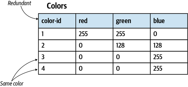
Figure 6-1. Redundant ColorId field, making it possible to have two rows with the same values
Ubiquitous language
Relying exclusively on the language’s standard library’s primitive
classPerson{privateint_id;privatestring_firstName;privatestring_lastName;privatestring_landlinePhone;privatestring_mobilePhone;privatestring_email;privateint_heightMetric;privatestring_countryCode;publicPerson(...){...}}staticvoidMain(string[]args){vardave=newPerson(id:30217,firstName:"Dave",lastName:"Ancelovici",landlinePhone:"023745001",mobilePhone:"0873712503",:"dave@learning-ddd.com",heightMetric:180,countryCode:"BG");}
In the preceding implementation of the Person class, most of the values are of type String and they are assigned based on convention. For example, the input to the landlinePhone should be a valid landline phone number, and the countryCode should be a valid, two-letter, uppercased country code. Of course, the system cannot trust the user to always supply correct values, and as a result, the class has to validate all input fields.
This approach presents multiple design risks. First, the validation logic tends to be duplicated. Second, it’s hard to enforce calling the validation logic before the values are used. It will become even more challenging in the future, when the codebase will be evolved by other engineers.
Compare the following alternative design of the same object, this time leveraging value objects:
classPerson{privatePersonId_id;privateName_name;privatePhoneNumber_landline;privatePhoneNumber_mobile;privateEmailAddress_email;privateHeight_height;privateCountryCode_country;publicPerson(...){...}}staticvoidMain(string[]args){vardave=newPerson(id:newPersonId(30217),name:newName("Dave","Ancelovici"),landline:PhoneNumber.Parse("023745001"),mobile:PhoneNumber.Parse("0873712503"),:.Parse("dave@learning-ddd.com"),height:Height.FromMetric(180),country:CountryCode.Parse("BG"));}
First, notice the increased clarity. Take, for example, the country variable. There is no need to elaborately call it “countryCode” to communicate the intent of it holding a country code and not, for example, a full country name. The value object makes the intent clear, even with shorter variable names.
Second, there is no need to validate the values before the assignment, as the validation logic resides in the value objects themselves. However, a value object’s behavior is not limited to mere validation. Value objects shine brightest when they centralize the business logic that manipulates the values. The cohesive logic is implemented in one place and is easy to test. Most importantly, value objects express the business domain’s concepts: they make the code speak the ubiquitous language.
Let’s see how representing the concepts of height, phone numbers, and colors as value objects makes the resultant type system rich and intuitive to use.
Compared to an integer-based value, the Height value object both makes the intent clear and decouples the measurement from a specific measurement unit. For example, the Height value object can be initialized using both metric and imperial units, making it easy to convert from one unit to another, generating string representation, and comparing values of different units:
varheightMetric=Height.Metric(180);varheightImperial=Height.Imperial(5,3);varstring1=heightMetric.ToString();// "180cm"varstring2=heightImperial.ToString();// "5 feet 3 inches"varstring3=heightMetric.ToImperial().ToString();// "5 feet 11 inches"varfirstIsHigher=heightMetric>heightImperial;// true
The PhoneNumber value object can encapsulate the logic of parsing a string value, validating it, and extracting different attributes of the phone number; for example, the country it belongs to and the phone number’s type—landline or mobile:
varphone=PhoneNumber.Parse("+359877123503");varcountry=phone.Country;// "BG"varphoneType=phone.PhoneType;// "MOBILE"varisValid=PhoneNumber.IsValid("+972120266680");// false
The following example demonstrates the power of a value object when it encapsulates all of the business logic that manipulates the data and produces new instances of the value object:
varred=Color.FromRGB(255,0,0);vargreen=Color.Green;varyellow=red.MixWith(green);varyellowString=yellow.ToString();// "#FFFF00"
As you can see in the preceding examples, value objects eliminate the need for conventions—for example, the need to keep in mind that this string is an email and the other string is a phone number—and instead makes using the object model less error prone and more intuitive.
Implementation
MixWith method, it doesn’t modify the original instance but instantiates and returns a new one:publicclassColor{publicreadonlybyteRed;publicreadonlybyteGreen;publicreadonlybyteBlue;publicColor(byter,byteg,byteb){this.Red=r;this.Green=g;this.Blue=b;}publicColorMixWith(Colorother){returnnewColor(r:(byte)Math.Min(this.Red+other.Red,255),g:(byte)Math.Min(this.Green+other.Green,255),b:(byte)Math.Min(this.Blue+other.Blue,255));}...}
id field or reference, it’s important to override and properly implement the equality checks. For example, in C#:publicclassColor{...publicoverrideboolEquals(objectobj){varother=objasColor;returnother!=null&&this.Red==other.Red&&this.Green==other.Green&&this.Blue==other.Blue;}publicstaticbooloperator==(Colorlhs,Colorrhs){if(Object.ReferenceEquals(lhs,null)){returnObject.ReferenceEquals(rhs,null);}returnlhs.Equals(rhs);}publicstaticbooloperator!=(Colorlhs,Colorrhs){return!(lhs==rhs);}publicoverrideintGetHashCode(){returnToString().GetHashCode();}...}
Although using a core library’s Strings to represent domain-specific values contradicts the notion of value objects, in .NET, Java, and other languages the string type is implemented exactly as a value object. Strings are immutable, as all operations result in a new instance. Moreover, the string type encapsulates a rich behavior that creates new instances by manipulating the values of one or more strings: trim, concatenate multiple strings, replace characters, substring, and other methods.
When to use value objects
The simple answer is, whenever you can. Not only do value objects
Entities
classPerson{publicNameName{get;set;}publicPerson(Namename){this.Name=name;}}
The class contains only one field: name (a value object). This design, however, is suboptimal because different people can be namesakes and can have exactly the same names. That, of course, doesn’t make them the same person. Hence, an identification field is needed to properly identify people:
classPerson{publicreadonlyPersonIdId;publicNameName{get;set;}publicPerson(PersonIdid,Namename){this.Id=id;this.Name=name;}}
Id of type PersonId. PersonId is a value object, and it can use any underlying data types that fit the business domain’s needs. For example, the Id can be a GUID, a number, a string, or a domain-specific value such as a Social Security number.
Figure 6-2. Introducing an explicit identification field, allowing differentiating instances of the object even if the values of all other fields are identical
Contrary to value objects, entities are not immutable and are expected to change.
Person and it had two value objects describing each instance: PersonId and Name.Entities are an essential building block of any business domain. That said, you may have noticed that earlier in the chapter I didn’t include “entity” in the list of the domain model’s building blocks. That’s not a mistake. The reason “entity” was omitted is because we don’t implement entities independently, but only in the context of the aggregate pattern.
Aggregates
Consistency enforcement
From an implementation perspective, the consistency is enforced by allowing only the aggregate’s business logic to modify its state. All processes or objects external to the aggregate are only allowed to read the aggregate’s state. Its state can only be mutated by executing corresponding methods of the aggregate’s public interface.
publicclassTicket{...publicvoidAddMessage(UserIdfrom,stringbody){varmessage=newMessage(from,body);_messages.Append(message);}...}
publicclassTicket{...publicvoidExecute(AddMessagecmd){varmessage=newMessage(cmd.from,cmd.body);_messages.Append(message);}...}
How commands are expressed in an aggregate’s code is a matter of preference. I prefer the more explicit way of defining command structures and passing them polymorphically to the relevant Execute method.
An aggregate’s public interface is responsible for validating the input and enforcing all of the relevant business rules and invariants. This strict boundary also ensures that all business logic related to the aggregate is implemented in one place: the aggregate itself.
This makes the application layer6 that orchestrates operations on aggregates rather simple:7 all it has to do is load the aggregate’s current state, execute the required action, persist the modified state, and return the operation’s result to the caller:
01publicExecutionResultEscalate(TicketIdid,EscalationReasonreason)02{03try04{05varticket=_ticketRepository.Load(id);06varcmd=newEscalate(reason);07ticket.Execute(cmd);08_ticketRepository.Save(ticket);09returnExecutionResult.Success();10}11catch(ConcurrencyExceptionex)12{13returnExecutionResult.Error(ex);14}15}
Pay attention to the concurrency check in the preceding code (line 11). It’s vital to protect the consistency of an aggregate’s state.8 If multiple processes are concurrently updating the same aggregate, we have to prevent the latter transaction from blindly overwriting the changes committed by the first one. In such a case, the second process has to be notified that the state on which it had based its decisions is out of date, and it has to retry the operation.
Hence, the database used for storing aggregates has to support concurrency management. In its simplest form, an aggregate should hold a version field that will be incremented after each update:
classTicket{TicketId_id;int_version;...}
When committing a change to the database, we have to ensure that the version that is being overwritten matches the one that was originally read. For example, in SQL:
01UPDATEtickets02SETticket_status=@new_status,03agg_version=agg_version+104WHEREticket_id=@idandagg_version=@expected_version;
This SQL statement applies changes made to the aggregate instance’s state (line 2), and increases its version counter (line 3) but only if the current version equals the one that was read prior to applying changes to the aggregate’s state (line 4).
Of course, concurrency management can be implemented elsewhere besides a relational database. Furthermore, document databases lend themselves more toward working with aggregates. That said, it’s crucial to ensure that the database used for storing an aggregate’s data supports concurrency management.
Transaction boundary
Furthermore, no system operation can assume a multi-aggregate transaction. A change to an aggregate’s state can only be committed individually, one aggregate per database transaction.
The one aggregate instance per transaction forces us to carefully design an aggregate’s boundaries, ensuring that the design addresses the business domain’s invariants and rules. The need to commit changes in multiple aggregates signals a wrong transaction boundary, and hence, wrong aggregate boundaries.
This seems to impose a modeling limitation. What if we need to modify multiple objects in the same transaction? Let’s see how the pattern addresses such situations.
Hierarchy of entities
There are business scenarios in which multiple objects should share a transactional boundary; for example, when both can be modified simultaneously or the business rules of one object depend on the state of another object.
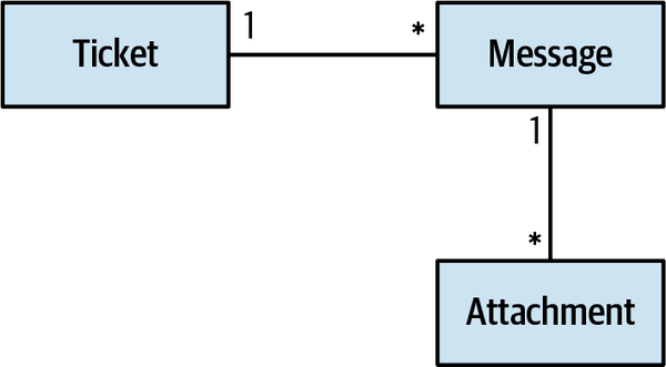
Figure 6-3. Aggregate as a hierarchy of entities
The hierarchy contains both entities and value objects,
The following code sample demonstrates a business rule that spans multiple entities belonging to the aggregate’s boundary—“If an agent didn’t open an escalated ticket within 50% of the response time limit, it is automatically reassigned to a different agent”:
01publicclassTicket02{03...04List<Message>_messages;05...0607publicvoidExecute(EvaluateAutomaticActionscmd)08{09if(this.IsEscalated&&this.RemainingTimePercentage<0.5&&10GetUnreadMessagesCount(for:AssignedAgent)>0)11{12_agent=AssignNewAgent();13}14}1516publicintGetUnreadMessagesCount(UserIdid)17{18return_messages.Where(x=>x.To==id&&!x.WasRead).Count();19}2021...22}
The method checks the ticket’s values to see whether it is escalated and whether the remaining processing time is less than the defined threshold of 50% (line 9). Furthermore, it checks for messages that were not yet read by the current agent (line 10). If all conditions are met, the ticket is requested to be reassigned to a different agent.
Referencing other aggregates
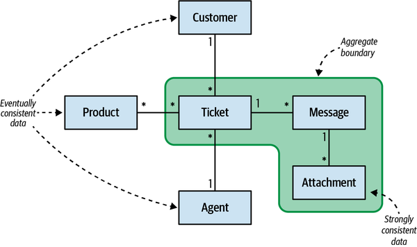
Figure 6-4. Aggregate as consistency boundary
The rule of thumb is to keep the aggregates as small as possible and include only objects that are required to be in a strongly consistent state by the aggregate’s business logic:
publicclassTicket{privateUserId_customer;privateList<ProductId>_products;privateUserId_assignedAgent;privateList<Message>_messages;...}
In the preceding example, the Ticket aggregate references a collection of messages, which belong to the aggregate’s boundary. On the other hand, the customer, the collection of products that are relevant to the ticket, and the assigned agent do not belong to the aggregate and therefore are referenced by its ID.
The reasoning behind referencing external aggregates by ID is to reify that these objects do not belong to the aggregate’s boundary, and to ensure that each aggregate has its own transactional boundary.
To decide whether an entity belongs to an aggregate or not, examine whether the aggregate contains business logic that can lead to an invalid system state if it will work on eventually consistent data. Let’s go back to the previous example of reassigning the ticket if the current agent didn’t read the new messages within 50% of the response time limit. What if the information about read/unread messages would be eventually consistent? In other words, it would be reasonable to receive reading acknowledgment after a certain delay. In that case, it’s safe to expect a considerable number of tickets to be unnecessarily reassigned. That, of course, would corrupt the system’s state. Therefore, the data in the messages belongs to the aggregate’s boundary.
The aggregate root
We saw earlier that an aggregate’s state can only be modified
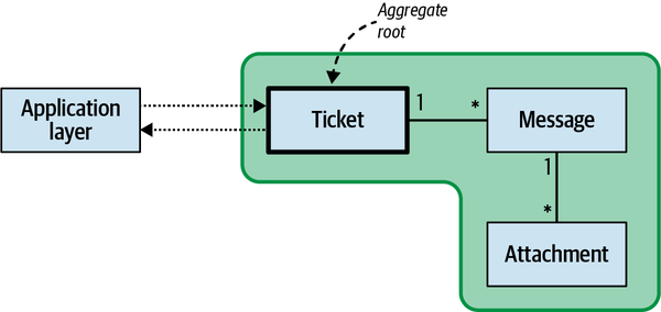
Figure 6-5. Aggregate root
Consider the following excerpt of the Ticket aggregate:
publicclassTicket{...List<Message>_messages;...publicvoidExecute(AcknowledgeMessagecmd){varmessage=_messages.Where(x=>x.Id==cmd.id).First();message.WasRead=true;}...}
In this example, the aggregate exposes a command that allows marking a specific message as read. Although the operation modifies an instance of the Message entity, it is accessible only through its aggregate root: Ticket.
In addition to the aggregate root’s public interface, there is another mechanism through which the outer world can communicate with aggregates: domain events.
Domain events
-
Ticket assigned
-
Ticket escalated
-
Message received
Since domain events describe something that has already happened, their names should be formulated in the past tense.
The goal of a domain event is to describe what has happened in the business domain and provide all the necessary data related to the event. For example, the following domain event communicates that the specific ticket was escalated, at what time, and for what reason:
{"ticket-id":"c9d286ff-3bca-4f57-94d4-4d4e490867d1","event-id":146,"event-type":"ticket-escalated","escalation-reason":"missed-sla","escalation-time":1628970815}
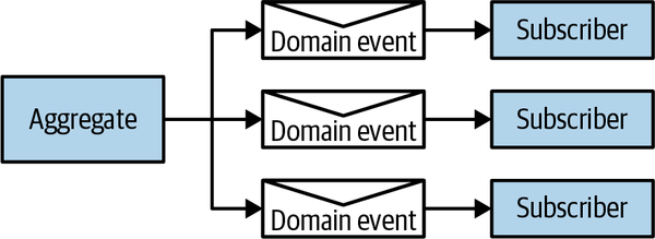
Figure 6-6. Domain events publishing flow
In the following excerpt from the Ticket aggregate, a new domain event is instantiated (line 12) and appended to the collection of the ticket’s domain events (line 13):
01publicclassTicket02{03...04privateList<DomainEvent>_domainEvents;05...0607publicvoidExecute(RequestEscalationcmd)08{09if(!this.IsEscalated&&this.RemainingTimePercentage<=0)10{11this.IsEscalated=true;12varescalatedEvent=newTicketEscalated(_id,cmd.Reason);13_domainEvents.Append(escalatedEvent);14}15}1617...18}
In Chapter 9, we will discuss how domain events can be reliably published to interested subscribers.
Ubiquitous language
Last but not least, aggregates should reflect the ubiquitous language.
Domain services
A domain service is a stateless object that implements the business logic. In the vast majority of cases, such logic orchestrates calls to various components of the system to perform some calculation or analysis.
Let’s go back to the example of the ticket aggregate. Recall that the assigned agent has a limited time frame in which to propose a solution to the customer. The time frame depends not only on the ticket’s data (its priority and escalation status), but also on the agent’s department policy regarding the SLAs for each priority and the agent’s work schedule (shifts)—we can’t expect the agent to respond during off-hours.
The response time frame calculation logic requires information from multiple sources: the ticket, the assigned agent’s department, and the work schedule. That makes it an ideal candidate to be implemented as a domain service:
publicclassResponseTimeFrameCalculationService{...publicResponseTimeframeCalculateAgentResponseDeadline(UserIdagentId,Prioritypriority,boolescalated,DateTimestartTime){varpolicy=_departmentRepository.GetDepartmentPolicy(agentId);varmaxProcTime=policy.GetMaxResponseTimeFor(priority);if(escalated){maxProcTime=maxProcTime*policy.EscalationFactor;}varshifts=_departmentRepository.GetUpcomingShifts(agentId,startTime,startTime.Add(policy.MaxAgentResponseTime));returnCalculateTargetTime(maxProcTime,shifts);}...}
It is also important to point out that domain services have nothing to do with microservices, service-oriented architecture, or almost any other use of the word service in software engineering. It is just a stateless object used to host business logic.
Managing Complexity
A system’s degrees of freedom are the data points needed to describe its state. Consider the following two classes:
publicclassClassA{publicintA{get;set;}publicintB{get;set;}publicintC{get;set;}publicintD{get;set;}publicintE{get;set;}}publicclassClassB{privateint_a,_d;publicintA{get=>_a;set{_a=value;B=value/2;C=value/3;}}publicintB{get;privateset;}publicintC{get;privateset;}publicintD{get=>_d;set{_d=value;E=value*2}}publicintE{get;privateset;}}
At first glance, it seems that ClassB is much more complex than ClassA. It has the same number of variables, but on top of that, it implements additional calculations. Is it more complex than ClassA?
Let’s analyze both classes from the degrees-of-freedom perspective. How many data elements do you need to describe the state of ClassA? The answer is five: its five variables. Hence, ClassA has five degrees of freedom.
How many data elements do you need to describe the state of ClassB? If you look at the assignment logic for properties A and D, you will notice that the values of B, C, and E are functions of the values of A and D. If you know what A and D are, then you can deduce the values of the rest of the variables. Therefore, ClassB has only two degrees of freedom. You need only two values to describe its state.
ClassA. The invariants introduced in ClassB reduce its complexity.All the business logic related to the state of a value object is located in its boundaries. The same is true for aggregates. An aggregate can only be modified by its own methods. Its business logic encapsulates and protects business invariants, thus reducing the degrees of freedom.
Since the domain model pattern is applied only for subdomains with complex business logic, it’s safe to assume that these are core subdomains—the heart of the software.
Conclusion
The domain model pattern is aimed at cases of complex business logic. It consists of three main building blocks:
- Value objects
-
Concepts of the business domain that can be identified exclusively by their values and thus do not require an explicit ID field. Since a change in one of the fields semantically creates a new value, value objects are immutable.
Value objects model not only data, but behavior as well: methods manipulating the values and thus initializing new value objects.
- Aggregates
-
A hierarchy of entities sharing a transactional boundary. All of the data included in an aggregate’s boundary has to be strongly consistent to implement its business logic.
The state of the aggregate, and its internal objects, can only be modified through its public interface, by executing the aggregate’s commands. The data fields are read-only for external components for the sake of ensuring that all the business logic related to the aggregate resides in its boundaries.
The aggregate acts as a transactional boundary. All of its data, including all of its internal objects, has to be committed to the database as one atomic transaction.
An aggregate can communicate with external entities by publishing domain events—messages describing important business events in the aggregate’s lifecycle. Other components can subscribe to the events and use them to trigger the execution of business logic.
- Domain services
- A stateless object that hosts business logic that naturally doesn’t belong to any of the domain model’s aggregates or value objects.
The domain model’s building blocks tackle the complexity of the business logic by encapsulating it in the boundaries of value objects and aggregates. The inability to modify the objects’ state externally ensures that all the relevant business logic is implemented in the boundaries of aggregates and value objects and won’t be duplicated in the application layer.
In the next chapter, you will learn the advanced way to implement the domain model pattern, this time making the dimension of time an inherent part of the model.
Exercises
-
Which of the following statements is true?
-
Value objects can only contain data.
-
Value objects can only contain behavior.
-
Value objects are immutable.
-
Value objects’ state can change.
-
-
What is the general guiding principle for designing the boundary of an aggregate?
-
An aggregate can contain only one entity as only one instance of an aggregate can be included in a single database transaction.
-
Aggregates should be designed to be as small as possible, as long as the business domain’s data consistency requirements are intact.
-
An aggregate represents a hierarchy of entities. Therefore, to maximize the consistency of the system’s data, aggregates should be designed to be as wide as possible.
-
It depends: for some business domains small aggregates are best, while in others it’s more efficient to work with aggregates that are as large as possible.
-
-
Why can only one instance of an aggregate be committed in one transaction?
-
To ensure that the model can perform under high load.
-
To ensure correct transactional boundaries.
-
There is no such requirement; it depends on the business domain.
-
To make it possible to work with databases that do not support multirecord transactions, such as key–value and document stores.
-
-
Which of the following statements best describes the relationships between the building blocks of a domain model?
-
Value objects describe entities’ properties.
-
Value objects can emit domain events.
-
An aggregate contains one or more entities.
-
A and C.
-
-
Which of the following statements is correct about differences between active records and aggregates?
-
Active records contain only data, whereas aggregates also contain behavior.
-
An aggregate encapsulates all of its business logic, but business logic manipulating an active record can be located outside of its boundary.
-
Aggregates contain only data, whereas active records contain both data and behavior.
-
An aggregate contains a set of active records.
-
2 All the code samples in this chapter will use an object-oriented programming language. However, the discussed concepts are not limited to OOP and are as relevant for the functional programming paradigm.
3 POCOs in .NET, POJOs in Java, POPOs in Python, etc.
4 “Primitive Obsession.” (n.d.) Retrieved June 13, 2021, from https://wiki.c2.com/?PrimitiveObsession.
5 In C# 9.0, the new type record implements value-based equality and thus doesn’t require overriding the equality operators.
6 Also
8 Recall that the application layer is a collection of transaction scripts, and as we discussed in Chapter 5, concurrency management is essential to prevent competing updates from corrupting the system’s data.
Chapter 7. Modeling the Dimension of Time
In the previous chapter, you learned about the domain model pattern: its building blocks,
This chapter starts by introducing the notion of event sourcing. Then it covers how event sourcing can be combined with the domain model pattern, making it an event-sourced domain model.
Event Sourcing
Show me your flowchart and conceal your tables,and I shall continue to be mystified. Show me your tables, and I won’t usually need your flowchart; it’ll be obvious.Fred Brooks1
Let’s use Fred Brooks’s reasoning to define the event sourcing pattern and understand how it differs from traditional modeling and persisting of data. Examine Table 7-1 and analyze what you can learn from this data about the system it belongs to.
| lead-id | first-name | last-name | status | phone-number | followup-on | created-on | updated-on |
|---|---|---|---|---|---|---|---|
| 1 | Sean | Callahan | CONVERTED | 555-1246 | 2019-01-31T10:02:40.32Z | 2019-01-31T10:02:40.32Z | |
| 2 | Sarah | Estrada | CLOSED | 555-4395 | 2019-03-29T22:01:41.44Z | 2019-03-29T22:01:41.44Z | |
| 3 | Stephanie | Brown | CLOSED | 555-1176 | 2019-04-15T23:08:45.59Z | 2019-04-15T23:08:45.59Z | |
| 4 | Sami | Calhoun | CLOSED | 555-1850 | 2019-04-25T05:42:17.07Z | 2019-04-25T05:42:17.07Z | |
| 5 | William | Smith | CONVERTED | 555-3013 | 2019-05-14T04:43:57.51Z | 2019-05-14T04:43:57.51Z | |
| 6 | Sabri | Chan | NEW_LEAD | 555-2900 | 2019-06-19T15:01:49.68Z | 2019-06-19T15:01:49.68Z | |
| 7 | Samantha | Espinosa | NEW_LEAD | 555-8861 | 2019-07-17T13:09:59.32Z | 2019-07-17T13:09:59.32Z | |
| 8 | Hani | Cronin | CLOSED | 555-3018 | 2019-10-09T11:40:17.13Z | 2019-10-09T11:40:17.13Z | |
| 9 | Sian | Espinoza | FOLLOWUP_SET | 555-6461 | 2019-12-04T01:49:08.05Z | 2019-12-04T01:49:08.05Z | 2019-12-04T01:49:08.05Z |
| 10 | Sophia | Escamilla | CLOSED | 555-4090 | 2019-12-06T09:12:32.56Z | 2019-12-06T09:12:32.56Z | |
| 11 | William | White | FOLLOWUP_SET | 555-1187 | 2020-01-23T00:33:13.88Z | 2020-01-23T00:33:13.88Z | 2020-01-23T00:33:13.88Z |
| 12 | Casey | Davis | CONVERTED | 555-8101 | 2020-05-20T09:52:55.95Z | 2020-05-27T12:38:44.12Z | |
| 13 | Walter | Connor | NEW_LEAD | 555-4753 | 2020-04-20T06:52:55.95Z | 2020-04-20T06:52:55.95Z | |
| 14 | Sophie | Garcia | CONVERTED | 555-1284 | 2020-05-06T18:47:04.70Z | 2020-05-06T18:47:04.70Z | |
| 15 | Sally | Evans | PAYMENT_FAILED | 555-3230 | 2020-06-04T14:51:06.15Z | 2020-06-04T14:51:06.15Z | |
| 16 | Scott | Chatman | NEW_LEAD | 555-6953 | 2020-06-09T09:07:05.23Z | 2020-06-09T09:07:05.23Z | |
| 17 | Stephen | Pinkman | CONVERTED | 555-2326 | 2020-07-20T00:56:59.94Z | 2020-07-20T00:56:59.94Z | |
| 18 | Sara | Elliott | PENDING_PAYMENT | 555-2620 | 2020-08-12T17:39:43.25Z | 2020-08-12T17:39:43.25Z | |
| 19 | Sadie | Edwards | FOLLOWUP_SET | 555-8163 | 2020-10-22T12:40:03.98Z | 2020-10-22T12:40:03.98Z | 2020-10-22T12:40:03.98Z |
| 20 | William | Smith | PENDING_PAYMENT | 555-9273 | 2020-11-13T08:14:07.17Z | 2020-11-13T08:14:07.17Z |
It’s evident that the table is used to manage potential customers, or leads, in a telemarketing system. For each lead, you can see their ID, their first and last names, when the record was created and updated, their phone number, and the lead’s current status.
By examining the various statuses, we can also assume the processing cycle each potential customer goes through:
-
The sales flow starts with the potential customer in the
NEW_LEADstatus. -
A sales call can end with the person not being interested in the offer (the lead is
CLOSED), scheduling a follow-up call (FOLLOWUP_SET), or accepting the offer (PENDING_PAYMENT). -
If the payment is successful, the lead is
CONVERTEDinto a customer. Conversely, the payment can fail—PAYMENT_FAILED.
That’s quite a lot of information that we can gather just by analyzing a table’s schema and the data stored in it. We can even assume what ubiquitous language was used when modeling the data. But what information is missing from that table?
The table’s data documents the leads’ current states, but it misses the story of how each lead got to their current state. We can’t analyze what was happening during the lifecycles of leads. We don’t know how many calls were made before a lead became CONVERTED. Was a purchase made right away, or was there a lengthy sales journey? Based on the historical data, is it worth trying to contact a person after multiple follow-ups, or is it more efficient to close the lead and move to a more promising prospect? None of that information is there. All we know are the leads’ current states.
These questions reflect business concerns essential for optimizing the sales process. From a business standpoint, it’s crucial to analyze the data and optimize the process based on the experience. One of the ways to fill in the missing information is to use event sourcing.
The event sourcing pattern introduces the dimension of time into the data model. Instead of the schema reflecting the aggregates’ current state, an event sourcing–based system persists events documenting every change in an aggregate’s lifecycle.
Consider the CONVERTED customer on line 12 in Table 7-1. The following listing demonstrates how the person’s data would be represented in an event-sourced system:
{"lead-id":12,"event-id":0,"event-type":"lead-initialized","first-name":"Casey","last-name":"David","phone-number":"555-2951","timestamp":"2020-05-20T09:52:55.95Z"},{"lead-id":12,"event-id":1,"event-type":"contacted","timestamp":"2020-05-20T12:32:08.24Z"},{"lead-id":12,"event-id":2,"event-type":"followup-set","followup-on":"2020-05-27T12:00:00.00Z","timestamp":"2020-05-20T12:32:08.24Z"},{"lead-id":12,"event-id":3,"event-type":"contact-details-updated","first-name":"Casey","last-name":"Davis","phone-number":"555-8101","timestamp":"2020-05-20T12:32:08.24Z"},{"lead-id":12,"event-id":4,"event-type":"contacted","timestamp":"2020-05-27T12:02:12.51Z"},{"lead-id":12,"event-id":5,"event-type":"order-submitted","payment-deadline":"2020-05-30T12:02:12.51Z","timestamp":"2020-05-27T12:02:12.51Z"},{"lead-id":12,"event-id":6,"event-type":"payment-confirmed","status":"converted","timestamp":"2020-05-27T12:38:44.12Z"}
The events in the listing tell the customer’s story. The lead was created in the system (event 0) and was contacted by a sales agent about two hours later (event 1). During the call, it was agreed that the sales agent would call back a week later (event 2), but to a different phone number (event 3). The sales agent also fixed a typo in the last name (event 3). The lead was contacted on the agreed date and time (event 4) and submitted an order (event 5). The order was to be paid in three days (event 5), but the payment was received about half an hour later (event 6), and the lead was converted into a new customer.
As we saw earlier, the customer’s state can easily be projected out from these domain events. All we have to do is apply simple transformation logic sequentially to each event:
publicclassLeadSearchModelProjection{publiclongLeadId{get;privateset;}publicHashSet<string>FirstNames{get;privateset;}publicHashSet<string>LastNames{get;privateset;}publicHashSet<PhoneNumber>PhoneNumbers{get;privateset;}publicintVersion{get;privateset;}publicvoidApply(LeadInitialized@event){LeadId=@event.LeadId;FirstNames=newHashSet<string>();LastNames=newHashSet<string>();PhoneNumbers=newHashSet<PhoneNumber>();FirstNames.Add(@event.FirstName);LastNames.Add(@event.LastName);PhoneNumbers.Add(@event.PhoneNumber);Version=0;}publicvoidApply(ContactDetailsChanged@event){FirstNames.Add(@event.FirstName);LastNames.Add(@event.LastName);PhoneNumbers.Add(@event.PhoneNumber);Version+=1;}publicvoidApply(Contacted@event){Version+=1;}publicvoidApply(FollowupSet@event){Version+=1;}publicvoidApply(OrderSubmitted@event){Version+=1;}publicvoidApply(PaymentConfirmed@event){Version+=1;}}
Iterating an aggregate’s events and feeding them sequentially into the appropriate overrides of the Apply method will produce precisely the state representation modeled in the table in Table 7-1.
Pay attention to the Version field
Finally, we are not limited to projecting only a single state representation of the events! Consider the following scenarios.
Search
publicclassLeadSearchModelProjection{publiclongLeadId{get;privateset;}publicHashSet<string>FirstNames{get;privateset;}publicHashSet<string>LastNames{get;privateset;}publicHashSet<PhoneNumber>PhoneNumbers{get;privateset;}publicintVersion{get;privateset;}publicvoidApply(LeadInitialized@event){LeadId=@event.LeadId;FirstNames=newHashSet<string>();LastNames=newHashSet<string>();PhoneNumbers=newHashSet<PhoneNumber>();FirstNames.Add(@event.FirstName);LastNames.Add(@event.LastName);PhoneNumbers.Add(@event.PhoneNumber);Version=0;}publicvoidApply(ContactDetailsChanged@event){FirstNames.Add(@event.FirstName);LastNames.Add(@event.LastName);PhoneNumbers.Add(@event.PhoneNumber);Version+=1;}publicvoidApply(Contacted@event){Version+=1;}publicvoidApply(FollowupSet@event){Version+=1;}publicvoidApply(OrderSubmitted@event){Version+=1;}publicvoidApply(PaymentConfirmed@event){Version+=1;}}
The projection logic uses the LeadInitialized and ContactDetailsChanged events to populate the respective sets of the lead’s personal details. Other events are ignored since they do not affect the specific model’s state.
Applying this projection logic to Casey Davis’s events from the earlier example will result in the following state:
LeadId: 12 FirstNames: ['Casey'] LastNames: ['David', 'Davis'] PhoneNumbers: ['555-2951', '555-8101'] Version: 6
Analysis
publicclassAnalysisModelProjection{publiclongLeadId{get;privateset;}publicintFollowups{get;privateset;}publicLeadStatusStatus{get;privateset;}publicintVersion{get;privateset;}publicvoidApply(LeadInitialized@event){LeadId=@event.LeadId;Followups=0;Status=LeadStatus.NEW_LEAD;Version=0;}publicvoidApply(Contacted@event){Version+=1;}publicvoidApply(FollowupSet@event){Status=LeadStatus.FOLLOWUP_SET;Followups+=1;Version+=1;}publicvoidApply(ContactDetailsChanged@event){Version+=1;}publicvoidApply(OrderSubmitted@event){Status=LeadStatus.PENDING_PAYMENT;Version+=1;}publicvoidApply(PaymentConfirmed@event){Status=LeadStatus.CONVERTED;Version+=1;}}
The preceding logic maintains a counter of the number of times follow-up events appeared in the lead’s events. If we were to apply this projection to the example of the aggregate’s events, it would generate the following state:
LeadId: 12 Followups: 1 Status: Converted Version: 6
Source of Truth
For the event sourcing pattern to work, all changes to an object’s state
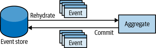
Figure 7-1. Event-sourced aggregate
The database that stores the system’s events is the only strongly consistent storage: the system’s source of truth. The accepted name for the database that is used for persisting events is event store.
Event Store
The event store should not allow modifying or deleting
interfaceIEventStore{IEnumerable<Event>Fetch(GuidinstanceId);voidAppend(GuidinstanceId,Event[]newEvents,intexpectedVersion);}
The expectedVersion argument in the Append method is needed to implement optimistic concurrency management: when you append new events, you also specify the version of the entity on which you are basing your decisions. If it’s stale, that is, new events were added after the expected version, the event store should raise a concurrency exception.
In most systems, additional endpoints are needed for implementing the CQRS pattern, as we will discuss in the next chapter.
Note
In essence, the event sourcing pattern is nothing new. The financial industry uses events to represent changes in a ledger. A ledger is an append-only log that documents transactions. A current state (e.g., account balance) can always be deduced by “projecting” the ledger’s records.
Event-Sourced Domain Model
Each operation on an event-sourced aggregate follows this script:
-
Load the aggregate’s domain events.
-
Reconstitute a state representation—project the events into a state representation that can be used to make business decisions.
-
Execute the aggregate’s command to execute the business logic, and consequently, produce new domain events.
-
Commit the new domain events to the event store.
Ticket aggregate The application service follows the script described earlier: it loads the relevant ticket’s events, rehydrates the aggregate instance, calls the relevant command, and persists changes back to the database:
01publicclassTicketAPI02{03privateITicketsRepository_ticketsRepository;04...0506publicvoidRequestEscalation(TicketIdid,EscalationReasonreason)07{08varevents=_ticketsRepository.LoadEvents(id);09varticket=newTicket(events);10varoriginalVersion=ticket.Version;11varcmd=newRequestEscalation(reason);12ticket.Execute(cmd);13_ticketsRepository.CommitChanges(ticket,originalVersion);14}1516...17}
The Ticket aggregate’s rehydration logic in the constructor (lines 27 through 31) instantiates an instance of the state projector class, TicketState, and sequentially calls its AppendEvent method for each of the ticket’s events:
18publicclassTicket19{20...21privateList<DomainEvent>_domainEvents=newList<DomainEvent>();22privateTicketState_state;23...2425publicTicket(IEnumerable<IDomainEvents>events)26{27_state=newTicketState();28foreach(vareinevents)29{30AppendEvent(e);31}32}
The AppendEvent passes the incoming events to the TicketState projection logic, thus generating the in-memory representation of the ticket’s current state:
33privatevoidAppendEvent(IDomainEvent@event)34{35_domainEvents.Append(@event);36// Dynamically call the correct overload of the "Apply" method.37((dynamic)state).Apply((dynamic)@event);38}
Contrary to the implementation we saw in the previous chapter, the event-sourced aggregate’s RequestEscalation method doesn’t explicitly set the IsEscalated flag to true. Instead, it instantiates the appropriate event and passes it to the AppendEvent method (lines 43 and 44):
39publicvoidExecute(RequestEscalationcmd)40{41if(!_state.IsEscalated&&_state.RemainingTimePercentage<=0)42{43varescalatedEvent=newTicketEscalated(_id,cmd.Reason);44AppendEvent(escalatedEvent);45}46}4748...49}
All events added to the aggregate’s events collection are passed to the state projection logic in the TicketState class, where the relevant fields’ values are mutated according to the events’ data:
50publicclassTicketState51{52publicTicketIdId{get;privateset;}53publicintVersion{get;privateset;}54publicboolIsEscalated{get;privateset;}55...56publicvoidApply(TicketInitialized@event)57{58Id=@event.Id;59Version=0;60IsEscalated=false;61....62}6364publicvoidApply(TicketEscalated@event)65{66IsEscalated=true;67Version+=1;68}6970...71}
Now let’s look at some of the advantages of leveraging event sourcing when implementing complex business logic.
Advantages
- Time traveling
- Just as the domain events can be used to reconstitute an aggregate’s current state,they can also be used to restore all past states of the aggregate. In other words, you can always reconstitute all the past states of an aggregate.
This is often done when analyzing the system’s behavior, inspecting the system’s decisions, and optimizing the business logic.
Another common use case for reconstituting past states isretroactive debugging: you can revert the aggregate to the exact state it was in when a bug was observed. - Deep insight
- InPart I of this book, we saw thatoptimizing core subdomains is strategically important for the business. Event sourcing provides deep insight into the system’s state and behavior. As you learned earlier in this chapter, event sourcing provides the flexible model that allows for transforming the events into different state representations—you can always add new projections that will leverage the existing events’ data to provide additional insights.
- Audit log
- The persisted domain events represent a strongly consistentaudit log of everything that has happened to the aggregates’ states. Laws oblige some business domains to implement such audit logs, and event sourcing provides this out of the box.
This model is especially convenient for systems managing money or monetary transactions. It allows us to easily trace the system’s decisions and the flow of funds between accounts.
- Advanced optimistic concurrency management
- The classic optimistic concurrency model raises an exceptionwhen the read data becomes stale—overwritten by another process—while it is being written.
When using event sourcing, we can gain deeper insight into exactly what has happened between reading the existing events and writing the new ones. You can query the exact events that were concurrently appended to the event store and make a business domain–driven decision as to whether the new events collide with the attempted operation or the additional events are irrelevant and it’s safe to proceed.
Disadvantages
- Learning curve
- The obvious disadvantage of the pattern is its sharp difference from the traditional techniques of managing data. Successful implementation of the pattern demands training of the team and time to get used to the new way of thinking. Unless the team already has experience implementing event-sourced systems, the learning curve has to be taken into account.
- Evolving the model
- Evolving an event-sourced model can be challenging. The strict definition of event sourcing says that events areimmutable. But what if you need to adjust the event’s schema? The process is not as simple as changing a table’s schema. In fact, a whole book was written on this subject alone:Versioning in an Event Sourced System by Greg Young.
- Architectural complexity
- Implementation of event sources introduces numerous architectural “moving parts,” making the overall design more complicated. This topic will be covered in more detail in the next chapter, when we discuss the CQRS architecture.
All of these challenges are even more acute if the task at hand doesn’t justify the use of the pattern and instead can be addressed by a simpler design. In Chapter 10, you will learn simple rules of thumb that can help you decide which business logic implementation pattern to use.
Frequently Asked Questions
When engineers are introduced to the event sourcing pattern, they often ask several common questions, so I find it obligatory to address them in this chapter.
Performance
- Reconstituting an aggregate’s state from events will negativelyaffect the system’s performance. It will degrade as events are added. How can this even work?
Projecting events into a state representation indeed requires compute power, and that need will grow as more events are added to an aggregate’s list.
It’s important to benchmark a projection’s impact on performance: the effect of working with hundreds or thousands of events. The results should be compared with the expected lifespan of an aggregate—the number of events expected to be recorded during an average lifespan.
In most systems, the performance hit will be noticeable only after 10,000+ events per aggregate. That said, in the vast majority of systems, an aggregate’s average lifespan won’t go over 100 events.
In the rare cases when projecting states does become a performance issue,another pattern can be implemented: snapshot. This pattern, shown inFigure 7-2, implements the following steps:-
A process continuously iterates new events in the event store, generates corresponding projections, and stores them in a cache.
-
An in-memory projection is needed to execute an action on the aggregate. In this case:
-
The process fetches the current state projection from the cache.
-
The process fetches the events that came after the snapshot version from the event store.
-
The additional events are applied in-memory to the snapshot.
-
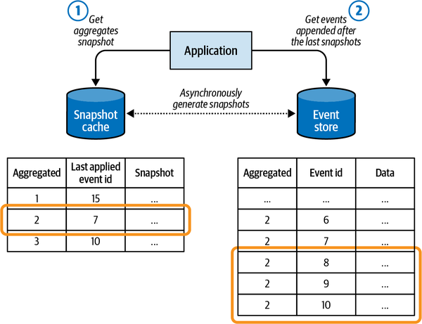
Figure 7-2. Snapshotting an aggregate’s events
It’s worth reiterating that the snapshot pattern is an optimization that has to be justified. If the aggregates in your system won’t persist 10,000+ events, implementing the snapshot pattern is just an accidental complexity. But before you go ahead and implement the snapshot pattern, I recommend that you take a step back and double-check the aggregate’s boundaries.
-
- This model generates enormous amounts of data. Can it scale?
The event-sourced model is easy to scale.
Since all aggregate-related operations are done in the context of a single aggregate, the event store can be sharded by aggregate IDs: all events belonging to an instance of an aggregate should reside in a single shard (seeFigure 7-3).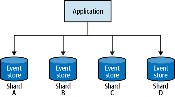
Figure 7-3. Sharding the event store
Deleting Data
- The event store is an append-only database,but what if I do need to delete data physically; for example, to comply with GDPR?3
This need can be addressed with the forgettable payload pattern:
all sensitive information is included in the events in encrypted form. The encryption key is stored in an external key–value store: the key storage, where the key is a specific aggregate’s ID and the value is the encryption key. When the sensitive data has to be deleted, the encryption key is deleted from the key storage. As a result, the sensitive information contained in the events is no longer accessible.
Why Can’t I Just…?
- Why can’t I just write logs to a text file and use it as an audit log?
- Writing data both to an operational database and to a logfile is an error-prone operation.In its essence, it’s a transaction against two storage mechanisms: the database and the file. If the first one fails, the second one has to be rolled back. For example, if a database transaction fails, no one cares to delete the prior log messages. Hence, such logs are not consistent, but rather, eventually inconsistent.
- Why can’t I keep working with a state-based model, but in the same database transaction, append logs to a logs table?
- From an infrastructural perspective, this approach does provideconsistent synchronization between the state and the log records. However, it is still error prone. What if the engineer who will be working on the codebase in the future forgets to append an appropriate log record?Furthermore, when the state-based representation is used as the source of truth,the additional log table’s schema usually degrades into chaos quickly. There is no way to enforce that all required information is written and that it is written in the correct format.
- Why can’t I just keep working with a state-based model but add a database trigger that will take a snapshot of the record and copy it into a dedicated “history” table?
This approach overcomes the previous one’s drawback: no explicit manual calls are needed to append records to the log table. That said, the resultant history only includes the dry facts: what fields were changed. It misses the business contexts: why the fields were changed. The lack of “why” drastically limits the ability to project additional models.
Conclusion
This chapter explained the event sourcing pattern and its application for modeling the dimension of time in the domain model’s aggregates.
In an event-sourced domain model, all changes to an aggregate’s state are expressed as a series of domain events. That’s in contrast to the more traditional approaches in which a state change just updates a record in the databases. The resultant domain events can be used to project the aggregate’s current state. Moreover, the event-based model gives us the flexibility to project the events into multiple representation models, each optimized for a specific task.
This pattern fits cases in which it’s crucial to have deep insight into the system’s data, whether for analysis and optimization or because an audit log is required by law.
This chapter completes our exploration of the different ways to model and implement business logic. In the next chapter, we will shift our attention to patterns belonging to a higher scope: architectural patterns.
Exercises
-
Which of the following statements is correct regarding the relationship between domain events and value objects?
-
Domain events use value objects to describe what has happened in the business domain.
-
When implementing an event-sourced domain model, value objects should be refactored into event-sourced aggregates.
-
Value objects are relevant for the domain model pattern, and are replaced by domain events in the event-sourced domain model.
-
All of the statements are incorrect.
-
-
Which of the following statements is correct regarding the options of projecting state from a series of events?
-
A single state representation can be projected from an aggregate’s events.
-
Multiple state representations can be projected, but the domain events have to be modeled in a way that supports multiple projections.
-
Multiple state representations can be projected and you can always add additional projections in the future.
-
All of the statements are incorrect.
-
-
Which of the following statements is correct regarding the difference between state-based and event-sourced aggregates?
-
An event-sourced aggregate can produce domain events, while a state-based aggregate cannot produce domain events.
-
Both variants of the aggregate pattern produce domain events, but only event-sourced aggregates use domain events as the source of truth.
-
Event-sourced aggregates ensure that domain events are generated for every state transition.
-
Both B and C are correct.
-
-
Going back to the WolfDesk company described in the book’s Preface, which functionality of the system lends itself to be implemented as an event-sourced domain model?
2 Except for exceptional cases, such as data migration.
3 General Data Protection Regulation. (n.d.) Retrieved June 14, 2021, from Wikipedia.
Chapter 8. Architectural Patterns
The tactical patterns discussed up to this point in the book defined the different ways to model and implement business logic. In this chapter, we will explore tactical design decisions in a broader context: the different ways to orchestrate the interactions and dependencies between a system’s components.
Business Logic Versus Architectural Patterns
Business logic is the most important part of software; however,
Architectural patterns introduce organizational principles for the different aspects of a codebase and present clear boundaries between them: how the business logic is wired to the system’s input, output, and other infrastructural components. This affects how these components interact with each other: what knowledge they share and how the components reference each other.
Choosing the appropriate way to organize the codebase, or the correct architectural pattern, is crucial to support implementation of the business logic in the short term and alleviate maintenance in the long term. Let’s explore three predominant application architecture patterns and their use cases: layered architecture, ports & adapters, and CQRS.
Layered Architecture
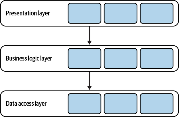
Figure 8-1. Layered architecture
In its classic form, the layered architecture consists of three layers: the presentation layer (PL), the business logic layer (BLL), and the data access layer (DAL).
Presentation Layer
The presentation layer, shown in Figure 8-2, implements
In modern systems, however, the presentation layer has a broader scope: that is, all means for triggering the program’s behavior, both synchronous and asynchronous. For example:
-
Graphical user interface (GUI)
-
Command-line interface (CLI)
-
API for programmatic integration with other systems
-
Subscription to events in a message broker
-
Message topics for publishing outgoing events
All of these are the means for the system to receive requests from the external environment and communicate the output. Strictly speaking, the presentation layer is the program’s public interface.
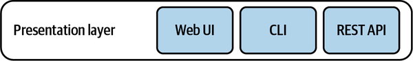
Figure 8-2. Presentation layer
Business Logic Layer
This layer is where the business logic patterns described in Chapters 5–7 are implemented—for example, active records or a domain model (see Figure 8-3).
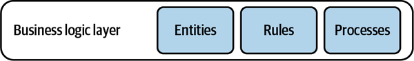
Figure 8-3. Business logic layer
Data Access Layer
The data access layer provides access to persistence mechanisms.
First, ever since the NoSQL revolution broke out, it is common for a system to work with multiple databases. For example, a document store can act as the operational database, a search index for dynamic queries, and an in-memory database for performance-optimized operations.
Finally, this layer also includes integration with the various external information providers needed to implement the program’s functionality: APIs provided by external systems, or cloud vendors’ managed services, such as language translation, stock market data, and audio transcription (see Figure 8-4).
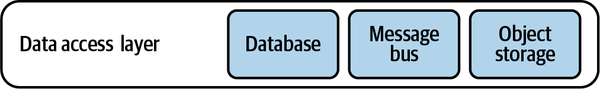
Figure 8-4. Data access layer
Communication Between Layers
The layers are integrated in a top-down communication model:
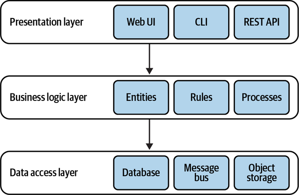
Figure 8-5. Layered architecture
Variation
It’s common to see the layered architecture pattern extended with an additional layer: the service layer.
Service layer
Defines an application’s boundary with a layer of services that
establishes a set of available operations and coordinates the application’s response in each operation.—Patterns of Enterprise Application Architecture4
The service layer acts as an intermediary between the
namespaceMvcApplication.Controllers{publicclassUserController:Controller{...[AcceptVerbs(HttpVerbs.Post)]publicActionResultCreate(ContactDetailscontactDetails){OperationResultresult=null;try{_db.StartTransaction();varuser=newUser();user.SetContactDetails(contactDetails)user.Save();_db.Commit();result=OperationResult.Success;}catch(Exceptionex){_db.Rollback();result=OperationResult.Exception(ex);}returnView(result);}}}
The MVC controller in this example belongs to the presentation layer. It exposes an endpoint that creates a new user. The endpoint uses the User active record object to create a new instance and save it. Moreover, it orchestrates a database transaction to ensure that a proper response is generated in case of an error.
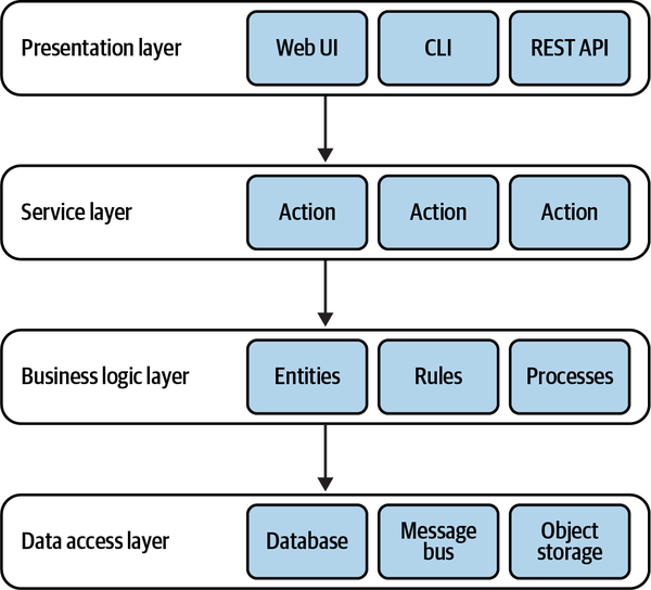
Figure 8-6. Service layer
It’s important to note that in the context of the architectural pattern,
interfaceCampaignManagementService{OperationResultCreateCampaign(CampaignDetailsdetails);OperationResultPublish(CampaignIdid,PublishingScheduleschedule);OperationResultDeactivate(CampaignIdid);OperationResultAddDisplayLocation(CampaignIdid,DisplayLocationnewLocation);...}
Let’s refactor the preceding example and extract the orchestration logic into a service layer:
namespaceServiceLayer{publicclassUserService{...publicOperationResultCreate(ContactDetailscontactDetails){OperationResultresult=null;try{_db.StartTransaction();varuser=newUser();user.SetContactDetails(contactDetails)user.Save();_db.Commit();result=OperationResult.Success;}catch(Exceptionex){_db.Rollback();result=OperationResult.Exception(ex);}returnresult;}...}}namespaceMvcApplication.Controllers{publicclassUserController:Controller{...[AcceptVerbs(HttpVerbs.Post)]publicActionResultCreate(ContactDetailscontactDetails){varresult=_userService.Create(contactDetails);returnView(result);}}}
Having an explicit service level has a number of advantages:
-
We can reuse the same service layer to serve multiple public interfaces; for example, a graphical user interface and an API. No duplication of the orchestration logic is required.
-
It improves modularity by gathering all related methods in one place.
-
It further decouples the presentation and business logic layers.
-
It makes it easier to test the business functionality.
That said, a service layer is not always necessary. For example, when the business logic is implemented as a transaction script, it essentially is a service layer, as it already exposes a set of methods that form the system’s public interface. In such a case, the service layer’s API would just repeat the transaction scripts’ public interfaces, without abstracting or encapsulating any complexity. Hence, either a service layer or a business logic layer will suffice.
Terminology
-
Presentation layer = user interface layer
-
Service layer = application layer
-
Business logic layer = domain layer = model layer
-
Data access layer = infrastructure layer
To eliminate confusion, I present the pattern using the original terminology. That said, I prefer “user interface layer” and “infrastructure layer” as these terms better reflect the responsibilities of modern systems and an application layer to avoid confusion with the physical boundaries of services.
When to Use Layered Architecture
Ports & Adapters
The ports & adapters architecture addresses the
Terminology
Figure 8-8. Presentation and data access layers combined into an infrastructure layer
Dependency Inversion Principle
The dependency inversion principle (DIP) states that
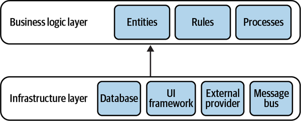
Figure 8-9. Reversed dependencies
Instead of being sandwiched between the technological concerns, now the business logic layer takes the central role. It doesn’t depend on any of the system’s infrastructural components.
Finally, let’s add an application5 layer as a façade for the
Figure 8-10. Traditional layers of the ports & adapters architecture
The architecture depicted in Figure 8-10 is the ports & adapters architectural pattern. The business logic doesn’t depend on any of the underlying layers, as required for implementing the domain model and event-sourced domain model patterns.
Why is this pattern called ports & adapters? To answer this question, let’s see how the infrastructural components are integrated with the business logic.
Integration of Infrastructural Components
The core goal of the ports & adapters architecture is to decouple
Figure 8-11. Ports & adapters architecture
The abstract ports are resolved into concrete adapters in the infrastructure layer, either through dependency injection or by bootstrapping.
For example, here is a possible port definition and a concrete adapter for a message bus:
namespaceApp.BusinessLogicLayer{publicinterfaceIMessaging{voidPublish(Messagepayload);voidSubscribe(Messagetype,Actioncallback);}}namespaceApp.Infrastructure.Adapters{publicclassSQSBus:IMessaging{...}}
Variants
The ports & adapters architecture is also known as hexagonal architecture,
-
Application layer = service layer = use case layer
-
Business logic layer = domain layer = core layer
Despite that, these patterns can be mistakenly treated as conceptually different. That’s just another example of the importance of a ubiquitous language.
When to Use Ports & Adapters
Command-Query Responsibility Segregation
Let’s see why we might need such a solution and how to implement it.
Polyglot Modeling
Another reason for working with multiple models may have to do with the notion of polyglot persistence. There is no perfect database.
That said, this chapter “decouples” CQRS from event sourcing. I intend to show that CQRS is useful even if the business logic is implemented using any of the other business logic implementation patterns.
Let’s see how CQRS allows the use of multiple storage mechanisms for representing different models of the system’s data.
Implementation
Command execution model
The command execution model is also the only model representing strongly consistent data—the system’s source of truth. It should be possible to read the strongly consistent state of a business entity and have optimistic concurrency support when updating it.
Read models (projections)
A read model is a precached projection. It can reside in a durable database, flat file, or in-memory cache. Proper implementation of CQRS allows for wiping out all data of a projection and regenerating it from scratch. This also enables extending the system with additional projections in the future—models that couldn’t have been foreseen originally.
Finally, read models are read-only. None of the system’s operations can directly modify the read models’ data.
Projecting Read Models
Figure 8-12. CQRS architecture
The projection of read models is similar to the notion of a materialized view in relational databases: whenever source tables are updated, the changes have to be reflected in the precached views.
Next, let’s see two ways to generate projections: synchronously and asynchronously.
Synchronous projections
Synchronous projections fetch changes to the OLTP data through the catch-up subscription model:
-
The projection engine queries the OLTP database for added or updated records after the last processed checkpoint.
-
The projection engine uses the updated data to regenerate/update the system’s read models.
-
The projection engine stores the checkpoint of the last processed record. This value will be used during the next iteration for getting records added or modified after the last processed record.
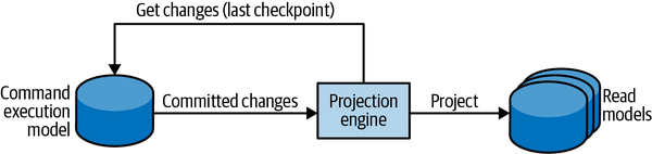
Figure 8-13. Synchronous projection model
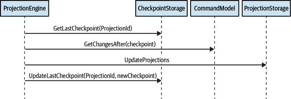
Figure 8-14. Synchronous projection of read models through catch-up subscription
For the catch-up subscription to work, the command execution model has to checkpoint all the appended or updated database records. The storage mechanism should also support the querying of records based on the checkpoint.
The checkpoint can be implemented using the databases’ features. For example, SQL Server’s “rowversion” column can be used to generate unique, incrementing numbers upon inserting or updating a row, as illustrated in Figure 8-15. In databases that lack such functionality, a custom solution can be implemented that increments a running counter and appends it to each modified record. It’s important to ensure that the checkpoint-based query returns consistent results. If the last returned record has a checkpoint value of 10, on the next execution no new requests should have values lower than 10. Otherwise, these records will be skipped by the projection engine, which will result in inconsistent models.
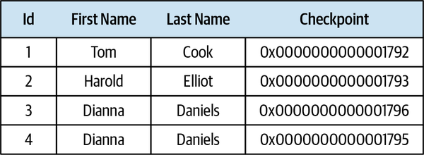
Figure 8-15. Auto-generated checkpoint column in a relational database
The synchronous projection method makes it trivial to add new projections and regenerate existing ones from scratch. In the latter case, all you have to do is reset the checkpoint to 0; the projection engine will scan the records and rebuild the projections from the ground up.
Asynchronous projections
In the asynchronous projection scenario, the command execution
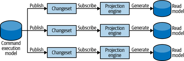
Figure 8-16. Asynchronous projection of read models
Challenges
Despite the apparent scaling and performance advantages of the
This method also makes it more challenging to add new projections or regenerate existing ones.
Model Segregation
A common misconception about CQRS-based systems is that a command can only modify data, and data can be fetched for display only through a read model. In other words, the command executing the methods should never return any data. This is wrong. This approach produces accidental complexities and leads to a bad user experience.
A command should always let the caller know whether it has succeeded or failed. If it has failed, why did it fail? Was there a validation or technical issue? The caller has to know how to fix the command. Therefore, a command can—and in many cases should—return data; for example, if the system’s user interface has to reflect the modifications resulting from the command. Not only does this make it easier for consumers to work with the system since they immediately receive feedback for their actions, but the returned values can be used further in the consumers’ workflows, eliminating the need for unnecessary data round trips.
The only limitation here is that the returned data should originate from the strongly consistent model—the command execution model—as we cannot expect the projections, which will eventually be consistent, to be refreshed immediately.
When to Use CQRS
Scope
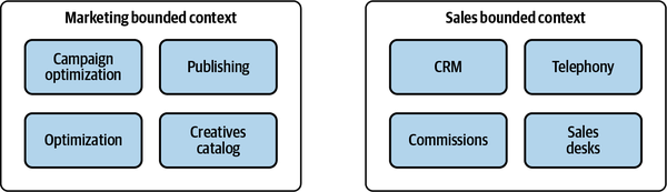
Figure 8-17. Bounded contexts spanning multiple subdomains
Our goal is to drive design decisions according to the actual needs and business strategy. In addition to the layers that partition the system horizontally, we can introduce additional vertical partitioning. It’s crucial to define logical boundaries for modules encapsulating distinct business subdomains and use the appropriate tools for each, as demonstrated in Figure 8-18.
Appropriate vertical boundaries make a monolithic bounded context a modular one and help to prevent it from becoming a big ball of mud. As we will discuss in Chapter 11, these logical boundaries can be refactored later into physical boundaries of finer-grained bounded contexts.
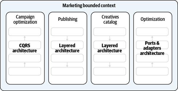
Figure 8-18. Architectural slices
Conclusion
The layered architecture decomposes the codebase based on its technological concerns. Since this pattern couples business logic with data access implementation, it’s a good fit for active record–based systems.
The ports & adapters architecture inverts the relationships: it puts the business logic at the center and decouples it from all infrastructural dependencies. This pattern is a good fit for business logic implemented with the domain model pattern.
The CQRS pattern represents the same data in multiple models. Although this pattern is obligatory for systems based on the event-sourced domain model, it can also be used in any systems that need a way of working with multiple persistent models.
The patterns we will discuss in the next chapter address architectural concerns from a different perspective: how to implement reliable interaction between different components of a system.
Exercises
-
Which of the discussed architectural patterns can be used with business logic implemented as the active record pattern?
-
Layered architecture
-
Ports & adapters
-
CQRS
-
A and C
-
-
Which of the discussed architectural patterns decouples the business logic from infrastructural concerns?
-
Layered architecture
-
Ports & adapters
-
CQRS
-
B and C
-
-
Assume you are implementing the ports & adapters pattern and need to integrate a cloud provider’s managed message bus. In which layer should the integration be implemented?
-
Business logic layer
-
Application layer
-
Infrastructure layer
-
Any layer
-
-
Which of the following statements is true regarding the CQRS pattern?
-
Asynchronous projections are easier to scale.
-
Either synchronous or asynchronous projection can be used, but not both at the same time.
-
A command cannot return any information to the caller. The caller should always use the read models to get the results of the executed actions.
-
A command can return information as long as it originates from a strongly consistent model.
-
A and D.
-
-
The CQRS pattern allows for representing the same business objects in multiple persistent models, and thus allows working with multiple models in the same bounded context. Does it contradict the bounded context’s notion of being a model boundary?
1 Evans, E. (2003). Domain-Driven Design: Tackling Complexity in the Heart of Software. Boston: Addison-Wesley.
2 Such as AWS S3 or Google Cloud Storage.
3 In this context, the message bus is used for the system’s internal needs. If it were exposed publicly, it would belong to the presentation layer.
4 Fowler, M. (2002). Patterns of Enterprise Application Architecture. Boston: Addison-Wesley.
5 Since we are not in the context of the layered architecture, I will take the freedom to use the term application layer instead of service layer, as it better reflects the purpose.
6 Polyglot data by Greg Young. (n.d.). Retrieved June 14, 2021, from YouTube.
Chapter 9. Communication Patterns
Chapters 5–8 presented tactical design patterns that define the different ways to implement a system’s components: how to model the business logic and how to organize the internals of a bounded context architecturally. In this chapter, we will step beyond the boundaries of a single component and discuss the patterns for organizing the flow of communication across a system’s elements.
The patterns you will learn about in this chapter facilitate cross-bounded context communication, address the limitations imposed by aggregate design principles, and orchestrate business processes spanning multiple system components.
Model Translation
A bounded context is the boundary of a model—a ubiquitous language.
In a customer–supplier relationship, the balance of power tips toward either the upstream (supplier) or the downstream (consumer) bounded context. Suppose the downstream bounded context cannot conform to the upstream bounded context’s model. In this case, a more elaborate technical solution is required that can facilitate communication by translating the bounded contexts’ models.
This translation can be handled by one, or sometimes both, sides: the downstream bounded context can adapt the upstream bounded context’s model to its needs using an anticorruption layer (ACL), while the upstream bounded context can act as an open-host service (OHS) and protect its consumers from changes to its implementation model by using an integration-specific published language. Since the translation logic is similar for both the anticorruption layer and the open-host service, this chapter covers the implementation options without differentiating between the patterns and mentions the differences only in exceptional cases.
Stateless Model Translation
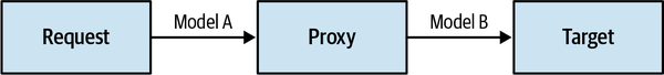
Figure 9-1. Model translation by a proxy
Implementation of the proxy depends on whether the bounded contexts are communicating synchronously or asynchronously.
Synchronous
The typical way to translate models used in synchronous communication
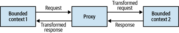
Figure 9-2. Synchronous communication
In some cases, it can be more cost-effective and convenient to offload the translation logic to an external component such as an API gateway pattern. The API gateway component can be an open source software-based solution such as Kong or KrakenD, or it can be a cloud vendor’s managed service such as AWS API Gateway, Google Apigee, or Azure API Management.
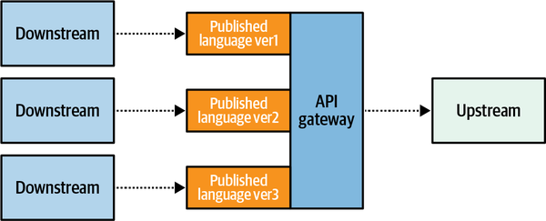
Figure 9-3. Exposing different versions of the published language
Anticorruption layers implemented using an API gateway can be consumed by multiple downstream bounded contexts. In such cases, the anticorruption layer acts as an integration-specific bounded context, as shown in Figure 9-4.
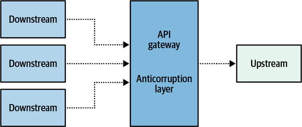
Figure 9-4. Shared anticorruption layer
Such bounded contexts, which are mainly in charge of transforming models for more convenient consumption by other components, are often referred to as interchange contexts.
Asynchronous
To translate models used in asynchronous communication
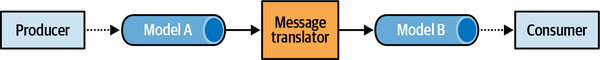
Figure 9-5. Translating models in asynchronous communication
In addition to translating the messages’ model, the intercepting component can also reduce the noise on the target bounded context by filtering out irrelevant messages.
Asynchronous model translation is essential when implementing an open host service. It’s a common mistake to design and expose a published language for the model’s objects and allow domain events to be published as they are, thereby exposing the bounded context’s implementation model. Asynchronous translation can be used to intercept the domain events and convert them into a published language, thus providing better encapsulation of the bounded context’s implementation details (see Figure 9-6).
Moreover, translating messages to the published language enables
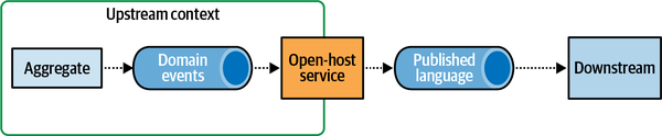
Figure 9-6. Domain events in a published language
Stateful Model Translation
Aggregating incoming data
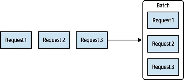
Figure 9-7. Batching requests
Another common use case for aggregation of source data is combining multiple fine-grained messages into a single message containing the unified data, as depicted in Figure 9-8.
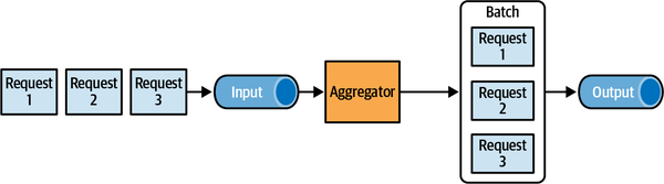
Figure 9-8. Unifying incoming events
Model transformation that aggregates incoming data cannot be implemented using an API gateway, and thus requires more elaborate, stateful processing. To track the incoming data and process it accordingly, the translation logic requires its own persistent storage (see Figure 9-9).
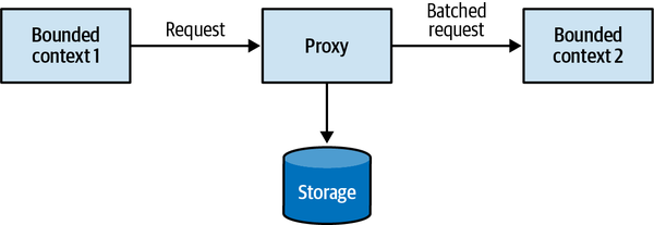
Figure 9-9. Stateful model transformation
In some use cases, you can avoid implementing a custom solution for a stateful translation by using off-the-shelf products; for example, a stream-process platform (Kafka, AWS Kinesis, etc.), or a batching solution (Apache NiFi, AWS Glue, Spark, etc.).
Unifying multiple sources
A bounded context may need to process data aggregates from multiple sources,
Another example is a bounded context that must process data from multiple other contexts and implement complex business logic to process all the data. In this case, it can be beneficial to decouple the integration and business logic complexities by fronting the bounded context with an anticorruption layer that aggregates data from all other bounded contexts, as shown in Figure 9-10.
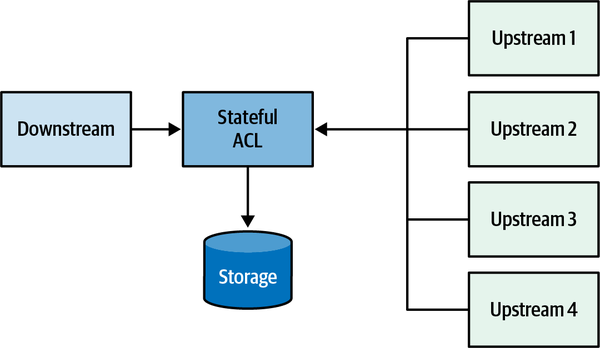
Figure 9-10. Simplifying the integration model using the anticorruption layer pattern
Integrating Aggregates
Before we get to the solution, let’s examine a few common mistakes in the event publishing process and the consequences of each approach. Consider the following code:
01publicclassCampaign02{03...04List<DomainEvent>_events;05IMessageBus_messageBus;06...0708publicvoidDeactivate(stringreason)09{10for(lin_locations.Values())11{12l.Deactivate();13}1415IsActive=false;1617varnewEvent=newCampaignDeactivated(_id,reason);18_events.Append(newEvent);19_messageBus.Publish(newEvent);20}21}
On line 17, a new event is instantiated. On the following two lines, it is appended to the aggregate’s internal list of domain events (line 18), and the event is published to the message bus (line 19). This implementation of publishing domain events is simple but wrong. Publishing the domain event right from the aggregate is bad for two reasons. First, the event will be dispatched before the aggregate’s new state is committed to the database. A subscriber may receive the notification that the campaign was deactivated, but it would contradict the campaign’s state. Second, what if the database transaction fails to commit because of a race condition, subsequent aggregate logic rendering the operation invalid, or simply a technical issue in the database? Even though the database transaction is rolled back, the event is already published and pushed to subscribers, and there is no way to retract it.
Let’s try something else:
01publicclassManagementAPI02{03...04privatereadonlyIMessageBus_messageBus;05privatereadonlyICampaignRepository_repository;06...07publicExecutionResultDeactivateCampaign(CampaignIdid,stringreason)08{09try10{11varcampaign=repository.Load(id);12campaign.Deactivate(reason);13_repository.CommitChanges(campaign);1415varevents=campaign.GetUnpublishedEvents();16for(IDomainEventeinevents)17{18_messageBus.publish(e);19}20campaign.ClearUnpublishedEvents();21}22catch(Exceptionex)23{24...25}26}27}
In the preceding listing, the responsibility of publishing new domain events is shifted to the application layer. On lines 11 through 13, the relevant instance of the Campaign aggregate is loaded, its Deactivate command is executed, and only after the updated state is successfully committed to the database, on lines 15 through 20, are the new domain events published to the message bus. Can we trust this code? No.
In this case, the process running the logic for some reason fails to publish the domain events. Perhaps the message bus is down. Or the server running the code fails right after committing the database transaction, but before publishing the events the system will still end in an inconsistent state, which means that the database transaction is committed, but the domain events will never be published.
These edge cases can be addressed using the outbox pattern.
Outbox
-
Both the updated aggregate’s state and the new domain events are committed in the same atomic transaction.
-
A message relay fetches newly committed domain events from the database.
-
The relay publishes the domain events to the message bus.
-
Upon successful publishing, the relay either marks the events as
publishedin the database or deletes them completely.
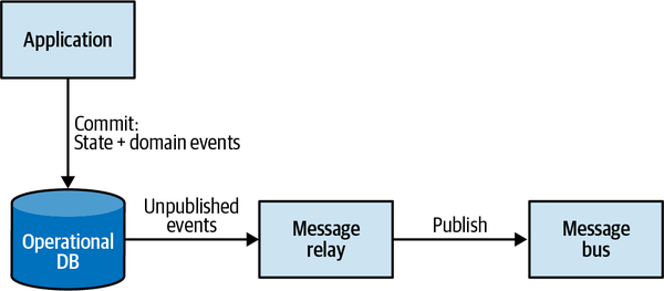
Figure 9-11. Outbox pattern
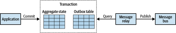
Figure 9-12. Outbox table
When using a NoSQL database that doesn’t support multidocument transactions, the outgoing domain events have to be embedded in the aggregate’s record. For example:
{"campaign-id":"364b33c3-2171-446d-b652-8e5a7b2be1af","state":{"name":"Autumn 2017","publishing-state":"DEACTIVATED","ad-locations":[...]...},"outbox":[{"campaign-id":"364b33c3-2171-446d-b652-8e5a7b2be1af","type":"campaign-deactivated","reason":"Goals met","published":false}]}
In this sample, you can see the JSON document’s additional property, outbox, containing a list of domain events that have to be published.
Fetching unpublished events
The publishing relay can fetch the new domain events in either a pull-based or push-based manner:
- Pull: polling publisher
- The relay can continuously query the database for unpublished events. Proper indexes have to be in place to minimize the load on the database induced by the constant polling.
- Push: transaction log tailing
- Here we can leverage the database’s feature set to proactively call the publishing relay when new events are appended. For example, some relational databases enable getting notifications about updated/inserted records by tailing the database’s transaction log. Some NoSQL databases expose committed changes as streams of events (e.g., AWS DynamoDB Streams).
It’s important to note that the outbox pattern guarantees delivery of the messages at least once: if the relay fails right after publishing a message but before marking it as published in the database, the same message will be published again in the next iteration.
Next, we’ll take a look at how we can leverage the reliable publishing of domain events to overcome some of the limitations imposed by aggregate design principles.
Saga
One of the core aggregate design principles is to limit each transaction
Published. In the case of rejection by the publisher, the campaign should be marked as Rejected.This flow spans two business entities: advertising campaign and publisher. Co-locating the entities in the same aggregate boundary would definitely be overkill, as these are clearly different business entities that have different responsibilities and may belong to different bounded contexts. Instead, this flow can be implemented as a saga.
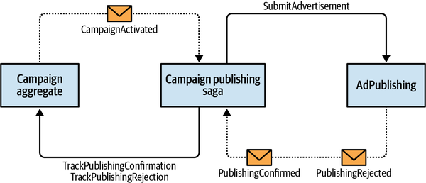
Figure 9-13. Saga
To implement the publishing process, the saga has to listen to the CampaignActivated event from the Campaign aggregate and the PublishingConfirmed and PublishingRejected events from the AdPublishing bounded context. The saga has to execute the SubmitAdvertisement command on AdPublishing, and the TrackPublishingConfirmation and TrackPublishingRejection commands on the Campaign aggregate. In this example, the TrackPublishingRejection command acts as a compensation action that will ensure that the advertising campaign is not listed as active. Here is the code:
publicclassCampaignPublishingSaga{privatereadonlyICampaignRepository_repository;privatereadonlyIPublishingServiceClient_publishingService;...publicvoidProcess(CampaignActivated@event){varcampaign=_repository.Load(@event.CampaignId);varadvertisingMaterials=campaign.GenerateAdvertisingMaterials();_publishingService.SubmitAdvertisement(@event.CampaignId,advertisingMaterials);}publicvoidProcess(PublishingConfirmed@event){varcampaign=_repository.Load(@event.CampaignId);campaign.TrackPublishingConfirmation(@event.ConfirmationId);_repository.CommitChanges(campaign);}publicvoidProcess(PublishingRejected@event){varcampaign=_repository.Load(@event.CampaignId);campaign.TrackPublishingRejection(@event.RejectionReason);_repository.CommitChanges(campaign);}}
The preceding example relies on the messaging infrastructure to deliver the relevant events, and it reacts to the events by executing the relevant commands. This is an example of a relatively simple saga: it has no state. You will encounter sagas that do require state management; for example, to track the executed operations so that relevant compensating actions can be issued in case of a failure. In such a situation, the saga can be implemented as an event-sourced aggregate, persisting the complete history of received events and issued commands. However, the command execution logic should be moved out of the saga itself and executed asynchronously, similar to the way domain events are dispatched in the outbox pattern:
publicclassCampaignPublishingSaga{privatereadonlyICampaignRepository_repository;privatereadonlyIList<IDomainEvent>_events;...publicvoidProcess(CampaignActivatedactivated){varcampaign=_repository.Load(activated.CampaignId);varadvertisingMaterials=campaign.GenerateAdvertisingMaterials();varcommandIssuedEvent=newCommandIssuedEvent(target:Target.PublishingService,command:newSubmitAdvertisementCommand(activated.CampaignId,advertisingMaterials));_events.Append(activated);_events.Append(commandIssuedEvent);}publicvoidProcess(PublishingConfirmedconfirmed){varcommandIssuedEvent=newCommandIssuedEvent(target:Target.CampaignAggregate,command:newTrackConfirmation(confirmed.CampaignId,confirmed.ConfirmationId));_events.Append(confirmed);_events.Append(commandIssuedEvent);}publicvoidProcess(PublishingRejectedrejected){varcommandIssuedEvent=newCommandIssuedEvent(target:Target.CampaignAggregate,command:newTrackRejection(rejected.CampaignId,rejected.RejectionReason));_events.Append(rejected);_events.Append(commandIssuedEvent);}}
In this example, the outbox relay will have to execute the commands on relevant endpoints for each instance of CommandIssuedEvent. As in the case of publishing domain events, separating the transition of the saga’s state from the execution of commands ensures that the commands will be executed reliably, even if the process fails at any stage.
Consistency
Although the saga pattern orchestrates a multicomponent transaction,
Only the data within an aggregate’s boundaries can be considered strongly consistent. Everything outside is eventually consistent.
Use this as a guiding principle to make sure you are not abusing sagas to compensate for improper aggregate boundaries. Business operations that have to belong to the same aggregate require strongly consistent data.
Process Manager
-
CampaignActivatedevent toPublishingService.SubmitAdvertisementcommand -
PublishingConfirmedevent toCampaign.TrackConfirmationcommand -
PublishingRejectedevent toCampaign.TrackRejectioncommand
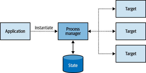
Figure 9-14. Process manager
As a simple rule of thumb, if a saga contains if-else statements to choose the correct course of action, it is probably a process manager.
Another difference between a process manager and a saga is that a saga is instantiated implicitly when a particular event is observed, as in CampaignActivated in the preceding examples. A process manager, on the other hand, cannot be bound to a single source event. Instead, it’s a coherent business process consisting of multiple steps. Hence, a process manager has to be instantiated explicitly. Consider the following example:
Booking a business trip starts with the routing algorithm choosing the most cost-effective flight route and asking the employee to approve it. In case the employee prefers a different route, their direct manager needs to approve it. After the flight is booked, one of the preapproved hotels has to be booked for the appropriate dates. If no hotels are available, the flight tickets have to be canceled.
In this example, there is no central entity to trigger the trip booking process. The trip booking is the process and it has to be implemented as a process manager (see Figure 9-15).
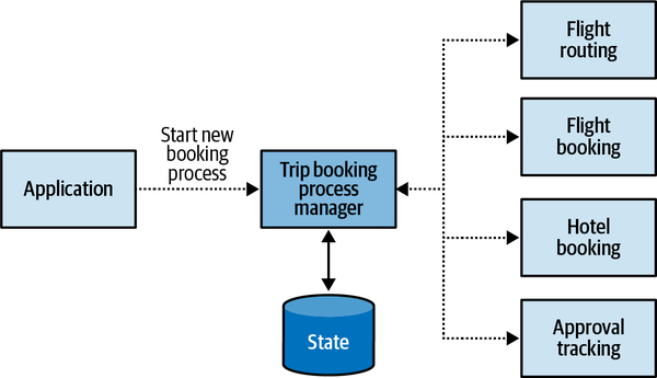
Figure 9-15. Trip booking process manager
From an implementation perspective, process managers are often implemented as aggregates, either state based or event sourced. For example:
publicclassBookingProcessManager{privatereadonlyIList<IDomainEvent>_events;privateBookingId_id;privateDestination_destination;privateTripDefinition_parameters;privateEmployeeId_traveler;privateRoute_route;privateIList<Route>_rejectedRoutes;privateIRoutingService_routing;...publicvoidInitialize(Destinationdestination,TripDefinitionparameters,EmployeeIdtraveler){_destination=destination;_parameters=parameters;_traveler=traveler;_route=_routing.Calculate(destination,parameters);varrouteGenerated=newRouteGeneratedEvent(BookingId:_id,Route:_route);varcommandIssuedEvent=newCommandIssuedEvent(command:newRequestEmployeeApproval(_traveler,_route));_events.Append(routeGenerated);_events.Append(commandIssuedEvent);}publicvoidProcess(RouteConfirmedconfirmed){varcommandIssuedEvent=newCommandIssuedEvent(command:newBookFlights(_route,_parameters));_events.Append(confirmed);_events.Append(commandIssuedEvent);}publicvoidProcess(RouteRejectedrejected){varcommandIssuedEvent=newCommandIssuedEvent(command:newRequestRerouting(_traveler,_route));_events.Append(rejected);_events.Append(commandIssuedEvent);}publicvoidProcess(ReroutingConfirmedconfirmed){_rejectedRoutes.Append(route);_route=_routing.CalculateAltRoute(destination,parameters,rejectedRoutes);varrouteGenerated=newRouteGeneratedEvent(BookingId:_id,Route:_route);varcommandIssuedEvent=newCommandIssuedEvent(command:newRequestEmployeeApproval(_traveler,_route));_events.Append(confirmed);_events.Append(routeGenerated);_events.Append(commandIssuedEvent);}publicvoidProcess(FlightBookedbooked){varcommandIssuedEvent=newCommandIssuedEvent(command:newBookHotel(_destination,_parameters));_events.Append(booked);_events.Append(commandIssuedEvent);}...}
In this example, the process manager has its explicit ID and persistent state, describing the trip that has to be booked. As in the earlier example of a saga pattern, the process manager subscribes to events that control the workflow (RouteConfirmed, RouteRejected, ReroutingConfirmed, etc.), and it instantiates events of type CommandIssuedEvent that will be processed by an outbox relay to execute the actual commands.
Conclusion
In this chapter, you learned the different patterns for integrating a system’s components. The chapter began by exploring patterns for model translations that can be used to implement anticorruption layers or open-host services. We saw that translations can be handled on the fly or can follow a more complex logic, requiring state tracking.
The outbox pattern is a reliable way to publish aggregates’ domain events. It ensures that domain events are always going to be published, even in the face of different process failures.
The saga pattern can be used to implement simple cross-component business processes. More complex business processes can be implemented using the process manager pattern. Both patterns rely on asynchronous reactions to domain events and the issuing of commands.
Exercises
-
Which bounded context integration pattern requires implementation of model transformation logic?
-
Conformist
-
Anticorruption layer
-
Open-host service
-
B and C
-
-
What is the goal of the outbox pattern?
-
Decouple messaging infrastructure from the system’s business logic layer
-
Reliably publish messages
-
Support implementation of the event-sourced domain model pattern
-
A and C
-
-
Apart from publishing messages to a message bus, what are other possible use cases for the outbox pattern?
-
What are the differences between the saga and process manager patterns?
-
A process manager requires explicit instantiation, while a saga is executed when a relevant domain event is published.
-
Contrary to a process manager, a saga never requires persistence of its execution state.
-
A saga requires the components it manipulates to implement the event sourcing pattern, while a process manager doesn’t.
-
The process manager pattern is suitable for complex business workflows.
-
A and D are correct.
-
2 Hohpe, G., & Woolf, B. (2003). Enterprise Integration Patterns: Designing, Building, and Deploying Messaging Solutions. Boston: Addison-Wesley.
Part III. Applying Domain-Driven Design in Practice
In Parts I and II, we discussed domain-driven design tools for making strategic and tactical design decisions. In this part of the book, we move from theory to practice. You will learn to apply domain-driven design in real-life projects.
-
Chapter 10 merges what we discussed about strategic and tactical design into simple rules of thumb that streamline the process of making design decisions. You will learn to quickly identify patterns that match the business domain’s complexity and needs.
-
In Chapter 11, we will look at domain-driven design from a different perspective. Designing a great solution is important, but not enough. We have to keep it in shape as the project evolves through time. In this chapter, you will learn to apply domain-driven design tools to maintain and evolve software design decisions over time.
-
Chapter 12 introduces EventStorming: a hands-on activity that streamlines the process of discovering domain knowledge and building a ubiquitous language.
-
Chapter 13 concludes Part III with a selection of tips and tricks for “gently” introducing and incorporating domain-driven design patterns and practices in brownfield projects—the kinds of projects we work on the most.
Chapter 10. Design Heuristics
“It depends” is the correct answer to almost any question in software engineering, but not really practical. In this chapter, we will explore what “it” depends on.
In Part I of the book, you learned domain-driven design tools for analyzing business domains and making strategic design decisions. In Part II, we explored tactical design patterns: the different ways to implement business logic, organize system architecture, and establish communication between a system’s components. This chapter bridges Parts I and II. You will learn heuristics for applying analysis tools to drive various software design decisions: that is, (business) domain-driven (software) design.
But first, since this chapter is about design heuristics, let’s start by defining the term heuristic.
Heuristic
A heuristic is not a hard rule that is guaranteed and mathematically
The heuristics presented in this chapter focus on the essential properties of the different business domains and on the essence of the problems addressed by the various design decisions.
Bounded Contexts
As you’ll recall from Chapter 3, both
Should we always strive for the smallest possible bounded contexts?
There are many useful and revealing heuristics for defining the boundaries of a service. Size is one of the least useful.
Rather than making the model a function of the desired size—optimizing for small bounded contexts—it’s much more effective to do the opposite: treat the bounded context’s size as a function of the model it encompasses.
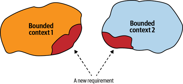
Figure 10-1. A change affecting multiple bounded contexts
Changes that invalidate the bounded contexts’ boundaries typically occur when the business domain is not well known or the business requirements change frequently. As you learned in Chapter 1, both volatility and uncertainty are the properties of core subdomains, especially at the early stages of implementation. We can use it as a heuristic for designing bounded context boundaries.
Broad bounded context boundaries, or those that encompass multiple subdomains, make it safer to be wrong about the boundaries or the models of the included subdomains. Refactoring logical boundaries is considerably less expensive than refactoring physical boundaries. Hence, when designing bounded contexts, start with wider boundaries. If required, decompose the wide boundaries into smaller ones as you gain domain knowledge.
This heuristic applies mainly to bounded contexts encompassing core subdomains, as both generic and supporting subdomains are more formularized and much less volatile. When creating a bounded context that contains a core subdomain, you can protect yourself against unforeseen changes by including other subdomains that the core subdomain interacts with most often. This can be other core subdomains, or even supporting and generic subdomains, as shown in Figure 10-2.
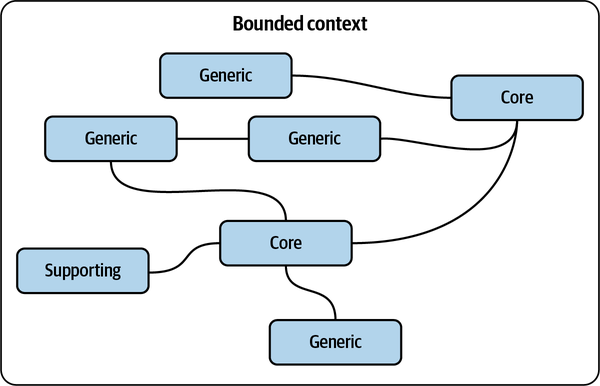
Figure 10-2. Wide bounded context boundaries
Business Logic Implementation Patterns
In Chapters 5–7, where we discussed
With all of this in mind, an effective heuristic for choosing the appropriate business logic implementation pattern is to ask the following questions:
-
Does the subdomain track money or other monetary transactions or have to provide a consistent audit log, or is deep analysis of its behavior required by the business? If so, use the event-sourced domain model. Otherwise...
-
Is the subdomain’s business logic complex? If so, implement a domain model. Otherwise...
-
Does the subdomain include complex data structures? If so, use the active record pattern. Otherwise...
-
Implement a transaction script.
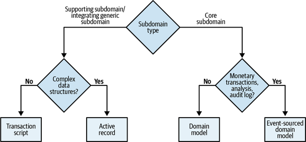
Figure 10-3. Decision tree for business logic implementation pattern
We can use another heuristic to define the difference between complex and simple business logic. The line between these two types of business logic is not terribly sharp, but it’s useful. In general, complex business logic includes complicated business rules, invariants, and algorithms. A simple approach mainly revolves around validating the inputs. Another heuristic for evaluating complexity concerns the complexity of the ubiquitous language itself. Is it mainly describing CRUD operations, or is it describing more complicated business processes and rules?
Deciding on the business logic implementation pattern according to the complexity of the business logic and its data structures is a way to validate your assumptions about the subdomain type. Suppose you consider it to be a core subdomain, but the best pattern is active record or transaction script. Or suppose what you believe is a supporting subdomain requires a domain model or an event-sourced domain model; in this case, it’s an excellent opportunity to revisit your assumptions about the subdomain and business domain in general. Remember, a core subdomain’s competitive advantage is not necessarily technical.
Architectural Patterns
Knowing the intended business logic implementation pattern makes choosing an architectural pattern straightforward:
- The event-sourced domain model requires CQRS.Otherwise, the system will be extremely limited in its data querying options, fetching a single instance by its ID only.
- The domain model requires the ports & adaptersarchitecture. Otherwise, the layered architecture makes it hard to make aggregates and value objects ignorant of persistence.
- The Active record pattern is best accompanied by alayered architecture with the additional application (service) layer. This is for the logic controlling the active records.
- The transaction script pattern can be implemented with a minimal layered architecture,consisting of only three layers.
The only exception to the preceding heuristics is the CQRS pattern. CQRS can be beneficial not only for the event-sourced domain model, but also for any other pattern if the subdomain requires representing its data in multiple persistent models.
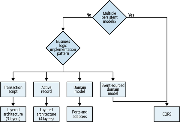
Figure 10-4. Architectural pattern decision tree
Testing Strategy
The knowledge of both the business logic implementation
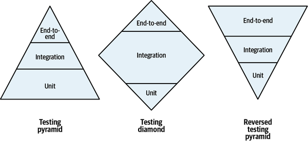
Figure 10-5. Testing strategies
The difference between the testing strategies in the figure is their emphasis on the different types of tests: unit, integration, and end-to-end. Let’s analyze each strategy and the context in which each pattern should be used.
Testing Pyramid
The classic testing pyramid emphasizes unit tests, fewer integration tests,
Testing Diamond
Reversed Testing Pyramid
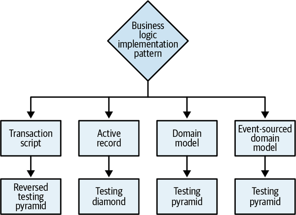
Figure 10-6. Testing strategy decision tree
Tactical Design Decision Tree
The business logic patterns, architectural patterns, and
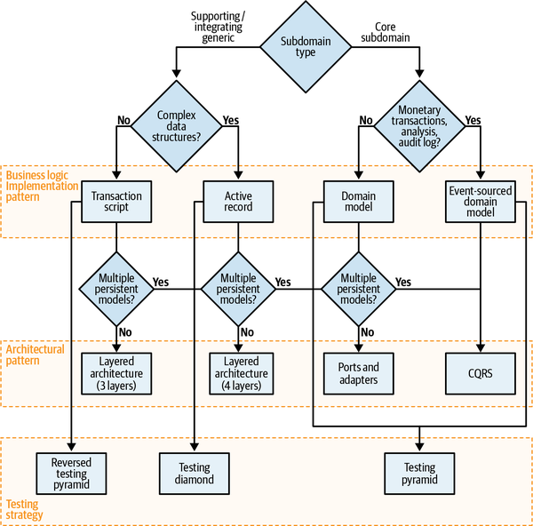
Figure 10-7. Tactical design decision tree
As you can see, identifying subdomains types and following the decision tree gives you a solid starting point for making the essential design decisions. That said, it’s important to reiterate that these are heuristics, not hard rules. There is an exception to every rule, let alone heuristics, that by definition are not intended to be correct in 100% of the cases.
The decision tree is based on my preference to use the simple tools, and resort to the advanced patterns—domain model, event-sourced domain model, CQRS, and so on—only when absolutely necessary. On the other hand, I’ve met teams that have a lot of experience implementing the event-sourced domain model and therefore use it for all their subdomains. For them it’s simpler than using different patterns. Can I recommend this approach to everyone? Of course not. In the companies I have worked for or consulted, the heuristics-based approach was more efficient than using the same solution for every problem.
At the end of the day, it depends on your specific context. Use the decision tree illustrated in Figure 10-7, and the design heuristics it is based on, as guiding principles, but not as a replacement for critical thinking. If you find that alternative heuristics fit you better, feel free to alter the guiding principles or build your own decision tree altogether.
Conclusion
This chapter connected Parts I and II of the book to a heuristic-based decision framework. You learned how to apply the knowledge of the business domain and its subdomains to drive technical decisions: choosing safe bounded context boundaries, modeling the application’s business logic, and determining the architectural pattern needed to orchestrate the interactions of each bounded context’s internal components. Finally, we took a detour into a different topic that is often a subject of passionate arguments—what kind of test is more important—and used the same framework to prioritize the different tests according to the business domain.
Making design decisions is important, but even more so is to verify the decisions’ validity over time. In the next chapter, we will shift our discussion to the next phase of the software design lifecycle: the evolution of design decisions.
Exercises
-
Assume you are implementing WolfDesk’s (see Preface) ticket lifecycle management system. It’s a core subdomain that requires deep analysis of its behavior so that the algorithm can be further optimized over time. What would be your initial strategy implementing the business logic and the component’s architecture? What would be your testing strategy?
-
What would be your design decisions for WolfDesk’s support agents’ shift management module?
-
To ease the process of managing agents’ shifts, you want to use an external provider of public holidays for different geographical regions. The process works by periodically calling the external provider and fetching the dates and names of forthcoming public holidays. What business logic and architectural patterns would you use to implement the integration? How would you test it?
-
Based on your experience, what other aspects of the software development process can be included in the heuristics-based decision tree presented in this chapter?
1 Gigerenzer, G., Todd, P. M., & ABC Research Group (Research Group, Max Planck Institute, Germany). (1999). Simple Heuristics That Make Us Smart. New York: Oxford University Press.
2 Chapter 11 is dedicated to the interplay between bounded contexts and microservices.
Chapter 11. Evolving Design Decisions
In the modern, fast-paced world we inhabit, companies cannot afford to be lethargic.
Changes in Domains
- Core
- Activities the company is performing differently from its competitors to gain a competitive advantage
- Supporting
- Things the company is doing differently from its competitors, but that do not provide a competitive edge
- Generic
- Things all companies do in the same way
In the previous chapters, you saw that the type of subdomain at play affects strategic and tactical design decisions:
-
How to design the bounded contexts’ boundaries
-
How to orchestrate integration between the contexts
-
Which design patterns to use to accommodate the complexity of the business logic
To design software that is driven by the business domain’s needs, it’s crucial to identify the business subdomains and their types. However, that’s not the whole story. It’s equally important to be alert to the evolution of the subdomains. As an organization grows and evolves, it’s not unusual for some of its subdomains to morph from one type to another. Let’s look at some examples of such changes.
Core to Generic
One day, another company—DeliverIT—disrupts the delivery industry. It claims it has solved the “traveling salesman” problem and provides path optimization as a service. Not only is DeliverIT’s optimization more advanced, it is offered at a fraction of the price that it costs BuyIT to perform the same task.
From BuyIT’s perspective, once DeliverIT’s solution became available as an off-the-shelf product, its core subdomain turned into a generic subdomain. As a result, the optimal solution became available to all of BuyIT’s competitors. Without massive investments in research and development, BuyIT can no longer gain a competitive advantage in the path optimization subdomain. What was previously considered a competitive advantage for BuyIT has become a commodity available to all of its competitors.
Generic to Core
BuyIT’s decision to replace the off-the-shelf solution with its own implementation has turned inventory management from a generic subdomain into a core subdomain: successful implementation of the functionality will provide BuyIT additional competitive advantage over its competitors—the competitors will remain “stuck” with the generic solution and will not be able to use the advanced demand prediction algorithms invented and developed by BuyIT.
A real-life textbook example of a company turning a generic subdomain into a core subdomain is Amazon. Like all service providers, Amazon needed an infrastructure on which to run its services. The company was able to “reinvent” the way it managed its physical infrastructure and later even turned it into a profitable business: Amazon Web Services.
Supporting to Generic
However, a few years after BuyIT began implementing the in-house solution, an open source contracts management solution came out. The open source project implements the same functionality as the existing solution and has more advanced features, like OCR and full-text search. These additional features had been on BuyIT’s backlog for a long time but were never prioritized because of their low business impact. Hence, the company decides to ditch the in-house solution in favor of integrating the open source solution. In doing so, the document management subdomain turns from a supporting into a generic subdomain.
Supporting to Core
The typical symptom of such a transformation is the increasing complexity of the supporting subdomain’s business logic. Supporting subdomains, by definition, are simple, mainly resembling CRUD interfaces or ETL processes. However, if the business logic becomes more complicated over time, there should be a reason for the additional complexity. If it doesn’t affect the company’s profits, why would it become more complicated? That’s accidental business complexity. On the other hand, if it enhances the company’s profitability, it’s a sign of a supporting subdomain becoming a core subdomain.
Core to Supporting
Generic to Supporting
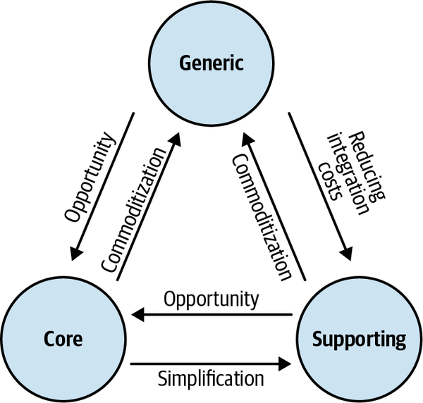
Figure 11-1. Subdomain type change factors
Strategic Design Concerns
Another integration pattern that is affected by such changes is the separate ways pattern.
From an implementation strategy standpoint, core and supporting subdomains differ in how they can be implemented. Supporting subdomains can be outsourced or used as “training wheels” for new hires. Core subdomains must be implemented in-house, as close as possible to the sources of domain knowledge. Therefore, when a supporting subdomain turns into a core subdomain, its implementation should be moved in-house. The same logic works the other way around. If a core subdomain turns into a supporting subdomain, it’s possible to outsource the implementation to let the in-house R&D teams concentrate on the core subdomains.
Tactical Design Concerns
If complicated rules and invariants are added to the business logic over time, the codebase will become increasingly complex as well. It will be painful to add the new functionality, as the design won’t support the new level of complexity. This “pain” is an important signal. Use it as a call to reassess the business domain and design choices.
The need for change in the implementation strategy is nothing to fear. It’s normal. We cannot foresee how a business will evolve down the road. We also cannot apply the most elaborate design patterns for all types of subdomains; that would be wasteful and ineffective. We have to choose the most appropriate design and evolve it when needed.
If the decision for how to model the business logic is made consciously, and you are aware of all the possible design choices and the differences between them, migrating from one design pattern to another is not that troublesome. The following subsections highlight a few examples.
Transaction Script to Active Record
At their core, both the transaction script and active record patterns
As a result, when working with data becomes challenging in a transaction script, refactor it into the active record pattern. Look for complicated data structures and encapsulate them in active record objects. Instead of accessing the database directly, use active records to abstract its model and structure.
Active Record to Domain Model
Start by identifying value objects. What data structures can be modeled as immutable objects? Look for the related business logic, and make it a part of the value objects as well.
Next, analyze the data structures and look for transactional boundaries. To ensure that all state-modifying logic is explicit, make all of the active records’ setters private so that they can only be modified from inside the active record itself. Obviously, expect the compilation to fail; however, the compilation errors will make it clear where the state-modifying logic resides. Refactor it into the active record’s boundaries. For example:
publicclassPlayer{publicGuidId{get;set;}publicintPoints{get;set;}}publicclassApplyBonus{...publicvoidExecute(GuidplayerId,bytepercentage){varplayer=_repository.Load(playerId);player.Points*=1+percentage/100.0;_repository.Save(player);}}
In the following code, you can see the first steps toward the transformation. The code won’t compile yet, but the errors will make it explicit where external components are controlling the object’s state:
publicclassPlayer{publicGuidId{get;privateset;}publicintPoints{get;privateset;}}publicclassApplyBonus{...publicvoidExecute(GuidplayerId,bytepercentage){varplayer=_repository.Load(playerId);player.Points*=1+percentage/100.0;_repository.Save(player);}}
In the next iteration, we can move that logic inside the active record’s boundary:
publicclassPlayer{publicGuidId{get;privateset;}publicintPoints{get;privateset;}publicvoidApplyBonus(intpercentage){this.Points*=1+percentage/100.0;}}
Finally, for each aggregate, identify its root, or the entry point for its public interface. Make the methods of all the other internal objects in the aggregate private and only callable from within the aggregate.
Domain Model to Event-Sourced Domain Model
Once you have a domain model with properly designed aggregate boundaries,
The most challenging aspect of refactoring a domain model into an event-sourced domain model is the history of the existing aggregates: migrating the “timeless” state into the event-based model. Since the fine-grained data representing all the past state changes is not there, you have to either generate past events on a best-effort basis or model migration events.
Generating Past Transitions
| lead-in | first-name | last-name | phone_number | status | last-contacted-on | order-placed-on | converted-on | followup-on |
|---|---|---|---|---|---|---|---|---|
| 12 | Shauna | Mercia | 555-4753 | converted | 2020-05-27T12:02:12.51Z | 2020-05-27T12:02:12.51Z | 2020-05-27T12:02:12.51Z | null |
We can assume from the business logic perspective that the instance of the aggregate has been initialized; then the person has been contacted, an order has been placed, and finally, since the status was “converted,” the payment for the order has been confirmed. The following set of events can represent all of these assumptions:
{"lead-id":12,"event-id":0,"event-type":"lead-initialized","first-name":"Shauna","last-name":"Mercia","phone-number":"555-4753"},{"lead-id":12,"event-id":1,"event-type":"contacted","timestamp":"2020-05-27T12:02:12.51Z"},{"lead-id":12,"event-id":2,"event-type":"order-submitted","payment-deadline":"2020-05-30T12:02:12.51Z","timestamp":"2020-05-27T12:02:12.51Z"},{"lead-id":12,"event-id":3,"event-type":"payment-confirmed","status":"converted","timestamp":"2020-05-27T12:38:44.12Z"}
When applied one by one, these events can be projected into the exact state representation as in the original system. The “recovered” events can be easily tested by projecting the state and comparing it to the original data.
However, it’s important to keep in mind the disadvantage of this approach. The goal of using event sourcing is to have a reliable, strongly consistent history of the aggregates’ domain events. When this approach is used, it’s impossible to recover the complete history of state transitions. In the preceding example, we don’t know how many times the sales agent has contacted the person, and therefore, how many “contacted” events we have missed.
Modeling Migration Events
The alternative approach is to acknowledge the lack of knowledge
{"lead-id":12,"event-id":0,"event-type":"migrated-from-legacy","first-name":"Shauna","last-name":"Mercia","phone-number":"555-4753","status":"converted","last-contacted-on":"2020-05-27T12:02:12.51Z","order-placed-on":"2020-05-27T12:02:12.51Z","converted-on":"2020-05-27T12:38:44.12Z","followup-on":null}
Organizational Changes
A trivial example of such change is growing development centers, as shown in Figure 11-2. Since a bounded context can be implemented by only one team, adding new development teams can cause the existing wider bounded context boundaries to split into smaller ones so that each team can work on its own bounded context.
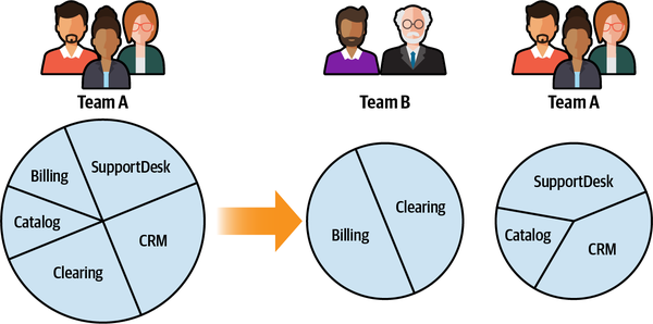
Figure 11-2. Splitting a wide bounded context to accommodate growing engineering teams
Moreover, the organization’s development centers are often located in different geographical locations. When the work on the existing bounded contexts is shifted to another location, it may negatively impact the teams’ collaboration. As a result, the bounded contexts’ integration patterns have to evolve accordingly, as described in the following scenarios.
Partnership to Customer–Supplier
The partnership pattern assumes there is strong communication
Customer–Supplier to Separate Ways
Domain Knowledge
Many times, the business domain’s complexity is implicit. Initially, everything seems simple and straightforward. The initial simplicity is often deceptive and it quickly morphs into complexity. As more functionality is added, more and more edge cases, invariants, and rules are discovered. Such insights are often disruptive, requiring rebuilding the model from the ground up, including the boundaries of the bounded contexts, aggregates, and other implementation details.
When new domain knowledge is discovered, it should be leveraged to evolve the design and make it more resilient. Unfortunately, changes in domain knowledge are not always positive: domain knowledge can be lost. As time goes by, documentation often becomes stale, people who were working on the original design leave the company, and new functionality is added in an ad hoc manner until, at one point, the codebase gains the dubious status of a legacy system. It’s vital to prevent such degradation of domain knowledge proactively. An effective tool for recovering domain knowledge is the EventStorming workshop, which is the topic of the next chapter.
Growth
Growth is a sign of a healthy system. When new functionality
A big ball of mud is a haphazardly structured, sprawling, sloppy, duct-tape-and-baling-wire, spaghetti-code jungle. These systems show unmistakable signs of unregulated growth, and repeated, expedient repair.
Brian Foote and Joseph Yoder1
The unregulated growth that leads to big balls of mud results from extending a software system’s functionality without re-evaluating its design decisions. Growth blows up the components’ boundaries, increasingly extending their functionality. It’s crucial to examine the effects of growth on design decisions, especially since many domain-driven design tools are all about setting boundaries: business building blocks (subdomains), model (bounded contexts), immutability (value objects), or consistency (aggregates).
The guiding principle for dealing with growth-driven complexity
When we discuss DDD in earlier chapters, we follow the process of first analyzing the business domain and its strategic components, designing the relevant models of the business domain, and then designing and implementing the models in code. Let’s follow the same script for dealing with growth-driven complexity.
Subdomains
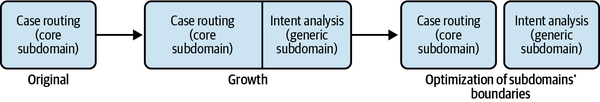
Figure 11-3. Optimizing subdomains’ boundaries to accommodate growth
If you are able to identify finer-grained subdomains of different types, this is an important insight that will allow you to manage the business domain’s essential complexity. The more precise the information about the subdomains and their types is, the more effective you will be at choosing technical solutions for each subdomain.
Identifying inner subdomains that can be extracted and made explicit is especially important for core subdomains. We should always aim to distill core subdomains as much as possible from all others so that we can invest our effort where it matters most from a business strategy perspective.
Bounded Contexts
In Chapter 3, you learned that the
Growth can also make existing implicit design issues explicit. For example, you may notice that a number of bounded contexts become increasingly “chatty” over time, unable to complete any operation without calling another bounded context. That can be a strong signal of an ineffective model and should be addressed by redesigning the bounded contexts’ boundaries to increase their autonomy.
Aggregates
The rule of thumb is to keep the aggregates as small as possible and include only objects that are required to be in a strongly consistent state by the business domain.
Conclusion
As Heraclitus famously said, the only constant in life is change. Businesses are no exception. To stay competitive, companies constantly strive to evolve and reinvent themselves. Those changes should be treated as first-class elements of the design process.
As the business domain evolves, changes to its subdomains must be identified and acted on in the system’s design. Make sure your past design decisions are aligned with the current state of the business domain and its subdomains. When needed, evolve your design to better match the current business strategy and needs.
It’s also important to recognize that changes in the organizational structure can affect communication and cooperation among teams and the ways their bounded contexts can be integrated. Learning about the business domain is an ongoing process. As more domain knowledge is discovered over time, it has to be leveraged to evolve strategic and tactical design decisions.
Finally, software growth is a desired type of change, but when it is not managed correctly, it may have disastrous effects on the system design and architecture. Therefore:
-
When a subdomain’s functionality is expanded, try to identify more finer-grained subdomain boundaries that will enable you to make better design decisions.
-
Don’t allow a bounded context to become a “jack of all trades.” Make sure the models encompassed by bounded contexts are focused to solve specific problems.
-
Make sure your aggregates’ boundaries are as small as possible. Use the heuristic of strongly consistent data to detect possibilities to extract business logic into new aggregates.
My final words of wisdom on the topic are to continuously check the different boundaries for signs of growth-driven complexity. Act to eliminate accidental complexities, and use domain-driven design tools to manage the business domain’s essential complexity.
Exercises
-
What kind of changes in bounded context integration are often caused by organizational growth?
-
Partnership to customer–supplier (conformist, anticorruption layer, or open-host service)
-
Anticorruption layer to open-host service
-
Conformist to shared kernel
-
Open-host service to shared kernel
-
-
Assume that the bounded contexts’ integration shifts from a conformist relationship to separate ways. What information can you deduce based on the change?
-
The development teams struggled to cooperate.
-
The duplicate functionality is either a supporting or a generic subdomain.
-
The duplicate functionality is a core subdomain.
-
A and B.
-
A and C.
-
-
What are the symptoms of a supporting subdomain becoming a core subdomain?
-
It becomes easier to evolve the existing model and implement the new requirements.
-
It becomes painful to evolve the existing model.
-
The subdomain changes at a higher frequency.
-
B and C.
-
None of the above.
-
-
What change results from discovering a new business opportunity?
-
A supporting subdomain turns into a core one.
-
A supporting subdomain turns into a generic one.
-
A generic subdomain turns into a core one.
-
A generic subdomain turns into a supporting one.
-
A and B.
-
A and C.
-
-
What change in the business strategy could turn one of WolfDesk’s (the fictitious company described in the Preface) generic subdomains into a core subdomain?
Chapter 12. EventStorming
In this chapter, we will take a break from discussing software design patterns and techniques. Instead, we will focus on a low-tech modeling process called EventStorming. This process brings together the core aspects of domain-driven design that we covered in the preceding chapters.
You will learn the EventStorming process, how to facilitate an EventStorming workshop, and how to leverage EventStorming to effectively share domain knowledge and build a ubiquitous language.
What Is EventStorming?
EventStorming is a low-tech activity for a group of people
Who Should Participate in EventStorming?
Just keep in mind that the goal of the workshop is to learn asmuch as possible in the shortest time possible. We invite key people to the workshop, and we don’t want to waste their valuable time.Alberto Brandolini, creator of the EventStorming workshop
Ideally, a diverse group of people should participate in the workshop. Indeed, anyone related to the business domain in question can participate: engineers, domain experts, product owners, testers, UI/UX designers, support personnel, and so on. As more people with different backgrounds are involved, more knowledge will be discovered.
Take care not to make the group too big, however. Every participant should be able to contribute to the process, but this can be challenging for groups of more than 10 participants.
What Do You Need for EventStorming?
- Modeling space
- First, you need a large modeling space. A whole wall coveredwith butcher paper makes the best modeling space, as shown inFigure 12-1. A large whiteboard can fit the purpose as well, but it has to be as big as possible—you will need all the modeling space you can get.
- Sticky notes
- Next, you need lots of sticky notes of different colors. The notes will be used to represent different concepts of the business domain, and every participant should be able to add them freely, so make sure you have enough colors and enough for everyone. The colors that are traditionally used for EventStorming are described in the next section. It’s best to stick to these conventions, if possible, to be consistent with all of the currently available EventStorming books and trainings.
- Markers
- You’ll also need markers that you can use to write on the sticky notes. Again, supplies shouldn’t be a bottleneck for knowledge sharing—there should be enough markers for all participants.
- Snacks
- A typical EventStorming session lasts about two to four hours, so bring some healthy snacks for energy replenishment.
- Room
- Finally, you need a spacious room. Ensure there isn’t a huge table in the middle that will prevent participants from moving freely and observing the modeling space. Also, chairs are a big no-no for EventStorming sessions. You want people to participate and share knowledge, not sit in a corner and zone out. Therefore, if possible, take the chairs out of the room.1
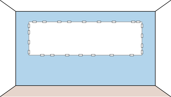
Figure 12-1. Modeling space for EventStorming
The EventStorming Process
An EventStorming workshop is usually conducted in 10 steps.
Step 1: Unstructured Exploration
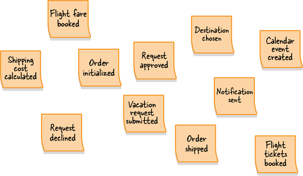
Figure 12-2. Unstructured exploration
During this step, all participants are grabbing a bunch of orange sticky notes, writing down whatever domain events come to mind, and sticking them to the modeling surface.
At this early stage, there is no need to worry about ordering events, or even about redundancy. This step is all about brainstorming the possible things that can happen in the business domain.
The group should continue generating domain events until the rate of adding new ones slows significantly.
Step 2: Timelines
Next, the participants go over the generated domain events and organize
The events should start with the “happy path scenario”: the flow that describes a successful business scenario.
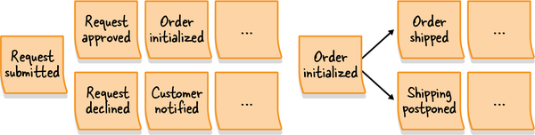
Figure 12-3. Flows of events
This step is also the time to fix incorrect events, remove duplicates, and of course, add missing events if necessary.
Step 3: Pain Points
Once you have the events organized in a timeline, use this broad
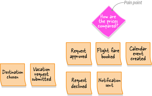
Figure 12-4. A diamond-shaped pink sticky note, which points to an aspect of the process that requires attention: missing domain knowledge about how the airfare prices are compared during the booking process
Of course, this step is not the only opportunity to track pain points. As a facilitator, be aware of the participants’ comments throughout the process. When an issue or a concern is raised, document it as a pain point.
Step 4: Pivotal Events
Once you have a timeline of events augmented with pain points,
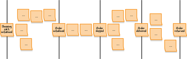
Figure 12-5. Pivotal events denoting context changes in the flow of events
Pivotal events are an indicator of potential bounded context boundaries.
Step 5: Commands
Whereas a domain event describes something that has already
-
Publish campaign
-
Roll back transaction
-
Submit order
Naturally, not all commands will have an associated actor. Therefore, add the actor information only where it’s obvious. In the next step we will augment the model with additional entities that can trigger commands.
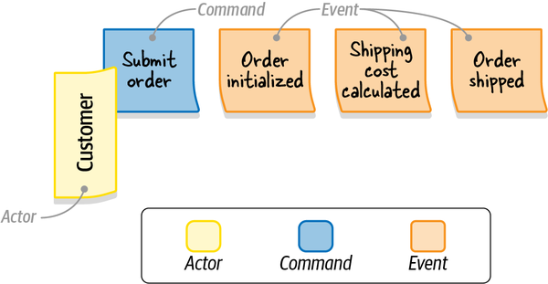
Figure 12-6. The “Submit Order” command, executed by the customer (actor) and followed by the “Order initialized,” “Shipping cost calculated,” and “Order shipped” events
Step 6: Policies
Almost always, some commands are added to the model but
An automation policy is a scenario in which an event triggers the execution of a command. In other words, a command is automatically executed when a specific domain event occurs.

Figure 12-7. An automation policy that triggers the “Ship Order” command when the “Shipment Approved” event is observed
If the command in question should be triggered only if some decision criteria is met, you can specify the decision criteria explicitly on the policy sticky note. For example, if you need to trigger the escalate command after the “complaint received” event, but only if the complaint was received from a VIP customer, you can explicitly state the “only for VIP customers” condition on the policy sticky.
If the events and commands are far apart, you can draw an arrow on the modeling surface to connect them.
Step 7: Read Models
A read model is the view of data within the domain that the actor
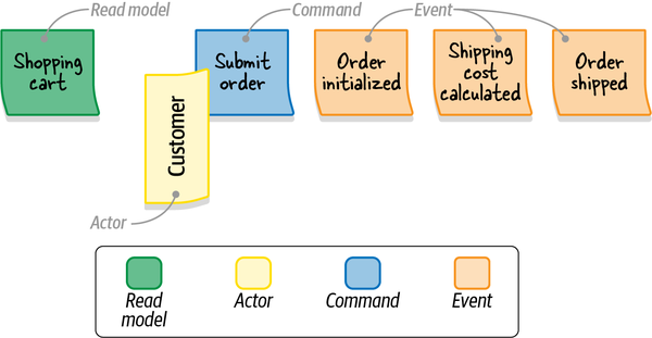
Figure 12-8. The view of the “Shopping cart” (read model) needed for the customer (actor) to make their decision to submit the order (command)
Step 8: External Systems
This step is about augmenting the model with external systems.
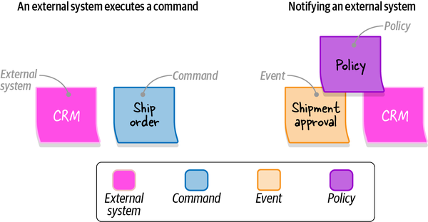
Figure 12-9. External system triggering execution of a command (left) and approval of the event being communicated to the external system (right)
By the end of this step, all commands should either be executed by actors, triggered by policies, or called by external systems.
Step 9: Aggregates
Once all the events and commands are represented, the participants
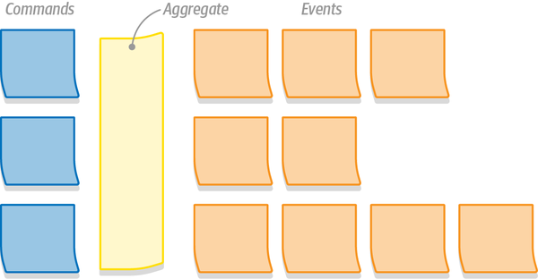
Figure 12-10. Commands and domain events organized in an aggregate
Step 10: Bounded Contexts
The last step of an EventStorming session is to look for aggregates
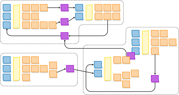
Figure 12-11. A possible decomposition of the resultant system into bounded contexts
Variants
In my experience, when introducing EventStorming in an organization I prefer to start by exploring the big picture of the business domain by following steps 1 (chaotic exploration) through 4 (pivotal events). The resultant model covers a wide range of the company’s business domain, builds a strong foundation for ubiquitous languages, and outlines possible boundaries for bounded contexts.
After gaining the big picture and identifying the different business processes, we continue to facilitate a dedicated EventStorming session for each relevant business process—this time, following all the steps to model the complete process.
At the end of a full EventStorming session, you will have a model describing the business domain’s events, commands, aggregates, and even possible bounded contexts. However, all of these are just nice bonuses. The real value of an EventStorming session is the process itself—the sharing of knowledge among different stakeholders, alignment of their mental models of the business, discovery of conflicting models, and, last but not least, formulation of the ubiquitous language.
The resultant model can be adopted as a basis for implementing an event-sourced domain model. The decision of whether to go that route or not depends on your business domain. If you decide to implement the event-sourced domain model, you have the bounded context boundaries, the aggregates, and of course, the blueprint of the required domain events.
When to Use EventStorming
- Build a ubiquitous language
- As the group cooperates in building the model of thebusiness process, they instinctively synchronize the terminology and start using the same language.
- Model the business process
- An EventStorming session is an effective way to build a model of the business process. Since it is based on DDD-oriented building blocks, it is also an effective way to discover the boundaries of aggregates and bounded contexts.
- Explore new business requirements
- You can use EventStorming to ensure that all the participants are on the same page regarding the new functionality and reveal edge cases not covered by the business requirements.
- Recover domain knowledge
- Over time, domain knowledge can get lost. This is especially acute in legacy systems that require modernization. EventStorming is an effective way to merge the knowledge held by each participant into a single coherent picture.
- Explore ways to improve an existing business process
- Having an end-to-end view of a business process provides the perspective needed to notice inefficiencies and opportunities to improve the process.
- Onboard new team members
- Facilitating an EventStorming session together with new team members is a great way to expand their domain knowledge.
In addition to when to use EventStorming, it’s important to mention when not to use it. EventStorming will be less successful when the business process you’re exploring is simple or obvious, such as following a series of sequential steps without any interesting business logic or complexity.
Facilitation Tips
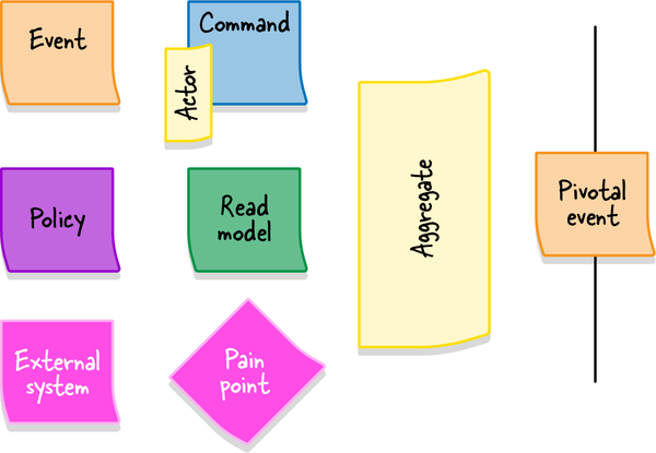
Figure 12-12. Legend depicting the various elements of the EventStorming process written on the corresponding sticky notes
Watch the Dynamics
As the workshop progresses, it’s important to track the energy of the group. If the dynamics are slowing down, see whether you can reignite the process by asking questions or whether it’s time to advance to the next stage of the workshop.
Remember that EventStorming is a group activity, so ensure that it is handled as such. Make sure everyone has a chance to participate in the modeling and the discussion. If you notice that some participants are shying away from the group, try to involve them in the process by asking questions about the current state of the model.
EventStorming is an intense activity, and at some point, the group will need a break. Don’t resume the session until all the participants are back in the room. Resume the process by going through the current state of the model to return the group to a collaborative modeling mood.
Remote EventStorming
EventStorming was invented as a low-tech activity in which people
In addition, my experience shows that remote EventStorming sessions are more effective with a smaller number of participants. While as many as 10 people can attend an in-person EventStorming session, I prefer to limit online sessions to five participants. When you need more participants to contribute their knowledge, you can facilitate multiple sessions, and afterward compare and merge the resultant models.
When the situation allows, return to in-person EventStorming.
Conclusion
EventStorming is a collaboration-based workshop for modeling business processes. Apart from the resultant models, its primary benefit is knowledge sharing. By the end of the session, all the participants will synchronize their mental models of the business process and take the first steps toward using a ubiquitous language.
EventStorming is like riding a bicycle. It’s much easier to learn by doing it than to read about it in a book. Nevertheless, the workshop is fun and easy to facilitate. You don’t need to be an EventStorming black belt to get started. Just facilitate the session, follow the steps, and learn during the process.
Exercises
-
Who should be invited to an EventStorming session?
-
Software engineers
-
Domain experts
-
QA engineers
-
All stakeholders having knowledge of the business domain that you want to explore
-
-
When is it a good opportunity to facilitate an EventStorming session?
-
To build a ubiquitous language.
-
To explore a new business domain.
-
To recover lost knowledge of a brownfield project.
-
To introduce new team members.
-
To discover ways to optimize the business process.
-
All of the above answers are correct.
-
-
What outcomes can you expect from an EventStorming session?
-
A better shared understanding of the business domain
-
A strong foundation for a ubiquitous language
-
Uncovered white spots in the understanding of the business domain
-
An event-based model that can be used to implement a domain model
-
All of the above, but depending on the session’s purpose
-
1 Of course, that’s not a hard rule. Leave a few chairs if some of the participants find it hard to be on their feet for so long.
Chapter 13. Domain-Driven Design in the Real World
We have covered domain-driven design tools for analyzing business domains,
Another common misconception about DDD is that it’s an all-or-nothing proposition—either you apply every tool the methodology has to offer, or it’s not domain-driven design. That’s not true. It might seem overwhelming to come to grips with all of these concepts, let alone implement them in practice. Luckily, you don’t have to apply all of the patterns and practices to gain value from domain-driven design. This is especially true for brownfield projects, where it’s practically impossible to introduce all the patterns and practices in a reasonable time frame.
In this chapter, you will learn strategies for applying domain-driven design tools and patterns in the real world, including on brownfield projects and in less-than-ideal environments.
Strategic Analysis
Understand the Business Domain
-
What is the organization’s business domain(s)?
-
Who are its customers?
-
What service, or value, does the organization provide to customers?
-
What companies or products is the organization competing with?
Answering these questions will give you a bird’s-eye view of the company’s high-level goals. Next, “zoom in” to the domain and look for the business building blocks the organization employs to achieve its high-level goals: the subdomains.
A good initial heuristic is the company’s org chart: its departments and other organizational units. Examine how these units cooperate to allow the company to compete in its business domain.
Core subdomains
-
Does the company have a “secret sauce” that its competitors lack? For example, intellectual property, such as patents and algorithms designed in-house?
-
Keep in mind that the competitive advantage, and thus the core subdomains, are not necessarily technical. Does the company possess a nontechnical competitive advantage? For example, the ability to hire top-level personnel, produce a unique artistic design, and so on?
Another powerful yet unfortunate heuristic for core subdomains is identifying the worst-designed software components—those big balls of mud that all engineers hate but the business is unwilling to rewrite from scratch because of the accompanying business risk. The key here is that the legacy system cannot be replaced with a ready-made system—it would be a generic subdomain—and any modification to it entails business risks.
Generic subdomains
Supporting subdomains
For supporting subdomains, look for the remaining software components
You don’t have to identify all of the core subdomains. It won’t be practical or even possible to do so, even for a medium-sized company. Instead, identify the overall structure, but pay closer attention to the subdomains that are most relevant to the software systems you are working on.
Explore the Current Design
The characteristic property to look for is the components’ decoupled lifecycles. Even if the subsystems are managed in the same source control repository (mono-repo) or if all the components reside in a single monolithic codebase, check which can be evolved, tested, and deployed independently from the others.
Evaluate the tactical design
Does the solution fit the complexity of the problem? Are there areas where more elaborate design patterns are needed? Conversely, are there any subdomains where it’s possible to cut corners or use existing, off-the-shelf solutions? Use this information to make smarter strategic and tactical decisions.
Evaluate the strategic design
Finally, analyze the resultant context map and evaluate the architecture from a domain-driven design perspective. Are there suboptimal strategic design decisions? For example:
-
Multiple teams working on the same high-level component
-
Duplicate implementations of core subdomains
-
Implementation of a core subdomain by an outsourced company
-
Friction because of frequently failing integration
-
Awkward models spreading from external services and legacy systems
Modernization Strategy
The “big rewrite” endeavors, in which the engineers are trying
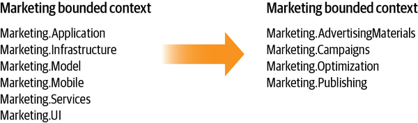
Figure 13-1. Reorganizing the bounded context’s modules to reflect the business subdomains’ boundaries rather than technical implementation patterns
Adjusting the system’s modules is a relatively safe form of refactoring. You are not modifying the business logic, just repositioning the types in a more well-organized structure. That said, ensure that references by full type names, such as the dynamic loading of libraries, reflection, and so on, are not breaking.
In addition, keep track of the subdomains’ business logic implemented in different codebases; stored procedures in a database, serverless functions, and so on. Make sure to introduce the new boundaries in those platforms as well. For instance, if some of the logic is handled in the database’s stored procedures, either rename the procedures to reflect the module they belong to or introduce a dedicated database schema and relocate the stored procedures.
Strategic Modernization
As we discussed in Chapter 10, it can be risky
Questions to ask yourself:
-
Are multiple teams working on the same codebase? If so, decouple the development lifecycles by defining bounded contexts for each team.
-
Are conflicting models being used by the different components? If so, relocate the conflicting models into separate bounded contexts.
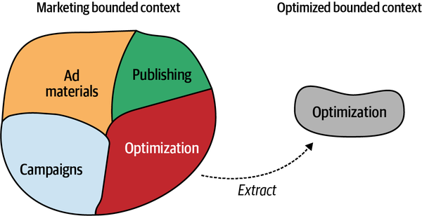
Figure 13-2. Extracting a bounded context by turning a logical boundary into a physical boundary
When the minimum required bounded contexts are in place, examine
Pay attention to problems that the context integration patterns can address:
- Customer–supplier relationships
- As we discussed inChapter 11, organizationalgrowth can invalidate prior communication and collaboration patterns. Look for components designed for a partnership relationship of multiple engineering teams, but where the partnership is no longer sustainable. Refactor to the appropriate type of customer–supplier relationship (conformist, anticorruption layer, or open-host service).
- Anticorruption layer
- Anticorruption layers can be useful for protecting boundedcontexts from legacy systems, especially, when legacy systems are using inefficient models that tend to spread into downstream components.
- Another common use case for implementing an anticorruption layer is to protect a bounded context from frequent changes in the public interfaces of an upstream service it uses.
- Open-host service
- If changes in the implementation details of one component often ripplethrough the system and affect its consumers, consider making it an open-host service: decouple its implementation model from the public API it exposes.
- Separate ways
- Especially in large organizations, you may encounter frictionamong engineering teams resulting from having to collaborate and co-evolve a shared functionality. If the “apple of discord” functionality is not business critical—that is, it’s not a core subdomain—the teams can go their separate ways and implement their own solutions, eliminating the source of friction.
Tactical Modernization
Cultivate a Ubiquitous Language
Strangler pattern

Figure 13-3. A strangler fig growing on top of its host tree (source: https://unsplash.com/photos/y_l5tep9wxI)
The strangler migration pattern is based on the same growth dynamic as the tree the pattern is named after. The idea is to create a new bounded context—the strangler—use it to implement new requirements, and gradually migrate the legacy context’s functionality into it. At the same time, except for hotfixes and other emergencies, the evolution and development of the legacy bounded context stops. Eventually, all functionality is migrated to the new bounded context—the strangler— and following the analogy, leading to the death of the host—the legacy codebase.
Usually, the strangler pattern is used in tandem with the façade pattern:
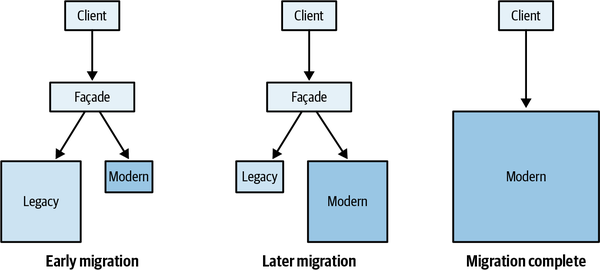
Figure 13-4. The façade layer forwarding the request based on the status of migrating the functionality from the legacy to the modernized system; once the migration is complete, both the façade and the legacy system are removed
Contrary to the principle that each bounded context is a separate subsystem, and thus cannot share its database with other bounded contexts, the rule can be relaxed when implementing the strangler pattern. Both the modernized and the legacy contexts can use the same database for the sake of avoiding complex integration between the contexts, which in many cases can entail distributed transactions—both contexts have to work with the same data, as shown in Figure 13-5.
The condition for bending the one-database-per-bounded-context rule is that eventually, and better sooner than later, the legacy context will be retired, and the database will be used exclusively by the new implementation.
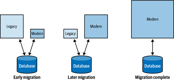
Figure 13-5. Both the legacy and the modernized systems temporarily working with the same database
An alternative to strangler-based migration is modernizing the legacy codebase in place, also called refactoring.
Refactoring tactical design decisions
First, small incremental steps are safer than a big rewrite. Therefore, don’t refactor a transaction script or active record straight to an event-sourced domain model. Instead, take the intermediate step of designing state-based aggregates. Invest the effort in finding effective aggregate boundaries. Ensure that all related business logic resides within those boundaries. Going from state-based to event-sourced aggregates will be orders of magnitude safer than discovering wrong transactional boundaries in an event-sourced aggregate.
Second, following the same reasoning of taking small incremental steps, refactoring to a domain model doesn’t have to be an atomic change. Instead, you can gradually introduce the elements of the domain model pattern.
Start by looking for possible value objects. Immutable objects can significantly reduce the solution’s complexity, even if you are not using a full-blown domain model.
As we discussed in Chapter 11, refactoring active records into aggregates doesn’t have to be done overnight. It can be done in gradual steps. Start by gathering the related business logic. Next, analyze the transactional boundaries. Are there decisions that require strong consistency but operate on eventually consistent data? Or conversely, does the solution enforce strong consistency where eventual consistency would suffice? When analyzing the codebase, don’t forget that these decisions are driven by business, not technology, concerns. Only after a thorough analysis of the transactional requirements should you design the aggregate’s boundaries.
Finally, when necessary as you’re refactoring legacy systems, protect the new codebase from old models using an anticorruption layer, and protect the consumers from changes in the legacy codebase by implementing an open-host service and exposing a published language.
Pragmatic Domain-Driven Design
As long as you analyze your business domain and its strategy, look for effective models to solve particular problems, and most importantly, make design decisions based on the business domain’s needs: that’s domain-driven design!
It’s worth reiterating that domain-driven design is not about aggregates or value objects. Domain-driven design is about letting your business domain drive software design decisions.
Selling Domain-Driven Design
Selling is hard, and personally, I hate selling. That said, if you think about it, designing software is selling. We are selling our ideas to the team, to management, or to customers. However, a methodology that covers such a wide range of design decision aspects, and even reaches outside the engineering zone to involve other stakeholders, can be extremely hard to sell.
Management support is essential for making any considerable changes in an organization. However, unless the top-level managers are already familiar with domain-driven design or are willing to invest time to learn the business value of the methodology, it’s not top of mind for them, especially because of a seemingly large shift in the engineering process that DDD entails. Fortunately, however, it doesn’t mean you can’t use domain-driven design.
Undercover Domain-Driven Design
Let’s see how to incorporate DDD into your day-to-day job without making much ado about it.
Ubiquitous language
The use of a ubiquitous language is the cornerstone practice of domain-driven design. It is essential for domain knowledge discovery, communication, and effective solution modeling.
Luckily, this practice is so trivial that it’s borderline common sense. Listen carefully to the language the stakeholders use when they speak about the business domain. Gently steer the terminology away from technical jargon and toward its business meaning.
Look for inconsistent terms and ask for clarifications. For example, if there are multiple names for the same thing, look for the reason. Are those different models intertwined in the same solution? Look for contexts and make them explicit. If the meaning is the same, follow common sense and ask for one term to be used.
Also, communicate with domain experts as much as possible. These efforts shouldn’t necessarily require formal meetings. Watercoolers and coffee breaks are great communication facilitators. Speak with the domain experts about the business domain. Try using their language. Look for difficulties in understanding and ask for clarifications. Don’t worry—domain experts are usually happy to collaborate with engineers who are sincerely interested in learning about the problem domain!
Most importantly, use the ubiquitous language in your code and all project-related communication. Be patient. Changing the terminology that has been used in an organization for a while will take time, but eventually, it will catch on.
Bounded contexts
-
Why is it better to design problem-oriented models instead of a single model for all use cases? Because “all-in-one” solutions are rarely effective for anything.
-
Why can’t a bounded context host conflicting models? Because of the increased cognitive load and solution complexity.
-
Why is it a bad idea for multiple teams to work on the same codebase? Because of friction and hindered collaboration between the teams.
Use the same reasoning for bounded context integration patterns: make sure you understand the problem each pattern is supposed to solve.
Tactical design decisions
-
Why are explicit transactional boundaries important? To protect the consistency of the data.
-
Why can’t a database transaction modify more than one instance of an aggregate? To ensure that the consistency boundaries are correct.
-
Why can’t an aggregate’s state be modified directly by an external component? To ensure that all the related business logic is colocated and not duplicated.
-
Why can’t we offload some of the aggregate’s functionality to a stored procedure? To make sure that no logic is duplicated. Duplicated logic, especially in logically and physically distant components of a system, tends to go out of sync and lead to data corruption.
-
Why should we strive for small aggregate boundaries? Because wide transactional scope will both increase the complexity of the aggregate and negatively impact the performance.
-
Why, instead of event sourcing, can’t we just write events to a logfile? Because there are no long-term data consistency guarantees.
Speaking of event sourcing, when the solution calls for an event-sourced domain model, implementation of this pattern might be hard to sell. Let’s take a look at a Jedi mind trick that can help with this.
Event-sourced domain model
Talk to domain experts. Show them the state- and event-based models. Explain the differences and the advantages offered by event sourcing, especially with regard to the dimension of time. More often than not, they will be ecstatic with the level of insight it provides and will advocate event sourcing themselves.
Conclusion
In this chapter, you learned various techniques for leveraging domain-driven design tools in real-life scenarios: when working on brownfield projects and legacy codebases, and not necessarily with a team of DDD experts.
As in greenfield projects, always start by analyzing the business domain. What are the company’s goals and its strategy for achieving them? Use the organizational structure and existing software design decisions to identify the organization’s subdomains and their types. With this knowledge, plan the modernization strategy. Look for pain points. Look to gain the most business value. Modernize legacy code either by refactoring or by replacing the relevant components. Either way, do it gradually. Big rewrites entail more risk than business value!
Finally, you can use domain-driven design tools even if DDD is not widely adopted in your organization. Use the right tools, and when discussing them with colleagues, always use the logic and principles behind each pattern.
Exercises
-
Assume you want to introduce domain-driven design tools and practices to a brownfield project. What is going to be your first step?
-
Refactor all business logic to the event-sourced domain model.
-
Analyze the organization’s business domain and its strategy.
-
Improve the system’s components by ensuring that they follow the principles of proper bounded contexts.
-
It’s impossible to use domain-driven design in a brownfield project.
-
-
In what ways does the strangler pattern contradict some of the core principles of domain-driven design during the migration process?
-
Multiple bounded contexts are using a shared database.
-
If the modernized bounded context is a core subdomain, its implementation gets duplicated in the old and the new implementations.
-
Multiple teams are working on the same bounded context.
-
A and B.
-
-
Why is it generally not a good idea to refactor active-record-based business logic straight into the event-sourced domain model?
-
A state-based model makes it easier to refactor aggregates’ boundaries during the learning process.
-
It’s safer to introduce big changes gradually.
-
A and B.
-
None of the above. It’s reasonable to refactor even a transaction script straight into an event-sourced domain model.
-
-
When you’re introducing the aggregate pattern, your team asks why the aggregate can’t just reference all the possible entities and thus make it possible to traverse the whole business domain from one place. How do you answer them?
Part IV. Relationships to Other Methodologies and Patterns
So far in this book you’ve learned how to use domain-driven design to design software solutions according to an organization’s business strategy and needs. We saw how to apply DDD tools and practices to make sense of the business domain, design the boundaries of the system’s components, and implement the business logic.
Domain-driven design covers a lot of the software development lifecycle, but it can’t cover all of software engineering. Other methodologies and tools have their roles. In Part IV, we will discuss DDD in relation to other methodologies and patterns:
-
It’s no secret that domain-driven design gained most of its traction due to the popularity of the microservices-based architectural style. In Chapter 14, we will explore the interplay between microservices and domain-driven design and how the two approaches complement each other.
-
The event-driven architecture is a popular method of architecting scalable, performant, and resilient distributed systems. In Chapter 15, you will learn the principles of event-driven architecture and how to leverage DDD to design effective asynchronous communication.
-
Chapter 16 concludes the book with effective modeling in the context of data analytics. You will learn about the predominant data management architectures, data warehouses and data lakes, and how their shortcomings are addressed by the data mesh architecture. We will also analyze and discuss how DDD and the data mesh architecture are based on the same design principles and goals.
Chapter 14. Microservices
In the mid-2010s, microservices took the software engineering industry by storm.
Historically, microservices are often associated with DDD, especially with the bounded context pattern. Many people even use the terms bounded context and microservices interchangeably. But are they really the same thing? This chapter explores the relationship between domain-driven design methodology and the microservices architectural pattern. You will learn the interplay between the patterns, and more importantly, how you can leverage DDD to design effective microservices-based systems.
Let’s start with the basics and define what exactly are services and microservices.
What Is a Service?
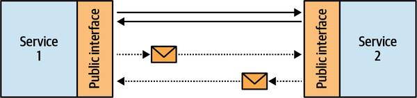
Figure 14-1. Communication between services
Randy Shoup likens a service’s interface to a front door.
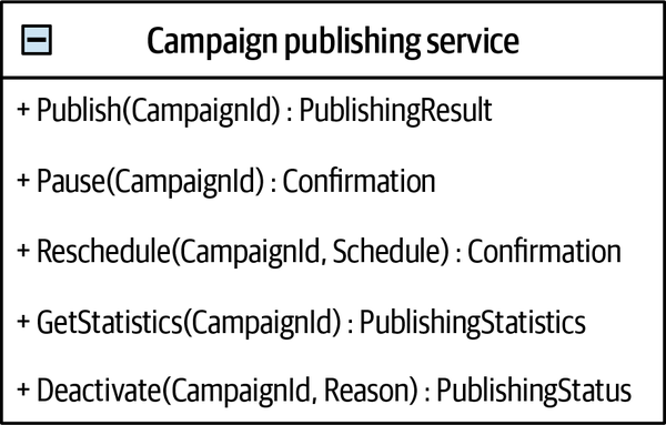
Figure 14-2. A service’s public interface
This takes us to the definition of microservice.
What Is a Microservice?
The definition of a microservice is surprisingly simple. Since a service
Having a micro-public interface makes it easier to understand both the function of a single service and its integration with other system components. Reducing a service’s functionality also limits its reasons for change and makes the service more autonomous for development, management, and scale.
In addition, it explains the practice of microservices not exposing their databases. Exposing a database, making it a part of the service’s front door, would make its public interface huge. For example, how many different SQL queries can you execute on a relational database? Since SQL is quite a flexible language, the likely estimate would be infinity. Hence, microservices encapsulate their databases. The data can only be accessed through a much more compact, integration-oriented public interface.
Method as a Service: Perfect Microservices?
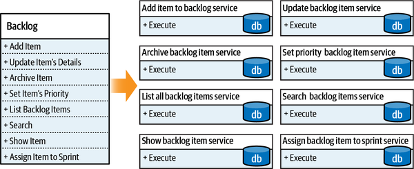
Figure 14-3. Naïve decomposition
Since these are well-behaved microservices, each encapsulates its database. No one service is allowed to access another service’s database directly; only through its public interface. But currently, there is no public interface for that. The services have to work together and synchronize the changes each service is applying. As a result, we need to expand the services’ interfaces to account for these integration-related concerns. Furthermore, when visualized, the integrations and data flow between the resultant services resemble a typical distributed big ball of mud, as shown in Figure 14-4.
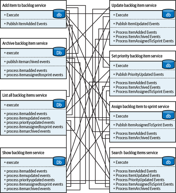
Figure 14-4. Integration complexity
Paraphrasing Randy Shoup’s metaphor, by decomposing the system to such fine-grained services, we definitely minimized the services’ front doors. However, to implement the overarching system’s functionality, we had to add enormous “staff only” entrances to each service. Let’s see what we can learn from this example.
Design Goal
Following the simplistic decomposition heuristic of having each service
-
A set of connected things or devices that operate together
-
A set of computer equipment and programs used together for a particular purpose
Hence, a system cannot be built out of independent components. In a proper microservices-based system, however decoupled, the services still have to be integrated and communicate with each other. Let’s take a look at the interplay between the complexity of individual microservices and the complexity of the overarching system.
System Complexity
There is much more to the subject of complexity than simply attempting to minimize the local complexity of each part of a program.A much more important type of complexity is global complexity: the complexity of the overall structure of a program or system (i.e., the degree of association or interdependence among the major pieces of a program).
It’s surprisingly easy to reduce global complexity to a minimum. All we have to do is eliminate any interactions between the system’s components—that is, implement all functionality in one monolithic service. As we’ve seen earlier, this strategy may work in certain scenarios. In others, it may lead to the dreaded big ball of mud: probably the highest possible level of local complexity.
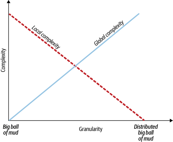
Figure 14-5. Service granularity and system complexities
To design a proper microservices-based system, we have to optimize both global and local complexities. Setting the design goal of optimizing either one individually is a local optima. The global optima balances both complexities. Let’s see how the notion of micro-public interfaces lends itself to balancing global and local complexities.
Microservices as Deep Services
A module in a software system, or any system, for that matter, is defined by its function and logic.
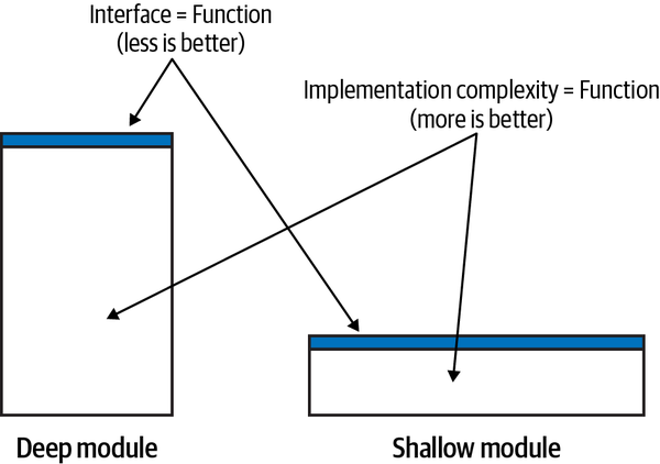
Figure 14-6. Deep modules
According to this model, effective modules are deep: a simple public interface encapsulates complex logic. Ineffective modules are shallow: a shallow module’s public interface encapsulates much less complexity than a deep module. Consider the method in the following listing:
intAddTwoNumbers(inta,intb){returna+b;}
This is the extreme case of a shallow module: the public interface (the method’s signature) and its logic (the methods) are exactly the same. Having such a module introduces extraneous “moving parts,” and thus, instead of encapsulating complexity, it adds accidental complexity to the overarching system.
Microservices as Deep Modules
Apart from different terminology, the notion of deep modules differs
From a system complexity standpoint, a deep module reduces the system’s global complexity, while a shallow module increases it by introducing a component that doesn’t encapsulate its local complexity.
Shallow services are also the reason why so many microservices-oriented projects fail. The mistaken definitions of a microservice as a service having no more than X lines of code, or as a service that should be easier to rewrite than to modify, concentrate on the individual service while missing the most important aspect of the architecture: the system.
The threshold upon which a system can be decomposed into microservices is defined by the use cases of the system that the microservices are a part of. If we decompose a monolith into services, the cost of introducing a change goes down. It is minimized when the system is decomposed into microservices. However, if you keep decomposing past the microservices threshold, the deep services will become more and more shallow. Their interfaces will grow back up. This time, due to integration needs, the cost of introducing a change will go up as well, and the overall system’s architecture will turn into the dreaded distributed big ball of mud. This is depicted in Figure 14-7.
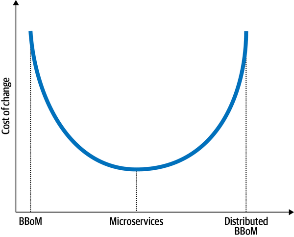
Figure 14-7. Granularity and cost of change
Now that we’ve learned what microservices are, let’s take a look at how domain-driven design can help us find the boundaries of deep services.
Domain-Driven Design and Microservices’ Boundaries
Bounded Contexts
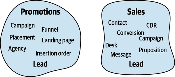
Figure 14-8. Bounded contexts
For simplicity’s sake, let’s assume there are no other conflicting models in the system besides Lead. This makes the resultant bounded contexts naturally wide—each bounded context can contain multiple subdomains. The subdomains can be moved from one bounded context to another one. As long as the subdomains do not imply conflicting models, all the alternative decompositions in Figure 14-9 are perfectly valid bounded contexts.
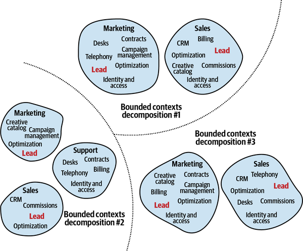
Figure 14-9. Alternative decompositions to bounded contexts
The different decompositions to bounded contexts attribute different requirements, such as different teams’ sizes and structures, lifecycle dependencies, and so on. But can we say that all the valid bounded contexts in this example are necessarily microservices? No. Especially considering the relatively wide functionalities of the two bounded contexts in decomposition 1.
Therefore, the relationship between microservices and bounded contexts is not symmetric. Although microservices are bounded contexts, not every bounded context is a microservice. Bounded contexts, on the other hand, denote the boundaries of the largest valid monolith. Such a monolith should not be confused with a big ball of mud; it’s a viable design option that protects the consistency of its ubiquitous language, or its model of the business domain. As we will discuss in Chapter 15, such broad boundaries are more effective than microservices in certain cases.
Figure 14-10 visually demonstrates the relationship between bounded contexts and microservices. The area between the bounded contexts and microservices is safe. These are valid design options. However, if the system is not decomposed into proper bounded contexts or is decomposed past the microservices threshold, it will result in a big ball of mud or a distributed big ball of mud, respectively.
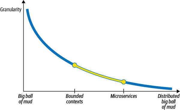
Figure 14-10. Granularity and modularity
Next, let’s examine the other extreme: whether aggregates can help find the microservices’ boundaries.
Aggregates
As bounded contexts, aggregates’ boundaries are also often considered to drive the boundaries of microservices. An aggregate is an indivisible business functionality unit that encapsulates the complexities of its internal business rules, invariants, and logic. That said, as you learned earlier in this chapter, microservices are not about individual services. An individual service has to be considered in the context of its interactions with other components of the system:
Does the aggregate in question communicate with other aggregates in its subdomain?
-
Does it share value objects with other aggregates?
-
How likely will the aggregate’s business logic changes affect other components of the subdomain and vice versa?
The stronger the aggregate’s relationship is with the other business entities of its subdomain, the shallower it will be as an individual service.
There will be cases in which having an aggregate as a service will produce a modular design. However, much more often such fine-grained services will increase the overarching system’s global complexity.
Subdomains
A more balanced heuristic for designing microservices is to
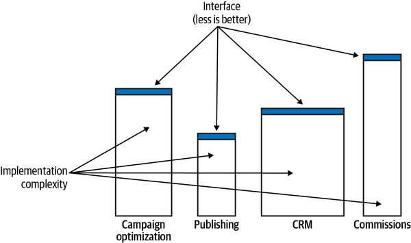
Figure 14-11. Subdomains
The subdomains’ granularity and the focus on the functionality—the “what” rather than the “how”—makes
Compressing Microservices’ Public Interfaces
In addition to finding service boundaries, domain-driven design can help make services deeper. This section demonstrates how the open-host service and anticorruption layer patterns can simplify the microservices’ public interfaces.
Open-Host Service
The open-host service decouples the bounded context’s model
Introducing the integration-oriented model, the published language, reduces the system’s global complexity. First, it allows us to evolve the service’s implementation without impacting its consumers: the new implementation model can be translated to the existing published language. Second, the published language exposes a more restrained model. It is designed around integration needs. It encapsulates the complexity of the implementation that is not relevant to the service’s consumers. For example, it can expose less data and in a more convenient model for consumers.
Having a simpler public interface (function) over the same implementation (logic) makes the service “deeper” and contributes to a more effective microservice design.
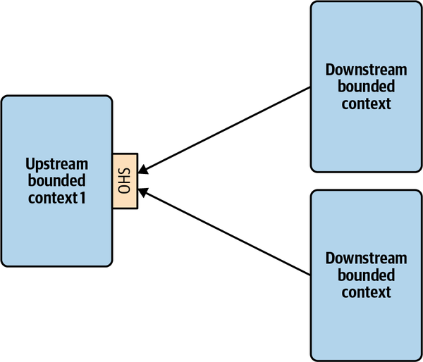
Figure 14-12. Integrating services through a published language
Anticorruption Layer
The anticorruption layer (ACL) pattern works the other way around.
The ACL service in Figure 14-13 reduces both the local complexity of the consuming bounded context and the system’s global complexity. The consuming bounded context’s business complexity is separated from the integration complexity. The latter is offloaded to the ACL service. Because the consuming bounded context is working with a more convenient, integration-oriented model, its public interface is compressed—it doesn’t reflect the integration complexity exposed by the producing service.
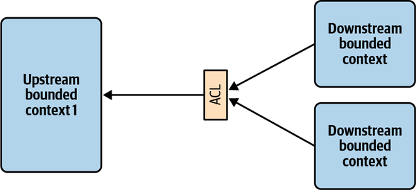
Figure 14-13. Anticorruption layer as a stand-alone service
Conclusion
Historically, the microservice-based architectural style is deeply interconnected with domain-driven design, so much so that the terms microservice and bounded context are often used interchangeably. In this chapter, we analyzed the connection between the two and saw that they are not the same thing.
All microservices are bounded contexts, but not all bounded contexts are necessarily microservices. In its essence, a microservice defines the smallest valid boundary of a service, while a bounded context protects the consistency of the encompassed model and represents the widest valid boundaries. Defining boundaries to be wider than their bounded contexts will result in a big ball of mud, while boundaries that are smaller than microservices will lead to a distributed big ball of mud.
Nevertheless, the connection between microservices and domain-driven design is tight. We saw how domain-driven design tools can be used to design effective microservice boundaries.
In Chapter 15, we will continue discussing high-level system architecture but from a different perspective: asynchronous integration through event-driven architecture. You will learn how to leverage the different kinds of event messages to further optimize microservices’ boundaries.
Exercises
-
What is the relationship between bounded contexts and microservices?
-
All microservices are bounded contexts.
-
All bounded contexts are microservices.
-
Microservices and bounded contexts are different terms for the same concept.
-
Microservices and bounded contexts are completely different concepts and cannot be compared.
-
-
What part of a microservice should be “micro”?
-
The number of pizzas required to feed the team implementing the microservices. The metric has to take into account the team members’ different dietary preferences and average daily calorie intakes.
-
The number of lines of code it takes to implement the service’s functionality. Since the metric is agnostic of the lines’ widths, it’s preferable to implement microservices on ultrawide monitors.
-
The most important aspect of designing microservices-based systems is to get microservices-friendly middleware and other infrastructural components, preferably from microservices-certified vendors.
-
The knowledge of the business domain and its intricacies exposed across the service’s boundary and reflected by its public interface.
-
-
What are the safe component boundaries?
-
Boundaries wider than bounded contexts.
-
Boundaries narrower than microservices.
-
Boundaries between bounded contexts (widest) and microservices (narrowest).
-
All boundaries are safe.
-
-
Is it a good design decision to align microservices with the boundaries of aggregates?
-
Yes, aggregates always make for proper microservices.
-
No, aggregates should never be exposed as individual microservices.
-
It’s impossible to make a microservice out of a single aggregate.
-
The decision depends on the business domain.
-
1 Reference model for service-oriented architecture v1.0. (n.d.). Retrieved June 14, 2021, from OASIS.
Chapter 15. Event-Driven Architecture
As microservices, event-driven architecture (EDA) is ubiquitous
Event-driven architecture is often linked to domain-driven design. After all, EDA is based on events, and events are prominent in DDD—we have domain events, and when needed, we even use events as the system’s source of truth. It may be tempting to leverage DDD’s events as the basis for using event-driven architecture. But is this a good idea?
Events are not a kind of secret sauce that you can just pour over a legacy system and turn it into a loosely coupled distributed system. Quite the opposite: careless application of EDA can turn a modular monolith into a distributed big ball of mud.
In this chapter, we will explore the interplay between EDA and DDD. You will learn the essential building blocks of event-driven architecture, common causes for failed EDA projects, and how you can leverage DDD’s tools to design effective, asynchronously integrated systems.
Event-Driven Architecture
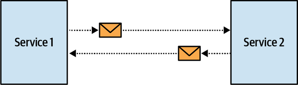
Figure 15-1. Asynchronous communication
It’s important to highlight the difference between
Although both event-driven architecture and event sourcing are based on events, the two patterns are conceptually different.
As you will see later in this chapter, there are three types of events, and some are more suited for integration than others.
Events
Events, Commands, and Messages
- Event
- A message describing a change that has already happened
- Command
- A message describing an operation that has to be carried out
An event is something that has already happened, whereas a command is an instruction to do something. Both events and commands can be communicated asynchronously as messages. However, a command can be rejected: the command’s target can refuse to execute the command, for example, if the command is invalid or if it contradicts the system’s business rules. A recipient of an event, on the other hand, cannot cancel the event. The event describes something that has already happened. The only thing that can be done to overturn an event is to issue a compensating action—a command, as it’s carried out in the saga pattern.
Structure
{"type":"delivery-confirmed","event-id":"14101928-4d79-4da6-9486-dbc4837bc612","correlation-id":"08011958-6066-4815-8dbe-dee6d9e5ebac","delivery-id":"05011927-a328-4860-a106-737b2929db4e","timestamp":1615718833,"payload":{"confirmed-by":"17bc9223-bdd6-4382-954d-f1410fd286bd","delivery-time":1615701406}}
An event’s payload not only describes the information conveyed by the event, but also defines the event’s type. Let’s discuss the three types of events in detail and how they differ from one another.
Types of Events
Event notification
An event notification is a message regarding a change in the business domain
The event notification should not be verbose: the goal is to notify the interested parties about the event, but the notification shouldn’t carry all the information needed for the subscribers to react to the event. For example:
{"type":"paycheck-generated","event-id":"537ec7c2-d1a1-2005-8654-96aee1116b72","delivery-id":"05011927-a328-4860-a106-737b2929db4e","timestamp":1615726445,"payload":{"employee-id":"456123","link":"/paychecks/456123/2021/01"}}
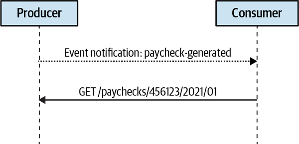
Figure 15-2. Event notification flow
In a sense, integration through event notification messages is similar to the Wireless Emergency Alert (WEA) system in the United States and EU-Alert in Europe (see Figure 15-3). The systems use cell towers to broadcast short messages, notifying citizens about public health concerns, safety threats, and other emergencies. The systems are limited to sending messages with a maximum length of 360 characters. This short message is enough to notify you about the emergency, but you have to proactively use other information sources to get more details.

Figure 15-3. Emergency alert system
Succinct event notifications can be preferable in multiple scenarios. Let’s take a closer look at two: security and concurrency.
Security
Enforcing the recipient to explicitly query for the detailed information
Concurrency
Furthermore, in the case of concurrent consumers, where only one subscriber should process an event, the querying process can be integrated with pessimistic locking. This ensures the producer’s side that no other consumer will be able to process the message.
Event-carried state transfer
ECST messages can come in two forms. The first is a complete snapshot of the modified entity’s state:
{"type":"customer-updated","event-id":"6b7ce6c6-8587-4e4f-924a-cec028000ce6","customer-id":"01b18d56-b79a-4873-ac99-3d9f767dbe61","timestamp":1615728520,"payload":{"first-name":"Carolyn","last-name":"Hayes","phone":"555-1022","status":"follow-up-set","follow-up-date":"2021/05/08","birthday":"1982/04/05","version":7}}
The ECST message in the preceding example includes a complete snapshot of a customer’s updated state. When operating large data structures, it may be reasonable to include in the ECST message only the fields that were actually modified:
{"type":"customer-updated","event-id":"6b7ce6c6-8587-4e4f-924a-cec028000ce6","customer-id":"01b18d56-b79a-4873-ac99-3d9f767dbe61","timestamp":1615728520,"payload":{"status":"follow-up-set","follow-up-date":"2021/05/10","version":8}}
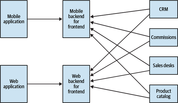
Figure 15-4. Backend for frontend
Domain event
The third type of event message is the domain event that we described
Domain events versus event notification
Both domain events and event notifications describe
First, domain events include all the information describing the event. The consumer does not need to take any further action to get the complete picture.
Second, the modeling intent is different. Event notifications are designed with the intent to alleviate integration with other components. Domain events, on the other hand, are intended to model and describe the business domain. Domain events can be useful even if no external consumer is interested in them. That’s especially true in event-sourced systems, where domain events are used to model all possible state transitions. Having external consumers interested in all the available domain events would result in suboptimal design. We will discuss this in greater detail later in this chapter.
Domain events versus event-carried state transfer
An ECST message provides sufficient information to hold a local cache of the producer’s data. No single domain event is supposed to expose such a rich model. Even the data included in a specific domain event is not sufficient for caching the aggregate’s state, as other domain events that the consumer is not subscribed to may affect the same fields.
Furthermore, as in the case of notification events, the modeling intent is different for the two types of messages. The data included in domain events is not intended to describe the aggregate’s state. Instead, it describes a business event that happened during its lifecycle.
Event types: Example
eventNotification={"type":"marriage-recorded","person-id":"01b9a761","payload":{"person-id":"126a7b61","details":"/01b9a761/marriage-data"}};ecst={"type":"personal-details-changed","person-id":"01b9a761","payload":{"new-last-name":"Williams"}};domainEvent={"type":"married","person-id":"01b9a761","payload":{"person-id":"126a7b61","assumed-partner-last-name":true}};
marriage-recorded is an event notification message. It contains no information except the fact that the person with the specified ID got married. It contains minimal information about the event, and the consumers interested in more details will have to follow the link in the details field.
personal-details-changed is an event-carried state transfer message. It describes the changes in the person’s personal details, namely that their last name has been changed. The message doesn’t explain the reason why it has changed. Did the person get married or divorced?
married is a domain event. It is modeled as close as possible to the nature of the event in the business domain. It includes the person’s ID and a flag indicating whether the person assumed their partner’s name.Designing Event-Driven Integration
In this section, you will learn heuristics for applying different event types. But first, let’s see how to use events to design a strongly coupled, distributed big ball of mud.
Distributed Big Ball of Mud
The CRM bounded context is implemented as an event-sourced domain model. When the CRM system had to be integrated with the Marketing bounded context, the teams decided to leverage the event-sourced data model’s flexibility and let the consumer—in this case, Marketing—subscribe to the CRM’s domain events and use them to project the model that fits their needs.
When the AdsOptimization bounded context was introduced, it also had to process the information produced by the CRM bounded context. Again, the teams decided to let AdsOptimization subscribe to all domain events produced in the CRM and project the model that fits AdsOptimization’s needs.
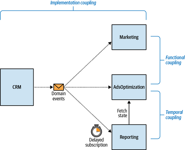
Figure 15-5. Strongly coupled distributed system
Interestingly, both the Marketing and AdsOptimization bounded contexts had to present the customers’ information in the same format, and hence ended up projecting the same model out of the CRM’s domain events: a flattened snapshot of each customer’s state.
The Reporting bounded context subscribed only to a subset of domain events published by the CRM and used as event notification messages to fetch the calculations performed in the AdsOptimization context. However, since both AdsOptimization bounded contexts use the same events to trigger their calculations, to ensure that the Reporting model is updated the AdsOptimization context introduced a delay. It processed messages five minutes after receiving them.
This design is terrible. Let’s analyze the types of coupling in this system.
Temporal Coupling
To enforce the required execution order, the engineers introduced the processing delay in the Reporting system. This delay of five minutes lets the AdsOptimization component finish the required calculations. Obviously, this doesn’t prevent incorrect order of execution:
-
AdsOptimization may be overloaded and unable to finish the processing in five minutes.
-
A network issue may delay the delivery of incoming messages to the AdsOptimization service.
-
The AdsOptimization component can experience an outage and stop processing incoming messages.
Functional Coupling
That’s an example of functional coupling: multiple components implementing the same business functionality, and if it changes, both components have to change simultaneously.
Implementation Coupling
Refactoring the Event-Driven Integration
Exposing all the domain events constituting the CRM’s data model couples the subscribers to the producer’s implementation details. The implementation coupling can be addressed by exposing either a much more restrained set of events or a different type of events.
The Marketing and AdsOptimization subscribers are functionally coupled to each other by implementing the same business functionality.
Both implementation and functional coupling can be tackled by encapsulating the projection logic in the producer: the CRM bounded contexts. Instead of exposing its implementation details, the CRM can follow the consumer-driven contract pattern: project the model needed by the consumers and make it a part of the bounded context’s published language—an integration-specific model, decoupled from the internal implementation model. As a result, the consumers get all the data they need and are not aware of the CRM’s implementation model.
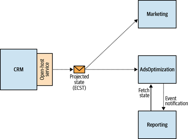
Figure 15-6. Refactored system
Event-Driven Design Heuristics
Matching types of events to the tasks at hand makes the resultant design orders of magnitude less coupled, more flexible, and fault tolerant. Let’s formulate the design heuristics behind the applied changes.
Assume the worst
As Andrew Grove put it, only the paranoid
-
The network is going to be slow.
-
Servers will fail at the most inconvenient moment.
-
Events will arrive out of order.
-
Events will be duplicated.
Most importantly, these events will occur most frequently on weekends and public holidays.
The word driven in event-driven architecture means your whole system depends on successful delivery of the messages. Hence, avoid the “things will be okay” mindset like the plague. Ensure that the events are always delivered consistently, no matter what:
-
Use the outbox pattern to publish messages reliably.
-
When publishing messages, ensure that the subscribers will be able to deduplicate the messages and identify and reorder out-of-order messages.
-
Leverage the saga and process manager patterns when orchestrating cross-bounded context processes that require issuing compensating actions.
Use public and private events
Be wary of exposing implementation details when publishing
When designing bounded contexts’ public interfaces, leverage the different types of events. Event-carried state transfer messages compress the implementation model into a more compact model that communicates only the information the consumers need.
Event notification messages can be used to further minimize the public interface.
Finally, sparingly use domain events for communication with external bounded contexts. Consider designing a set of dedicated public domain events.
Evaluate consistency requirements
When designing event-driven communication, evaluate the bounded contexts’ consistency requirements as an additional heuristic for choosing the event type:
-
If the components can settle for eventually consistent data, use the event-carried state transfer message.
-
If the consumer needs to read the last write in the producer’s state, issue an event notification message, with a subsequent query to fetch the producer’s up-to-date state.
Conclusion
This chapter presented event-driven architecture as an inherent aspect of designing a bounded context’s public interface. You learned the three types of events that can be used for cross-bounded context communication:
- Event notification
- A notification that something important has happened, but requiring the consumer to query the producer for additional information explicitly.
- Event-carried state transfer
- A message-based data replication mechanism. Each event contains a snapshot of a state that can be used to maintain a local cache of the producer’s data.
- Domain event
- A message describing an event in the producer’s business domain.
Using inappropriate types of events will derail an EDA-based system, inadvertently turning it into a big ball of mud. To choose the correct type of events for integration, evaluate the bounded contexts’ consistency requirements and be wary of exposing implementation details. Design an explicit set of public and private events. Finally, ensure that the system delivers the messages, even in the face of technical issues and outages.
Exercises
-
Which of the following statements is/are correct?
-
Event-driven architecture defines the events intended to travel across components’ boundaries.
-
Event sourcing defines the events that are intended to stay within the bounded context’s boundary.
-
Event-driven architecture and event sourcing are different terms for the same pattern.
-
A and B are correct.
-
-
What type of event is best suited for communicating changes in state?
-
Event notification.
-
Event-carried state transfer.
-
Domain event.
-
All event types are equally good for communicating changes in state.
-
-
Which bounded context integration pattern calls for explicitly defining public events?
-
Open-host service
-
Anticorruption layer
-
Shared kernel
-
Conformist
-
-
The services S1 and S2 are integrated asynchronously. S1 has to communicate data and S2 needs to be able to read the last written data in S1. Which type of event fits this integration scenario?
-
S2 should publish event-carried state transfer events.
-
S2 should publish public event notifications, which will signal S1 to issue a synchronous request to get the most up-to-date information.
-
S2 should publish domain events.
-
A and B.
-
1 Hohpe, G., & Woolf, B. (2003). Enterprise Integration Patterns: Designing, Building, and Deploying Messaging Solutions. Boston: Addison-Wesley.
2 Fowler, M. (n.d.). What do you mean by “Event-Driven”? Retrieved August 12, 2021, from Martin Fowler (blog).
3 Grove, A. S. (1998). Only the Paranoid Survive. London: HarperCollins Business.
Chapter 16. Data Mesh
So far in this book, we have discussed models used to build operational systems.
In this chapter, you will learn about the analytical data management architecture called data mesh. You will see how the data mesh–based architecture works and how it differs from the more traditional OLAP data management approaches. Ultimately, you will see how domain-driven design and data mesh accommodate each other. But first, let’s see what these analytical data models are and why we can’t just reuse the operational models for analytical use cases.
Analytical Data Model Versus Transactional Data Model
The analytical models (OLAP) and operational models (OLTP) serve different types of consumers, enable the implementation of different kinds of use cases, and are therefore designed following other design principles.
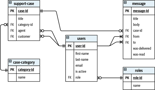
Figure 16-1. A relational database schema describing the relationships between entities in an operational model
Analytical models are designed to provide different insights into the operational systems. Instead of implementing real-time transactions, an analytical model aims to provide insights into the performance of business activities and, more importantly, how the business can optimize its operations to achieve greater value.
From a data structure perspective, OLAP models ignore the individual business entities and instead focus on business activities by modeling fact tables and dimension tables. We’ll take a closer look at each of these tables next.
Fact Table
Facts represent business activities that have already happened.
Fact_CustomerOnboardings would contain a record for each new onboarded customer and Fact_Sales a record for each committed sale. 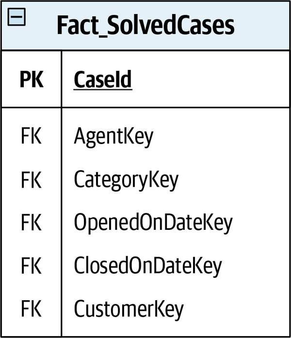
Figure 16-2. A fact table containing records for cases solved by a company’s support desk
Also, similar to domain events, fact records are never deleted or modified: analytical data is append-only data: the only way to express that current data is outdated is to append a new record with the current state. Consider the fact table Fact_CaseStatus in Figure 16-3. It contains the measurements of the statuses of support requests through time. There is no explicit verb in the fact name, but the business process captured by the fact is the process of taking care of support cases.
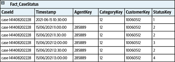
Figure 16-3. A fact table describing state changes during the lifecycle of a support case
Another significant difference between the OLAP and OLTP models is the granularity of the data. Operational systems require the most precise data to handle business transactions. For analytical models, aggregated data is more efficient in many use cases. For example, in the Fact_CaseStatus table shown in Figure 16-3, you can see that the snapshots are taken every 30 minutes. The data analysts working with the model decide what level of granularity will best suit their needs. Creating a fact record for each change of the measurement—for example, each change of a case’s data—would be wasteful in some cases and even technically impossible in others.
Dimension Table
SolvedCases fact with its dimensions. 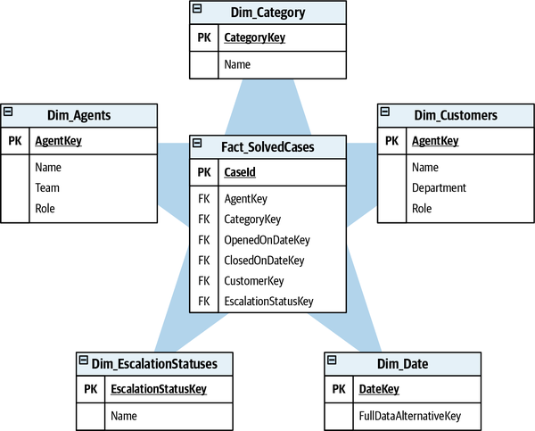
Figure 16-4. The SolvedCases fact surrounded by its dimensions
The reason for the high normalization of the dimensions is the analytical system’s need to support flexible querying. That’s another difference between operational and analytical models. It’s possible to predict how an operational model will be queried to support the business requirements. The querying patterns of the analytical models are not predictable. The data analysts need flexible ways of looking at the data, and it’s hard to predict what queries will be executed in the future. As a result, the normalization supports dynamic querying and filtering, and grouping the facts data across the different dimensions.
Analytical Models
The table structure depicted in Figure 16-5 is called
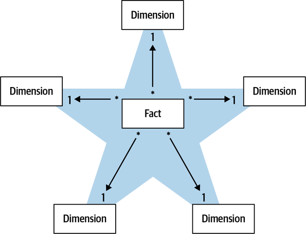
Figure 16-5. The many-to-one relationship between facts and their dimensions
As a result of the additional normalization, the snowflake schema will use less space to store the dimension data and is easier to maintain. However, querying the facts’ data will require joining more tables, and therefore, more computational resources are needed.
Both the star and snowflake schemas allow data analysts to analyze business performance, gaining insights into what can be optimized and built into business intelligence (BI) reports.
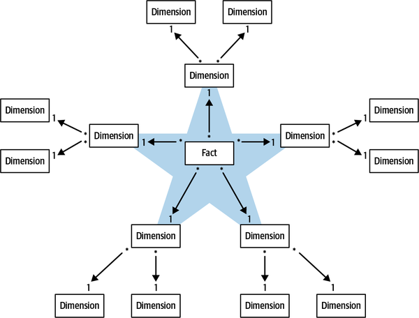
Figure 16-6. Multilevel dimensions in the snowflake schema
Analytical Data Management Platforms
Let’s shift the discussion from analytical modeling to data management
Data Warehouse
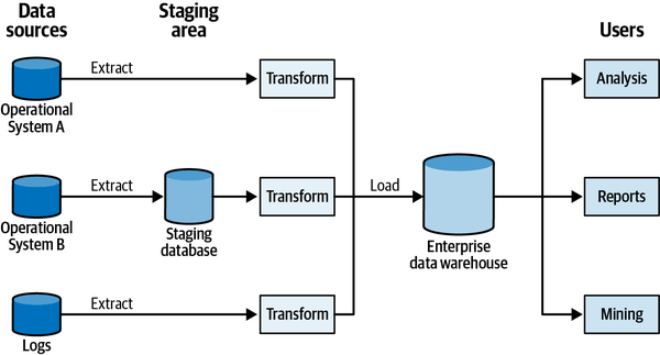
Figure 16-7. A typical enterprise data warehouse architecture
The careful reader will notice that the data warehouse architecture shares some of the challenges discussed in Chapters 2 and 3.
First, at the heart of the data warehouse architecture is the goal of building an enterprise-wide model. The model should describe the data produced by all of the enterprise’s systems and address all of the different use cases for analytical data. The analytical model enables, for example, optimizing the business, reducing operational costs, making intelligent business decisions, reporting, and even training ML models. As you learned in Chapter 3, such an approach is impractical for anything by the smallest organizations. Designing a model for the task at hand, such as building reports or training ML models, is a much more effective and scalable approach.
The challenge of building an all-encompassing model can be partly addressed by the use of data marts. A data mart is a database that holds data relevant for well-defined analytical needs, such as analysis of a single business department. In the data mart model shown in Figure 16-8, one mart is populated directly by an ETL process from an operational system, while another mart extracts its data from the data warehouse.
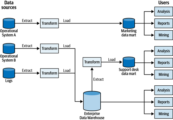
Figure 16-8. The enterprise data warehouse architecture augmented with data marts
When the data is ingested into a data mart from the enterprise data warehouse, the enterprise-wide model still needs to be defined in the data warehouse. Alternatively, data marts can implement dedicated ETL processes to ingest data directly from the operational systems. In this case, the resultant model makes it challenging to query data across different marts—for example, across different departments—as it requires a cross-database query and significantly impacts performance.
Another challenging aspect of the data warehouse architecture
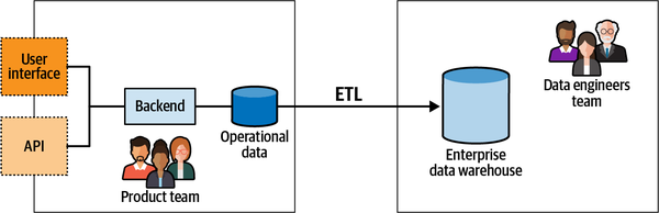
Figure 16-9. Data warehouse populated by fetching data directly from operational databases, ignoring the integration-oriented public interfaces
The data lake architecture addresses some of the shortcomings of the data warehouse architecture.
Data Lake
A data lake–based system ingests the operational systems’ data. However, instead of being transformed right away into an analytical model, the data is persisted in its raw form, that is, in the original operational model.
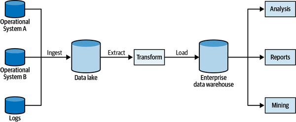
Figure 16-10. Data lake architecture
Since the operational systems’ data is persisted in its original, raw form and is transformed only afterward, the data lake allows working with multiple, task-oriented analytical models. One model can be used for reporting, another for training ML models, and so on. Furthermore, new models can be added in the future and initialized with the existing raw data.
That said, the delayed generation of analytical models increases the complexity of the overall system. It’s not uncommon for data engineers to implement and support multiple versions of the same ETL script to accommodate different versions of the operational model, as shown in Figure 16-11.
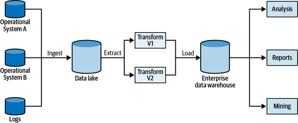
Figure 16-11. Multiple versions of the same ETL script accommodating different versions of the operational model
Furthermore, since data lakes are schema-less—there is no schema imposed on the incoming data—and there is no control over the quality of the incoming data, the data lake’s data becomes chaotic at certain levels of scale. Data lakes make it easy to ingest data but much more challenging to make use of it. Or, as is often said, a data lake becomes a data swamp. The data scientist’s job becomes orders of magnitude more complex to make sense of the chaos and to extract useful analytical data.
Challenges of Data Warehouse and Data Lake Architectures
From a modeling perspective, both architectures trespass the boundaries of the operational systems and create dependencies on their implementation details. The resultant coupling to the implementation models creates friction between the operational and analytical systems teams, often to the point of preventing changes to the operational models for the sake of not breaking the analysis system’s ETL jobs.
To make matters worse, since the data analysts and data engineers belong to a separate organizational unit, they often lack the deep knowledge of the business domain possessed by the operational systems’ development teams. Instead of the knowledge of the business domain, they are specialized mainly in big data tooling.
Last but not least, the coupling to the implementation models is especially acute in domain-driven design–based projects, in which the emphasis is on continuously evolving and improving the business domain’s models. As a result, a change in the operational model can have unforeseen consequences in the analytical model. Such changes are frequent in DDD projects and often result in friction between R&D and data teams.
These limitations of data warehouses and data lakes inspired a new analytical data management architecture: data mesh.
Data Mesh
The data mesh architecture is based on four core principles: decompose data around domains, data as a product, enable autonomy, and build an ecosystem. Let’s discuss each principle in detail.
Decompose Data Around Domains
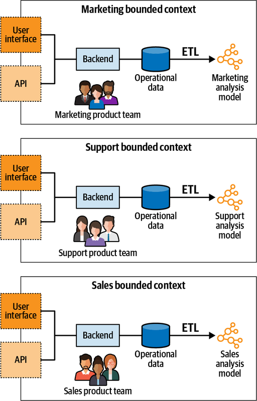
Figure 16-12. Aligning the ownership boundaries of the analytical models with the bounded contexts’ boundaries
Each bounded context now owns its operational (OLTP) and analytical (OLAP) models. Consequently, the same team owns the operational model, now in charge of transforming it into the analytical model.
Data as a Product
The classic data management architectures make it difficult to discover,
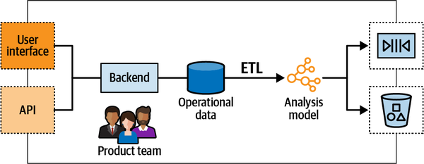
Figure 16-13. Polyglot data endpoints exposing the analytical data to the consumers
Analytical data should be treated the same as any public API:
-
It should be easy to discover the necessary endpoints: the data output ports.
-
The analytical endpoints should have a well-defined schema describing the served data and its format.
-
The analytical data should be trustworthy, and as with any API, it should have defined and monitored service-level agreements (SLAs).
-
The analytical model should be versioned as a regular API and correspondingly manage integration-breaking changes in the model.
Furthermore, since the analytical data is treated as a product, it has to address the needs of its consumers. The bounded context’s team is in charge of ensuring that the resultant model addresses the needs of its consumers. Contrary to the data warehouse and data lake architectures, with data mesh, accountability for data quality is a top-level concern.
The goal of the distributed data management architecture is to allow the fine-grained analytical models to be combined to address the organization’s data analysis needs. For example, if a BI report should reflect data from multiple bounded contexts, it should be able to easily fetch their analytical data if needed, apply local transformations, and produce the report.
Finally, different consumers may require the analytical data in different forms. Some may prefer to execute SQL queries, others to fetch analytical data from an object storage service, and so on. As a result, the data products have to be polyglot, serving the data in formats that suit different consumers’ needs.
To implement the data as a product principle, product teams require adding data-oriented specialists. That’s the missing piece in the cross-functional teams puzzle, which traditionally includes only specialists related to the operational systems.
Enable Autonomy
The product teams should be able to both create their own data products
It would be wasteful, inefficient, and hard to integrate if each team builds their own solution for serving analytical data. To prevent this from happening, a platform is needed to abstract the complexity of building, executing, and maintaining interoperable data products. Designing and building such a platform is a considerable undertaking and requires a dedicated data infrastructure platform team.
The data infrastructure platform team should be in charge of defining the data product blueprints, unified access patterns, access control, and polyglot storage that can be leveraged by product teams, as well as monitoring the platform and ensuring that the SLAs and objectives are met.
Build an Ecosystem
The governance group is in charge of defining the rules to ensure a healthy and interoperable ecosystem. The rules have to be applied to all data products and their interfaces, and it’s the group’s responsibility to ensure adherence to the rules throughout the enterprise.
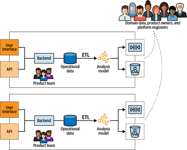
Figure 16-14. The governance group, which ensures that the distributed data analytics ecosystem is interoperable, healthy, and serves the organization’s needs
Combining Data Mesh and Domain-Driven Design
These are the four principles that the data mesh architecture is based on.
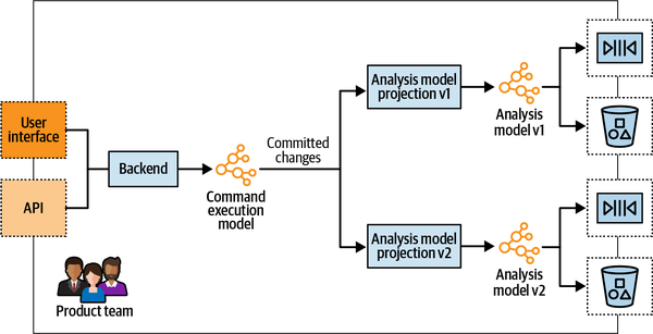
Figure 16-15. Leveraging the CQRS pattern to simultaneously serve the analytical data in two different schema versions
Finally, since the data mesh architecture combines the different bounded contexts’ models to implement analytical use cases, the bounded context integration patterns for operational models apply for analytical models as well. Two product teams can evolve their analytical models in partnership. Another can implement an anticorruption layer to protect itself from an ineffective analytical model. Or, on the other hand, the teams can go their separate ways and produce duplicate implementations of analytical models.
Conclusion
In this chapter, you learned the different aspects of designing software systems, in particular, defining and managing analytical data. We discussed the predominant models for analytical data, including the star and snowflake schemas, and how the data is traditionally managed in data warehouses and data lakes.
The data mesh architecture aims to address the challenges of the traditional data management architectures. At its core, it applies the same principles as domain-driven design but to analytical data: decomposing the analytical model into manageable units and ensuring that the analytical data can be reliably accessed and used through its public interfaces. Ultimately, the CQRS and bounded context integration patterns can support implementing the data mesh architecture.
Exercises
-
Which of the following statements is/are correct regarding the differences between transactional (OLTP) and analytical (OLAP) models?
-
OLAP models should expose more flexible querying options than OLTP models.
-
OLAP models are expected to undergo more updates than OLTP models, and thus have to be optimized for writes.
-
OLTP data is optimized for real-time operations, whereas it’s acceptable to wait seconds or even minutes for an OLAP query’s response.
-
A and C are correct.
-
-
Which bounded context integration pattern is essential for implementation of the data mesh architecture?
-
Shared kernel
-
Open-host service
-
Anticorruption layer
-
Partnership
-
-
Which architectural pattern is essential for implementation of the data mesh architecture?
-
Layered architecture.
-
Ports & adapters.
-
CQRS.
-
Architectural patterns cannot support implementation of an OLAP model.
-
-
The definition of data mesh architecture calls for decomposing data around “domains.” What is DDD’s term for denoting the data mesh’s domains?
-
Bounded contexts.
-
Business domains.
-
Subdomains.
-
There is no synonym for a data mesh’s domains in DDD.
-
Closing Words
To complete our exploration of domain-driven design I want to get back to the quote we started with:
There is no sense in talking about the solution before we agree on the problem, and no sense talking about the implementation steps before we agree on the solution.
Efrat Goldratt-Ashlag
This quote neatly summarizes our DDD journey.
Problem
We used the ubiquitous language to gain a deep understanding of the business domain and its logic that we have to implement in software.
You learned to manage the complexity of the business problem by breaking it apart into bounded contexts. Each bounded context implements a single model of the business domain, aimed at solving a specific problem.
| Subdomain type | Competitive advantage | Complexity | Volatility | Implementation | Problem |
| Core | Yes | High | High | In-house | Interesting |
| Generic | No | High | Low | Buy/adopt | Solved |
| Supporting | No | Low | Low | In-house/outsource | Obvious |
Solution
You learned to leverage this knowledge to design solutions optimized for each type of subdomain. We discussed four business logic implementation patterns—transaction script, active record, domain model, and event sourced domain model—and the scenarios in which each pattern shines. You also saw three architectural patterns that provide the required scaffolding for the implementation of business logic: layered architecture, ports & adapters, and CQRS. Figure E-1 summarizes the heuristics for tactical decision-making using these patterns.

Figure E-1. Decision tree summarizing heuristics for tactical decision-making
Implementation
In Part III, we discussed how to turn theory into practice. You learned how to effectively build a ubiquitous language by facilitating an EventStorming session, how to keep the design in shape as the business domain evolves, and how to introduce and start using domain-driven design in brownfield projects.
In Part IV, we discussed the interplay between domain-driven design and other methodologies and patterns: microservices, event-driven architecture, and data mesh. We saw that not only can DDD be used in tandem with these techniques, but they in fact complement each other.
Further Reading
Advanced Domain-Driven Design
- Evans, E. (2003).Domain-Driven Design: Tackling Complexity in the Heart of Software. Boston: Addison-Wesley.
Eric Evans’s original book that introduced the domain-driven design methodology. Although it doesn’t reflect newer aspects of DDD such as domain events and event sourcing, it’s still essential reading for becoming a DDD black belt.
Martraire, C. (2019). Living Documentation: Continuous Knowledge Sharing by Design. Boston: Addison-Wesley.
In this book, Cyrille Martraire proposes a domain-driven design–based approach to knowledge sharing, documentation, and testing.
Vernon, V. (2013). Implementing Domain-Driven Design. Boston: Addison-Wesley.
Another timeless DDD classic. Vaughn Vernon provides in-depth discussion and detailed examples of domain-driven design thinking and the use of its strategic and tactical toolset. As a learning foundation, Vaughn uses a real-world example of failing initiatives with DDD and the teams’ rejuvenated journey afforded by applying essential course corrections.
Young, G. (2017). Versioning in an Event Sourced System. Leanpub.
In Chapter 7, we discussed that it can be challenging to evolve an event-sourced system. This book is dedicated to this topic.
Architectural and Integration Patterns
Dehghani, Z. (Expected to be published in 2022). Data Mesh: Delivering Data-Driven Value at Scale. Boston: O’Reilly.
Zhamak Dehghani is the author of the data mesh pattern that we discussed inChapter 16. In this book, Dehghani explains the principles behind the data management architecture, as well as how to implement the data mesh architecture in practice.Fowler, M. (2002). Patterns of Enterprise Application Architecture. Boston: Addison-Wesley.
The classic application architecture patterns book that I quoted multiple times in Chapter 5 and Chapter 6. This is the book in which the transaction script, active record, and domain model patterns were originally defined.
Hohpe, G., & Woolf, B. (2003). Enterprise Integration Patterns: Designing, Building, and Deploying Messaging Solutions. Boston: Addison-Wesley.
Many of the patterns discussed in Chapter 9 were originally introduced in this book. Read this book for more component integration patterns.
Richardson, C. (2019). Microservice Patterns: With Examples in Java. New York: Manning Publications.
In this book, Chris Richardson provides many detailed examples of patterns often used when architecting microservices-based solutions. Among the discussed patterns are saga, process manager, and outbox, which we discussed in Chapter 9.
Modernization of Legacy Systems
Kaiser, S. (Expected to be published in 2022). Adaptive Systems with Domain-Driven Design, Wardley Mapping, and Team Topologies. Boston: Addison-Wesley.
Susanne Kaiser shares her experience of modernizing legacy systems by leveraging domain-driven design, Wardley mapping, and team topologies.
- Tune, N. (Expected to be published in 2022).Architecture Modernization: Product, Domain, & Team Oriented. Leanpub.
In this book, Nick Tune discusses in depth how to leverage domain-driven design and other techniques to modernize brownfield projects’ architecture.
Vernon, V., & Jaskula, T. (2021). Implementing Strategic Monoliths and Microservices. Boston: Addison-Wesley.
A hands-on book in which the authors demonstrate ageless software engineering tools, including rapid discovery and learning, domain-driven approaches, and handling the intricacies of properly implementing monolith- and microservices-based solutions, all while focusing on the most important aspect: delivering innovative business strategy.
Vernon, V., & Jaskula, T. (2021). Strategic Monoliths and Microservices. Boston: Addison-Wesley.
In this book Vaughn and Tomasz promote software strategic thinking by exploring how to achieve all-important innovations using discovery-based learning along with a domain-driven approach, and how to select the most purposeful architecture and tools for the job: microservices, monoliths, or a blend, and how to make them work together.
EventStorming
Brandolini, A. (Not yet published). Introducing EventStorming. Leanpub.
Alberto Brandolini is the creator of the EventStorming workshop, and in this book, he explains in detail the process and rationale behind EventStorming.
- Rayner, P. (Not yet published).The EventStorming Handbook. Leanpub.
Paul Rayner explains how he uses EventStorming in practice, including numerous tips and tricks for facilitating a successful session.
Conclusion
That’s it! Thank you so much for reading this book. I hope you enjoyed it and that you will use what you’ve learned from it.
What I hope you take away from this book are the logic and the principles behind domain-driven design tools. Don’t follow domain-driven design blindly as a dogma, but rather understand the reasoning it is based on. This understanding will significantly increase your opportunities to apply DDD and gain value from it. Understanding the philosophy of domain-driven design is also the key to leveraging value by incorporating the methodology’s concepts individually, especially in brownfield projects.
Finally, always watch your ubiquitous language, and when in doubt, do EventStorming. Good luck!
Appendix A. Applying DDD: A Case Study
In this appendix, I will share how my domain-driven design journey started:
Before we begin, I need to stress that Marketnovus doesn’t exist anymore. As a result, this appendix is in no way promotional. Furthermore, since this is a defunct company, I’m free to speak honestly about our experiences.
Five Bounded Contexts
Before we delve into the bounded contexts and how they were designed, as well-behaved DDD practitioners we have to start by defining Marketnovus’s business domain.
Business Domain
Imagine you are producing a product or a service. Marketnovus allowed
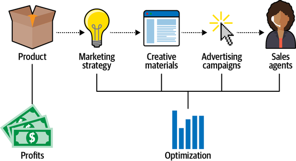
Figure A-1. Marketing process
Most importantly, this marketing process provided many opportunities for optimization, and that’s exactly what the analysis department was in charge of. They analyzed all the data to make sure Marketnovus and its clients were getting the biggest bang for their buck, whether by pinpointing the most successful campaigns, celebrating the most effective creatives, or ensuring that the sales agents were working on the most promising leads.
Since we were a self-funded company, we had to get rolling as fast as possible. As a result, right after the company was founded, the first version of our software system had to implement the first one-third of our value chain:
-
A system for managing contracts and integrations with external publishers
-
A catalog for our designers to manage creative materials
-
A campaign management solution to run advertising campaigns
I was overwhelmed and had to find a way to wrap my head around all the complexities of the business domain. Fortunately, not long before we started working, I read a book that promised just that.
Guess how the system was initially designed? It would definitely make a certain prominent individual1 from the DDD community very proud.
Bounded Context #1: Marketing
All of those so-called aggregates resided in a huge, lone, bounded context. Yes, a big, scary monolith, the kind everyone warns you about nowadays.
And of course, those were no aggregates. They didn’t provide any transactional boundaries, and they had almost no behavior in them. All the business logic was implemented in an enormous service layer.
From the business’s point of view, this project was considered a huge success! Despite the flawed architecture, we were able to deliver working software in a very aggressive time to market. How did we do it?
A kind of magic
The smooth communication with the domain experts allowed us to grasp the business domain in no time and implement its business logic. Yes, it was a pretty big monolith, but for two developers in a garage, it was just good enough. Again, we produced working software in a very aggressive time to market.
Our early understanding of domain-driven design
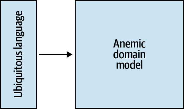
Figure A-2. Our early understanding of domain-driven design
Bounded Context #2: CRM
Soon after we deployed the campaign management solution,
The CRM had to aggregate all incoming leads, group them based on different parameters, and distribute them across multiple sales desks around the globe. It also had to integrate with our clients’ internal systems, both to notify the clients about changes in the leads’ lifecycles and to complement our leads with additional information. And, of course, the CRM had to provide as many optimization opportunities as possible. For example, we needed to be able to make sure the agents were working on the most promising leads, assign leads to agents based on their qualifications and past performance, and allow a very flexible solution for calculating agents’ commissions.
Since no off-the-shelf product fit our requirements, we decided to roll out our own CRM system.
More “aggregates”!
The initial implementation approach was to continue focusing on the tactical patterns. Again, we pronounced every noun as an aggregate and shoehorned them into the same monolith. This time, however, something felt wrong right from the start.
We noticed that, all too often, we were adding awkward prefixes to those “aggregates” names: for example, CRMLead and MarketingLead, MarketingCampaign and CRMCampaign. Interestingly, we never used those prefixes in our conversations with the domain experts. Somehow, they always understood the meaning from the context.
We took a step back and redesigned the CRM solution to reflect these revelations.
Solution design: Take two
We started by dividing our monolith into two distinct bounded contexts: marketing and CRM. Of course, we didn’t go all the way to microservices here; we just did the bare minimum to protect the ubiquitous language.
However, in the new bounded context, the CRM, we were not going to repeat the same mistakes we made in the marketing system. No more anemic domain models! Here we would implement a real domain model with real, by-the-book aggregates. In particular, we vowed that:
-
Each transaction would affect only one instance of an aggregate.
-
Instead of an ORM, each aggregate itself would define the transactional scope.
-
The service layer would go on a very strict diet, and all the business logic would be refactored into the corresponding aggregates.
We were so enthusiastic about doing things the right way. But, soon enough, it became apparent that modeling a proper domain model is hard!
Relative to the marketing system, everything took much more time! It was almost impossible to get the transactional boundaries right the first time. We had to evaluate at least a few models and test them, only to figure out later that the one we hadn’t thought about was the correct one. The price of doing things the “right” way was very high: lots of time.
Soon it became obvious to everyone that there was no chance in hell we would meet the deadlines! To help us out, management decided to offload implementation of some of the features to…the database administrators team.
Yes, to implement the business logic in stored procedures.
This one decision resulted in much damage down the line. Not because SQL is not the best language for describing business logic. No, the real issue was a bit more subtle and fundamental.
Tower of Babel 2.0
This situation produced an implicit bounded context whose boundary
The result was two teams working on the same business component and implementing closely related features, but with minimal interaction between them. Ubiquitous language? Give me a break! Literally, each team had its own vocabulary to describe the business domain and its rules.
The models were inconsistent. There was no shared understanding. Knowledge was duplicated, and the same rules were implemented twice. Rest assured, when the logic had to change, the implementations went out of sync immediately.
Needless to say, the project wasn’t delivered anywhere near on time, and it was full of bugs. Nasty production issues that had flown under the radar for years corrupted our most precious asset: our data.
The only way out of this mess was to completely rewrite the Lead aggregate, this time with proper boundaries, which we did a couple of years later. It wasn’t easy, but the mess was so bad there was no other way around it.
A broader understanding of domain-driven design
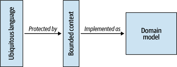
Figure A-3. Introduction of strategic design concepts into our understanding of domain-driven design
Of course, a crucial part of domain-driven design was missing here: subdomains, their types, and how they affect a system’s design.
Initially we wanted to do the best job possible, but we ended up wasting time and effort on building domain models for supporting subdomains. As Eric Evans put it, not all of a large system will be well designed. We learned that the hard way, and we wanted to use the acquired knowledge in our next project.
Bounded Context #3: Event Crunchers
Figure A-4. The event crunchers bounded context handling the incoming customer events
Since we didn’t make any money out of the way we move data around, and there weren’t any off-the-shelf solutions that could have been used, event crunchers resembled a supporting subdomain. We designed it as such.
Nothing fancy this time: just layered architecture and some simple transaction scripts. This solution worked great, but only for a while.
As our business evolved, we implemented more and more features in the event crunchers. It started with business intelligence (BI) people asking for some flags: a flag to mark a new contact, another one to mark various first-time events, some more flags to indicate some business invariants, and so on.
Eventually, those simple flags evolved into a real business logic, with complex rules and invariants. What started out as transaction scripts evolved into a full-fledged core business subdomain.
Unfortunately, nothing good happens when you implement complex business logic as transaction scripts. Since we didn’t adapt our design to cope with the complex business logic, we ended up with a very big ball of mud. Each modification to the codebase became more and more expensive, quality went downhill, and we were forced to rethink the event crunchers design. We did that a year later. By that time, the business logic had become so complex that it could only be tackled with event sourcing. We refactored the event crunchers’ logic into an event-sourced domain model, with other bounded contexts subscribing to its events.
Bounded Context #4: Bonuses
One day, the sales desk managers asked us to automate a simple
Again, it started out simple: once a month, just calculate a percentage of each agent’s sales and send the report to the managers. As before, we contemplated whether this was a core subdomain. The answer was no. We weren’t inventing anything new, weren’t making money out of this process, and if it was possible to buy an existing implementation, we definitely would. Not core, not generic, but another supporting subdomain.
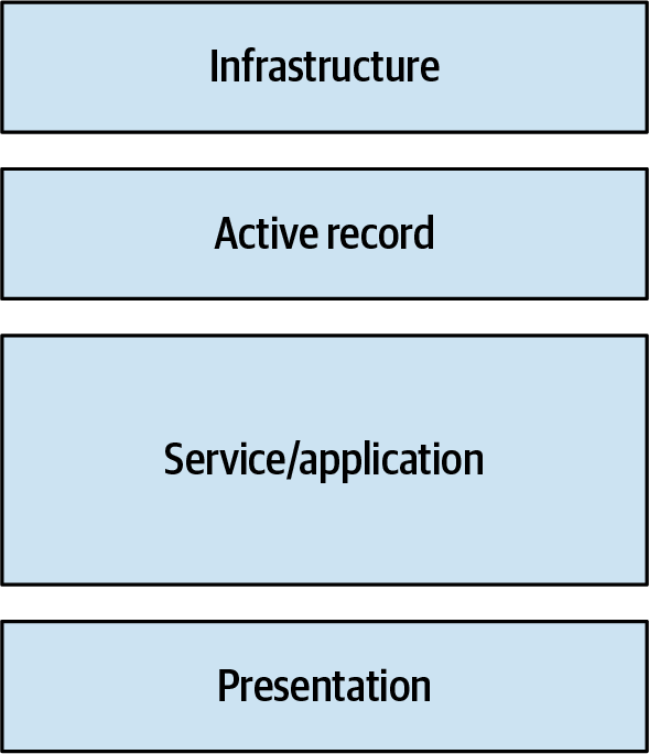
Figure A-5. The bonuses bounded context implemented using the active record and layered architecture patterns
Once the process became automated, boy, did everyone in the company become creative about it. Our analysts wanted to optimize the heck out of this process. They wanted to try out different percentages, tie percentages to sales amounts and prices, unlock additional commissions for achieving different goals, and on and on. Guess when the initial design broke down?
Again, the codebase started turning into an unmanageable ball of mud. Adding new features became more and more expensive, bugs started to appear—and when you’re dealing with money, even the smallest bug can have BIG consequences.
Design: Take two
As with the event crunchers project, at some point we couldn’t bear it anymore. We had to throw away the old code and rewrite the solution from the ground up, this time as an event-sourced domain model.
And just as in the event crunchers project, the business domain was initially categorized as a supporting one. As the system evolved, it gradually mutated into a core subdomain: we found ways to make money out of these processes. However, there is a striking difference between these two bounded contexts.
Ubiquitous language
For the bonuses project, we had a ubiquitous language. Even though
As the domain’s complexity grew, the language used by the domain experts got more and more complicated as well. At some point, it could no longer be modeled using active records! This realization allowed us to notice the need for a change in the design much earlier than we did in the event crunchers project. We saved a lot of time and effort by not trying to fit a square peg into a round hole, thanks to the ubiquitous language.
A classic understanding of domain-driven design
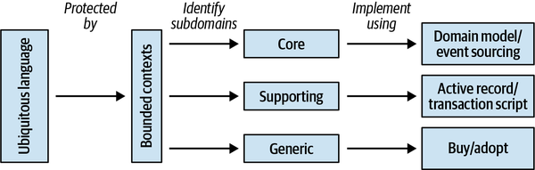
Figure A-6. A classic model of domain-driven design
However, things took quite an unexpected turn for our next project.
Bounded Context #5: The Marketing Hub
Our management was looking for a profitable new vertical. They
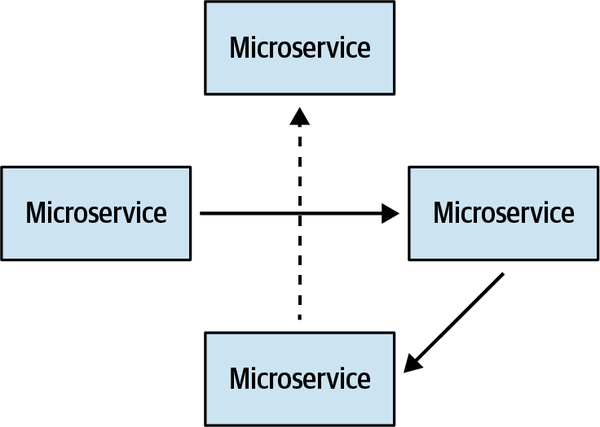
Figure A-7. A microservices-based implementation of the marketing hub bounded context
Small services, each having its own database, with both synchronous and asynchronous communication between them: on paper, it looked like a perfect solution design. In practice, not so much.
Micro what?
We näively approached microservices thinking that the smaller the service was, the better. So we drew service boundaries around the aggregates. In DDD lingo, each aggregate became a bounded context on its own.
Again, initially this design looked great. It allowed us to implement each service according to its specific needs. Only one would be using event sourcing, and the rest would be state-based aggregates. Moreover, all of them could be maintained and evolved independently.
However, as the system grew, those services became more and more chatty. Eventually, almost each service required data from all the other services to complete some of its operations. The result? What was intended to be a decoupled system ended up being a distributed monolith: an absolute nightmare to maintain.
Unfortunately, there was another, much more fundamental issue we had with this architecture. To implement the marketing hub, we used the most complex patterns for modeling the business domain: domain model and event-sourced domain model. We carefully crafted those services. But it all was in vain.
The real problem
Despite the fact that the business considered the marketing hub to be a core subdomain, it had no technical complexity. Behind that complex architecture stood a very simple business logic, one so simple that it could have been implemented using plain active records.
As it turned out, the businesspeople were looking to profit by leveraging our existing relationships with other companies, and not through the use of clever algorithms.
The technical complexity ended up being much higher than the business complexity.
Discussion
Those were the five bounded contexts I wanted to tell you about: marketing, CRM, event crunchers, bonuses, and marketing hub. Of course, such a wide business domain as Marketnovus entailed many more bounded contexts, but I wanted to share the bounded contexts we learned from the most.
Now that we’ve walked through the five bounded contexts, let’s look at this from a different perspective. How did application or misapplication of core elements of domain-driven design influence our outcomes? Let’s take a look.
Ubiquitous Language
Moreover, the presence of a ubiquitous language has been a major predictor of a project’s success for us:
-
When we started, our implementation of the marketing system was far from perfect. However, the robust ubiquitous language compensated for the architectural shortcomings and allowed us to deliver the project’s goals.
-
In the CRM context, we screwed it up. Unintentionally, we had two languages describing the same business domain. We strived to have a proper design, but because of the communication issues we ended up with a huge mess.
-
The event crunchers project started as a simple supporting subdomain, and we didn’t invest in the ubiquitous language. We regretted this decision big time when the complexity started growing. It would have taken us much less time if we initially started with a ubiquitous language.
-
In the bonuses project, the business logic became more complex by orders of magnitude, but the ubiquitous language allowed us to notice the need for a change in the implementation strategy much earlier.
Hence, ubiquitous language is not optional, regardless of whether you’re working on a core, supporting, or generic subdomain.
We learned the importance of investing in the ubiquitous language as early as possible. It requires immense effort and patience to “fix” a language if it has been spoken for a while in a company (as was the case with our CRM system). We were able to fix the implementation. It wasn’t easy, but eventually we did it. That’s not the case, however, for the language. For years, some people were still using the conflicting terms defined in the initial implementation.
Subdomains
Furthermore, as you learned in Chapter 11, it’s not enough to identify a subdomain’s type.
-
Both the event crunchers and bonuses started as supporting subdomains, but once we discovered ways to monetize these processes, they became our core subdomains.
-
In the marketing context, we implemented our own creative catalog. There was nothing really special or complex about it. However, a few years later, an open source project came out that offered even more features than we originally had. Once we replaced our implementation with this product, the supporting subdomain became a generic one.
-
In the CRM context, we had an algorithm that identified the most promising leads. We refined it over time and tried different implementations, but eventually it was replaced with a machine learning model running in a cloud vendor’s managed service. Technically, a core subdomain became generic.
-
As we’ve seen, our marketing hub system started as a core, but ended up being a supporting subdomain, since the competitive edge resided in a completely different dimension.
As you’ve learned throughout this book, the subdomain types affect a wide range of design decisions. Failing to properly identify a subdomain can be a costly mistake as, for example, in the case of the event crunchers and the marketing hub.
Mapping design decisions to subdomains
Here is a trick I came up with at Marketnovus to foolproof the identification of subdomains: reverse the relationship between subdomains and tactical design decisions. Choose the business logic implementation pattern. No speculation or gold plating; simply choose the pattern that fits the requirements at hand. Next, map the chosen pattern to a suitable subdomain type. Finally, verify the identified subdomain type with the business vision.
Reversing the relationship between subdomains and tactical design decisions creates an additional dialogue between you and the business. Sometimes businesspeople need us as much as we need them.
If they think something is a core business, but you can hack it in a day, then it is either a sign that you need to look for finer-grained subdomains or that questions should be raised about the viability of that business.
On the other hand, things get interesting if a subdomain is considered a supporting one by the business but can only be implemented using the advanced modeling techniques: domain model or event-sourced domain model.
First, the businesspeople may have gotten overly creative with their requirements and ended up with accidental business complexity. It happens. In such a case, the requirements can, and probably should, be simplified.
Second, it might be that the businesspeople don’t yet realize they employ this subdomain to gain an additional competitive edge. This happened in the case of the bonuses project. By uncovering this mismatch, you’re helping the business identify new profit sources faster.
Don’t ignore pain
Boundaries of Bounded Contexts
-
Linguistic boundaries: We split our initial monolith into marketing and CRM contexts to protect their ubiquitous languages.
-
Subdomain-based boundaries: Many of our subdomains were implemented in their own bounded contexts; for example, event crunchers and bonuses.
-
Entity-based boundaries: As we discussed earlier, this approach had limited success in the marketing hub project, but it worked in others.
-
Suicidal boundaries: As you may remember, in the initial implementation of the CRM we dissected an aggregate into two different bounded contexts. Never try this at home, okay?
This heuristic served us well. For example, in the cases of the marketing and CRM bounded contexts, each encompassed multiple subdomains. As time passed, we gradually decomposed the initially wide boundaries into microservices. As we defined in Chapter 14, throughout the evolution of the bounded contexts, we stayed in the range of the safe boundaries. We were able to avoid going past the safe boundaries by doing the refactoring only after gaining enough knowledge of the business domain.
Conclusion
In the stories of Marketnovus’s bounded contexts I showed how our understanding of domain-driven design evolved through time (refer to Figure A-6 for a refresher):
-
We always started by building a ubiquitous language with the domain experts to learn as much as possible about the business domain.
-
In the case of conflicting models, we decomposed the solution into bounded contexts, following the linguistic boundaries of the ubiquitous language.
-
We identified the subdomains’ boundaries and their types in each bounded context.
-
For each subdomain we chose an implementation strategy by using tactical design heuristics.
-
We verified the initial subdomain types with those resulting from the tactical design. In cases of mismatching types, we discussed them with the business. Sometimes this dialogue led to changes in the requirements, because we were able to provide a new perspective on the project to the product owners.
-
As more domain knowledge was acquired, and if it was needed, we decomposed the bounded contexts further into contexts with narrower boundaries.
If we compare this vision of domain-driven design with the one we started with, I’d say the main difference is that we went from “aggregates everywhere” to “ubiquitous language everywhere.”
In parting, since I’ve told you the story of how Marketnovus started, I want to share how it ended.
The company became profitable very quickly, and eventually it was acquired by its biggest client. Of course, I cannot attribute its success solely to domain-driven design. However, during all those years, we were constantly in “start-up mode.”
What we term “start-up mode” in Israel is called “chaos” in the rest of the world: constantly changing business requirements and priorities, aggressive time frames, and a tiny R&D team. DDD allowed us to tackle all of these complexities and keep delivering working software. Hence, when I look back, the bet we placed on domain-driven design paid off in full.
1 @DDDBorat is a parody Twitter account known for sharing bad advice on domain-driven design.
Appendix B. Answers to Exercise Questions
Chapter 1
-
D: B and C. Only core subdomains provide competitive advantages that differentiate the company from other players in its industry.
-
B: Generic. Generic subdomains are complex but do not entail any competitive advantage. Hence, it’s preferable to use an existing, battle-proven solution.
-
A: Core. Core subdomains are expected to be the most volatile since these are areas in which the company aims to provide new solutions and it often requires quite a few interactions to find the most optimized solution.
-
WolfDesk’s business domain is Help Desk management systems.
-
We can identify the following core subdomains that allow WolfDesk to differentiate itself from its competitors and support its business model:
-
Ticket lifecycle management algorithm that is intended to close tickets and thus encourage users to open new ones
-
Fraud detection system to prevent abuse of its business model
-
Support autopilot that both eases the tenants’ support agents’ work and further reduces the tickets’ lifespan
-
-
The following supporting subdomains can be identified in the description of the company:
-
Management of a tenant’s ticket categories
-
Management of a tenant’s products, regarding which the customers can open support tickets
-
Entry of a tenant’s support agents’ work schedules
-
-
The following generic subdomains can be identified in the description of the company:
-
“Industry standard” ways of authenticating and authorizing users
-
Using external providers for authentication and authorization (SSO)
-
The serverless compute infrastructure the company leverages to ensure elastic scalability and minimize the compute costs of onboarding new tenants
-
Chapter 2
-
D: All of the project’s stakeholders should contribute their knowledge and understanding of the business domain.
-
D: A ubiquitous language should be used in all project-related communication. The software’s source code should also “speak” its ubiquitous language.
-
WolfDesk’s customers are tenants. To start using the system, tenants go through a quick onboarding process. The company’s charging model is based on the number of tickets that were opened during a charging period. The ticket lifecycle management algorithm ensures that inactive tickets are automatically closed. WolfDesk’s fraud detection algorithm prevents tenants from abusing its business model. The support autopilot functionality tries to find solutions for new tickets automatically. A ticket belongs to a support category and is associated with a product for which the tenant provides support. A support agent can only process tickets during their work time, which is defined by their shift schedules.
Chapter 3
-
B: Bounded contexts are designed, while subdomains are discovered.
-
D: All of the above. A bounded context is a boundary of a model, and a model is only applicable in its bounded context. Bounded contexts are implemented in independent projects/solutions, thus allowing each bounded context to have its own development lifecycle. Finally, a bounded context should be implemented by a single development team, and therefore, it is also an ownership boundary.
-
D: It depends. There is no perfect size of a bounded context for all projects and cases. Different factors, such as models, organizational constraints, and nonfunctional requirements, affect the optimum scope of a bounded context.
-
D: B and C are correct. A bounded context should be owned by one team only. At the same time, the same team can own multiple bounded contexts.
-
It’s safe to assume that the operation model, implementing the tickets’ lifecycle, will be different from the one used for fraud detection and the support autopilot feature. Fraud detection algorithms usually require more analytics-oriented modeling, whereas, the autopilot feature is likely to use a model optimized for use with machine learning algorithms.
Chapter 4
-
D: Separate ways. The pattern entails duplicate implementation of a functionality in multiple bounded contexts. Duplicating complex, volatile, and business-critical business logic should be avoided at all costs.
-
A: Core subdomain. A core subdomain is most likely to leverage an anticorruption layer to protect itself from ineffective models exposed by upstream services, or to contain frequent changes in the upstream’s public interfaces.
-
A: Core subdomain. A core subdomain is most likely to implement the open-host service. Decoupling its implementation model from the public interface (published language) makes it more convenient to evolve the core subdomain’s model without affecting its downstream consumers.
-
B: Shared kernel. The shared kernel pattern is an exception to the bounded contexts’ single team ownership rule. It defines a small portion of the model that is shared and can be evolved simultaneously by multiple bounded contexts. The shared part of the model should be always kept as small as possible.
Chapter 5
-
C: Neither of these patterns can be used to implement a core subdomain. Both transaction script and active record lend themselves to the case of simple business logic, whereas core subdomains involve more complex business logic.
-
D: All of the above issues are possible:
-
If the execution fails after line 6, the caller retries the operation, and the same agent is chosen by the
FindLeastBusyAgentmethod, the agent’s ActiveTickets counter will be increased by more than 1. -
If the execution fails after line 6 but the caller doesn’t retry the operation, the counter will be increased, while the ticket itself won’t be created.
-
If the execution fails after line 12, the ticket is created and assigned, but the notification on line 14 won’t be sent.
-
-
If the execution fails after line 12 and the caller retries the operation and it succeeds, the same ticket will be persisted and assigned twice.
-
All of WolfDesk’s supporting subdomains are good candidates for implementation as transaction script or active record as their business logic is relatively straightforward:
-
Management of a tenant’s ticket categories
-
Management of a tenant’s products, regarding which the customers can open support tickets
-
Entry of a tenant’s support agents’ work schedules
-
Chapter 6
-
C: Value objects are immutable. (Also, they can contain both data and behavior.)
-
B: Aggregates should be designed to be as small as possible, as long as the business domain’s data consistency requirements are intact.
-
B: To ensure correct transactional boundaries.
-
D: A and C.
-
B: An aggregate encapsulates all of its business logic, but business logic manipulating an active record can be located outside of its boundary.
Chapter 7
-
A: Domain events use value objects to describe what has happened in the business domain.
-
C: Multiple state representations can be projected and you can always add additional projections in the future.
-
D: Both B and C are correct.
-
The ticket lifecycle algorithm is a good candidate to be implemented as an event-sourced domain model. Generating domain events for all state transitions can make it more convenient to project additional state representations optimized for the fraud detection algorithm and the support autopilot functionality.
Chapter 8
-
D: A and C.
-
D: B and C.
-
C: Infrastructure layer.
-
E: A and D.
-
Working with multiple models projected by the CQRS pattern doesn’t contradict the bounded context’s requirement of being a model boundary, since only one of the models is defined as the source of truth and is used for making changes in the aggregates’ states.
Chapter 9
-
D: B and C.
-
B: Reliably publish messages.
-
The outbox pattern can be used to implement asynchronous execution of external components. For example, it can be used for sending email messages.
-
E: A and D are correct.
Chapter 10
-
Event-sourced domain model, CQRS architecture, and testing strategy that focuses on unit tests.
-
The shifts can be modeled as active records, working in the layered architectural pattern. The testing strategy should primarily focus on integration tests.
-
The business logic can be implemented as a transaction script, organized in a layered architecture. From a testing perspective, it’s worth concentrating on end-to-end tests, verifying the full integration flow.
Chapter 11
-
A: Partnership to customer–supplier (conformist, anticorruption layer, or open-host service). As an organization grows, it can become more challenging for teams to integrate their bounded contexts in an ad hoc fashion. As a result, they switch to a more formal integration pattern.
-
D: A and B. A is correct because bounded contexts go separate ways when the cost of duplication is lower than the overhead of collaboration. C is incorrect because it’s a terrible idea to duplicate implementation of a core subdomain. Consequently, B is correct because the separate ways pattern can be used for supporting and generic subdomains.
-
D: B and C.
-
F: A and C.
-
Upon reaching a certain level of growth, WolfDesk could follow the footsteps of Amazon and implement its own compute platform to further optimize its ability to scale elastically and optimize its infrastructure costs.
Chapter 12
-
D: All stakeholders having knowledge of the business domain that you want to explore.
-
F: All the answers are sound reasons to facilitate an EventStorming session.
-
E: All the answers are possible outcomes of an EventStorming session. The outcome you should expect to get depends on your initial purpose for facilitating the session.
Chapter 13
-
B: Analyze the organization’s business domain and its strategy.
-
D: A and B.
-
C: A and B.
-
An aggregate with a bounded context-wide boundary may make all of the bounded context’s data a part of one big transaction. It’s also likely that performance issues with this approach will be evident from the get go. Once that happens, the transactional boundary will be removed. As a result, it will no longer be possible to assume that the information residing in the aggregate is strongly consistent.
Chapter 14
-
A: All microservices are bounded contexts. (But not all bounded contexts are microservices.)
-
D: The knowledge of the business domain and its intricacies exposed across the service’s boundary and reflected by its public interface.
-
C: Boundaries between bounded contexts (widest) and microservices (narrowest).
-
D: The decision depends on the business domain.
Chapter 15
-
D: A and B are correct.
-
B: Event-carried state transfer.
-
A: Open-host service.
-
B: S2 should publish public event notifications, which will signal S1 to issue a synchronous request to get the most up-to-date information.
Chapter 16
-
D: A and C are correct.
-
B: Open-host service. One of the published languages exposed by the open-host service can be OLAP data optimized for analytical processing.
-
C: CQRS. The CQRS pattern can be leveraged to generate projections of the OLAP model out of the transactional model.
-
A: Bounded contexts.
References
Brandolini, A. (n.d.). Introducing EventStorming. Leanpub.
Brooks, F. P., Jr. (1974). The Mythical Man Month and Other Essays on Software Engineering. Reading, MA: Addison-Wesley.
Eisenhardt, K., & Sull, D. (2016). Simple Rules: How to Succeed in a Complex World. London: John Murray.
Esposito, D., & Saltarello, A. (2008). Architecting Applications for the Enterprise: Microsoft® .NET. Redmond, WA: Microsoft Press.
Evans, E. (2003). Domain-Driven Design: Tackling Complexity in the Heart of Software. Boston: Addison-Wesley.
Feathers, M. C. (2005). Working Effectively with Legacy Code. Upper Saddle River, NJ: Prentice Hall PTR.
Fowler, M. (2002). Patterns of Enterprise Application Architecture. Boston: Addison-Wesley.
Fowler, M. (2019). Refactoring: Improving the Design of Existing Code (2nd ed.). Boston: Addison-Wesley.
Fowler, M. (n.d.). What do you mean by “Event-Driven”? Retrieved August 12, 2021, from https://martinfowler.com/articles/201701-event-driven.html.
Gamma, E., Helm, R., & Johnson, R. (1994). Design Patterns: Elements of Reusable Object-Oriented Software. Reading, MA: Addison-Wesley.
Gigerenzer, G., Todd, P. M., & ABC Research Group (Research Group, Max Planck Institute, Germany). (1999). Simple Heuristics That Make Us Smart. New York: Oxford University Press.
Goldratt, E. M. (2005). Beyond the Goal: Theory of Constraints. New York: Gildan Audio.
Goldratt, E. M., & Goldratt-Ashlag, E. (2018). The Choice. Great Barrington, MA: North River Press Publishing Corporation.
Goldratt-Ashlag, E. (2010). “The Layers of Resistance—The Buy-In Process According to TOC.” (Chapter 20 of the Theory of Constraints handbook.) Bedford, England: Goldratt Marketing Group.
Garcia-Molina, H., & Salem K. (1987). Sagas. Princeton, NJ: Department of Computer Science, Princeton University.
Helland, P. (2020). Data on the outside versus data on the inside. Communications of the ACM, 63(11), 111–118.
Hohpe, G., & Woolf, B. (2003). Enterprise Integration Patterns: Designing, Building, and Deploying Messaging Solutions. Boston: Addison-Wesley.
Khononov, V. (2022). Balancing Coupling in Software Design. Boston: Addison-Wesley.
Khononov, V. (2019). What Is Domain-Driven Design? Boston: O’Reilly.
Martraire, C. (2019). Living Documentation: Continuous Knowledge Sharing by Design. Boston: Addison-Wesley.
Millett, S., & Tune, N. (2015). Patterns, Principles, and Practices of Domain-Driven Design (1st ed.). Nashville: John Wiley & Sons.
Myers, G. J. (1978). Composite/Structured Design. New York: Van Nostrand Reinhold.
Ousterhout, J. (2018). A Philosophy of Software Design. Palo Alto, CA: Yaknyam Press.
Richardson, C. (2019). Microservice Patterns: With Examples in Java. New York: Manning Publications.
Vernon, V. (2013). Implementing Domain-Driven Design. Boston: Addison-Wesley.
Vernon, V. (2016). Domain-Driven Design Distilled. Boston: Addison-Wesley.
West, G. (2018). Scale: The Universal Laws of Life and Death in Organisms, Cities and Companies. Oxford, England: Weidenfeld & Nicolson.
Wright, D., & Meadows, D. H. (2009). Thinking in Systems: A Primer. London: Earthscan.
Index
A
- accidental complexity
- case study of applying DDD, The real problem
- growth and, Growth, Bounded Contexts, Aggregates
- active records, Active Record-When to Use Active Record
- design evolving
- active record to domain model, Active Record to Domain Model
- transaction script to active record, Transaction Script to Active Record
- design heuristics, Business Logic Implementation Patterns, Architectural Patterns
- Fowler naming, When to Use Active Record
- implementation, Implementation
- layered architecture, When to Use Layered Architecture
- when to use, When to Use Active Record
- design evolving
- aggregates, Aggregates-Ubiquitous language
- about, Hierarchy of entities
- boundaries, Aggregates
- case study of applying DDD
- customer relationship management bounded context, Bounded Context #2: CRM-A broader understanding of domain-driven design
- marketing bounded context, Bounded Context #1: Marketing
- commands, Consistency enforcement
- communication
- aggregate root, The aggregate root
- domain events, The aggregate root, Integrating Aggregates -Process Manager
- outbox pattern, Outbox
- process manager, Process Manager-Process Manager
- saga pattern, Saga-Consistency
- complexity reduction, Managing Complexity
- consistency and aggregate boundaries, Consistency
- consistency enforcement, Consistency enforcement-Consistency enforcement
- domain services coordinating, Domain services
- “Effective Aggregate Design” (Vernon), More “aggregates”!
- entities, Aggregates
- identification field, Aggregates, Deleting Data
- EventStorming, Step 9: Aggregates
- growth management, Aggregates
- hierarchy of entities, Hierarchy of entities-Hierarchy of entities
- microservices, Aggregates
- referencing other aggregates, Referencing other aggregates
- state persisted versus event sourcing, Modeling the Dimension of Time, Event-Sourced Domain Model
- (see also domain model; event-sourced domain model)
- Ticket aggregate (see help desk)
- transaction boundary, Transaction boundary
- domain services and, Domain services
- ubiquitous language, Ubiquitous language
- about, Hierarchy of entities
- Agile Manifesto, Tools
- analysis model, Communication
- analytical data management platforms
- about, Analytical Data Management Platforms
- analytical versus transactional model, Analytical Data Model Versus Transactional Data Model
- data lake, Data Lake-Data Lake
- challenges of, Challenges of Data Warehouse and Data Lake Architectures
- data mesh
- about, Data Mesh
- data as product, Data as a Product, Enable Autonomy
- decomposing data around domains, Decompose Data Around Domains
- domain-driven design and, Combining Data Mesh and Domain-Driven Design
- governance ecosystem, Build an Ecosystem
- data warehouse, Data Warehouse-Data Warehouse
- challenges of, Challenges of Data Warehouse and Data Lake Architectures
- analyzing business domains (see domain analysis)
- anemic domain model antipattern, When to Use Active Record, Bounded Context #1: Marketing
- (see also active records)
- answers to exercise questions, Chapter 1-Chapter 16
- anticorruption layer, Anticorruption Layer
- microservices, Anticorruption Layer
- model translation, Model Translation-Asynchronous
- modernization strategy, Strategic Modernization
- APIs in application layer, Consistency enforcement
- application layer, Consistency enforcement, Dependency Inversion Principle
- (see also service layer)
- applying domain-driven design (see case study of applying DDD)
- architecture (see software architecture)
- audit log
- event sourcing for, Advantages
- text file instead, Why Can’t I Just…?
- monetary transactions, Business Logic Implementation Patterns
- event sourcing for, Advantages
B
- backend-for-frontend pattern, Unifying multiple sources
- big ball of mud, Growth
- (see also real-world domain-driven design)
- distributing via events, Distributed Big Ball of Mud
- The Blue Book (Evans), Foreword
- book source code, Using Code Examples
- book website, Using Code Examples
- boundaries
- about, Boundaries, Integrating Bounded Contexts
- aggregates, Aggregates
- case study discussion, Boundaries of Bounded Contexts
- event-driven architecture, Designing Event-Driven Integration
- growth management, Subdomains
- logical boundaries, Physical Boundaries
- layers in layered architecture, Layered Architecture
- service layer as, Service layer
- microservices
- about, Domain-Driven Design and Microservices’ Boundaries
- aggregates, Aggregates
- bounded contexts, Bounded Contexts-Bounded Contexts
- subdomains, Subdomains
- modernization strategy, Modernization Strategy
- ownership boundaries, Ownership Boundaries
- physical boundaries, Physical Boundaries
- bounded contexts, Bounded Contexts
- microservices, Microservices as Deep Modules, Bounded Contexts
- tiers in N-Tier architecture, Layered Architecture
- real-world DDD, Explore the Current Design
- bounded contexts
- about, What Is a Bounded Context?
- boundaries (see boundaries)
- case study of applying DDD
- bonuses, Bounded Context #4: Bonuses
- boundaries discussion, Boundaries of Bounded Contexts
- business domain, Business Domain-Business Domain
- customer relationship management, Bounded Context #2: CRM-A broader understanding of domain-driven design
- event crunchers, Bounded Context #3: Event Crunchers
- marketing, Bounded Context #1: Marketing
- marketing hub, Bounded Context #5: The Marketing Hub
- communication, Model Translation-Unifying multiple sources
- context map, Context Map-Limitations
- limitations, Limitations
- maintenance, Maintenance
- data mesh architecture, Combining Data Mesh and Domain-Driven Design
- design heuristics, Bounded Contexts
- EventStorming, Step 10: Bounded Contexts
- growth management, Bounded Contexts
- integrating
- about contracts, Integrating Bounded Contexts
- cooperation, Cooperation-When to use shared kernel
- customer–supplier, Customer–Supplier-Open-Host Service
- separate ways no collaboration, Separate Ways
- microservices, Bounded Contexts-Bounded Contexts
- model boundaries, Model Boundaries
- organizational changes and, Organizational Changes
- real life, Bounded Contexts in Real Life-Buying a Refrigerator
- day-to-day DDD, Bounded contexts
- scope of, Scope of a Bounded Context
- strangler migration pattern, Cultivate a Ubiquitous Language-Strangler pattern
- subdomains versus, Bounded Contexts Versus Subdomains-The Interplay Between Subdomains and Bounded Contexts
- interplay between, The Interplay Between Subdomains and Bounded Contexts-The Interplay Between Subdomains and Bounded Contexts
- subdomain design changes and, Strategic Design Concerns
- ubiquitous language, What Is a Bounded Context?-Scope of a Bounded Context
- (see also ubiquitous language)
- Box, George, Effective Modeling
- brainstorming (see EventStorming)
- Brandolini, Alberto, Discovering Domain Knowledge, Knowledge Discovery, Who Should Participate in EventStorming?, Variants, Remote EventStorming
- Brooks, Fred, Event Sourcing
- brownfield DDD, Domain-Driven Design in the Real World
- (see also real-world domain-driven design)
- business domains
- about, What Is a Business Domain?
- need to know, Analyzing Business Domains, Problem
- about domain-driven design, Who Should Read This Book
- analyzing (see domain analysis)
- bounded contexts in real life, Bounded Contexts in Real Life-Buying a Refrigerator
- case study of applying DDD, Business Domain-Business Domain
- real-world DDD, Understand the Business Domain
- bounded contexts integrated
- about contracts, Integrating Bounded Contexts
- cooperation, Cooperation-When to use shared kernel
- customer–supplier, Customer–Supplier-Open-Host Service
- separate ways no collaboration, Separate Ways
- business logic in layered architecture, Preface
- EventStorming for knowledge, Cultivate a Ubiquitous Language
- (see also EventStorming)
- modeling (see modeling business domain)
- subdomains, Subdomains
- (see also subdomains)
- case study discussion, Subdomains-Don’t ignore pain
- (see also case study of applying DDD)
- ubiquitous language for, What Is a Ubiquitous Language?-Synonymous terms
- case study of applying DDD, A kind of magic, Tower of Babel 2.0, Ubiquitous language
- modernization strategy, Cultivate a Ubiquitous Language
- about, What Is a Business Domain?
- business knowledge
- business problems, Business Problems, Problem
- communication, Knowledge Discovery-Communication
- analysis model, Communication
- ubiquitous language, What Is a Ubiquitous Language?-Synonymous terms
- (see also ubiquitous language)
- domain experts, Foreword, Who Are the Domain Experts?
- (see also domain experts)
- EventStorming for, Cultivate a Ubiquitous Language
- (see also EventStorming)
- knowledge discovery, Knowledge Discovery
- knowledge lost, Domain Knowledge, Evaluate the strategic design
- modeling, What Is a Model?
- (see also modeling business domain)
- real-world DDD, Understand the Business Domain
- business logic implementation
- about, Implementing Simple Business Logic
- active records, Active Record-When to Use Active Record
- design heuristics, Business Logic Implementation Patterns
- Fowler naming, When to Use Active Record
- implementation, Implementation
- layered architecture, When to Use Layered Architecture
- when to use, When to Use Active Record
- brainstorming (see EventStorming)
- case study (see case study of applying DDD)
- design heuristics, Business Logic Implementation Patterns-Business Logic Implementation Patterns
- changes in design, Evolving Design Decisions-Generic to Supporting
- domain model pattern
- about, Domain Model
- about history, History
- aggregates, Aggregates-Ubiquitous language, Managing Complexity
- complexity management, Complexity, Managing Complexity
- design heuristics, Business Logic Implementation Patterns
- domain services, Domain services
- entities, Entities
- implementation, Implementation
- layered architecture and, When to Use Layered Architecture
- value objects, Value object-When to use value objects, Managing Complexity
- pragmatic approach, Be Pragmatic
- real-world DDD, Understand the Business Domain
- modernization strategy, Modernization Strategy-Refactoring tactical design decisions
- software architecture
- business logic versus, Business Logic Versus Architectural Patterns
- command-query responsibility segregation, Command-Query Responsibility Segregation-When to Use CQRS
- dependency inversion principle, Dependency Inversion Principle
- ports & adapters architecture, Ports & Adapters, Integration of Infrastructural Components
- service layer for business logic, Service layer, Dependency Inversion Principle
- time dimension (see event-sourced domain model)
- transaction scripts, Transaction Script-When to Use Transaction Script
- debugging, It’s Not That Easy!-Implicit distributed transactions
- design heuristics, Business Logic Implementation Patterns
- implementation, Implementation
- layered architecture, When to Use Layered Architecture
- when to use, When to Use Transaction Script
- business logic layer of layered architecture, Business Logic Layer
- business problems, Business Problems, Problem
C
- case study of applying DDD
- about, Applying DDD: A Case Study
- bounded contexts
- bonuses, Bounded Context #4: Bonuses
- business domain, Business Domain-Business Domain
- customer relationship management, Bounded Context #2: CRM-A broader understanding of domain-driven design
- event crunchers, Bounded Context #3: Event Crunchers
- marketing, Bounded Context #1: Marketing
- marketing hub, Bounded Context #5: The Marketing Hub
- discussion
- boundaries of bounded contexts, Boundaries of Bounded Contexts
- subdomains, Subdomains-Don’t ignore pain
- ubiquitous language, Ubiquitous Language
- ubiquitous language
- discussion, Ubiquitous Language
- domain experts, A kind of magic, Ubiquitous language
- two separate languages, Tower of Babel 2.0
- The Choice (Goldratt), Managing Complexity
- collaboration patterns
- about, Integrating Bounded Contexts
- cooperation, Cooperation-When to use shared kernel
- partnerships, Partnership
- shared kernel, Shared Kernel-When to use shared kernel
- customer–supplier
- about, Customer–Supplier
- anticorruption layer, Anticorruption Layer
- conformist, Conformist
- open-host service, Open-Host Service
- subdomain changes affecting, Strategic Design Concerns
- modernization strategy, Strategic Modernization
- organizational changes
- customer–supplier to separate ways, Customer–Supplier to Separate Ways
- partnership to customer–supplier, Partnership to Customer–Supplier
- separate ways no collaboration, Separate Ways
- communication issues, Communication Issues
- generic subdomains, Generic Subdomains
- model differences, Model Differences
- subdomain changes affecting, Strategic Design Concerns
- command-query responsibility segregation (CQRS), Command-Query Responsibility Segregation-When to Use CQRS
- data mesh architecture, Combining Data Mesh and Domain-Driven Design
- implementation, Implementation
- command execution model, Command execution model
- read models, Read models (projections)
- model segregation, Model Segregation
- polyglot modeling, Polyglot Modeling
- projecting read models, Projecting Read Models
- asynchronous projections, Asynchronous projections
- challenges, Challenges
- synchronous projections, Synchronous projections
- when to use, When to Use CQRS
- design heuristics, Architectural Patterns
- commands
- aggregate state-modifying methods, Consistency enforcement
- events versus, Events, Commands, and Messages
- EventStorming, Step 5: Commands
- saga pattern of aggregate communication, Saga-Process Manager
- process manager versus, Process Manager
- communication
- about domain-driven design, Introduction
- aggregates
- aggregate root, The aggregate root
- domain events, The aggregate root, Integrating Aggregates -Process Manager
- outbox pattern, Outbox
- process manager, Process Manager-Process Manager
- saga pattern, Saga-Consistency
- business knowledge, Knowledge Discovery-Communication
- analysis model, Communication
- case study of applying DDD, A kind of magic, Ubiquitous language
- EventStorming for, Cultivate a Ubiquitous Language
- (see also EventStorming)
- ubiquitous language, What Is a Ubiquitous Language?-Synonymous terms
- (see also ubiquitous language)
- case study of applying DDD
- discussion, Ubiquitous Language
- two separate languages, Tower of Babel 2.0
- ubiquitous language, A kind of magic, Ubiquitous language
- collaboration obstacle, Communication Issues, Tower of Babel 2.0
- context map for patterns, Context Map, Strategic Modernization
- event-driven architecture as, Event-Driven Architecture
- domain events, Domain event
- event notification, Event notification
- event-carried state transfer, Event-carried state transfer
- layers in layered architecture, Communication Between Layers
- model translation
- about, Model Translation
- stateful, Stateful Model Translation
- stateful aggregating incoming data, Aggregating incoming data
- stateful unifying multiple sources, Unifying multiple sources
- stateless, Model Translation
- stateless asynchronous, Asynchronous
- stateless synchronous, Synchronous
- modeling business domain, Modeling the Business Domain
- (see also ubiquitous language)
- non-English-speaking countries, Challenges
- services, What Is a Service?
- software crisis and, Introduction
- competitive advantage
- core subdomains providing, Sources of competitive advantage, Competitive advantage
- in-house implementation, Solution strategy
- generic subdomains not providing, Generic subdomains, Competitive advantage
- subdomain comparisons, Competitive advantage
- supporting subdomains not providing, Supporting subdomains, Competitive advantage
- core subdomains providing, Sources of competitive advantage, Competitive advantage
- complexity
- about, Competitive advantage, Complexity
- accidental complexity
- case study of applying DDD, The real problem
- growth and, Growth, Bounded Contexts, Aggregates
- business logic domain model, Complexity, Managing Complexity
- core subdomains, Complexity, Complexity
- software design affected, Complexity
- domain complexity
- about, Managing Domain Complexity
- boundaries, Boundaries
- bounded contexts, What Is a Bounded Context?-Scope of a Bounded Context
- bounded contexts in real life, Bounded Contexts in Real Life-Buying a Refrigerator
- inconsistent models, Managing Domain Complexity-Inconsistent Models
- subdomains versus bounded contexts, Bounded Contexts Versus Subdomains
- generic subdomains, Generic subdomains, Complexity
- global complexity, System Complexity
- growth and accidental complexity, Growth, Bounded Contexts, Aggregates
- subdomain comparisons, Complexity
- system complexity
- definition, Managing Complexity
- microservices and, System Complexity-Microservices as Deep Modules
- system definition, Design Goal
- compliance with GDPR and data deletion, Deleting Data
- Composite/Structured Design (Myers), System Complexity
- conformist relationship, Conformist
- context map of bounded contexts, Context Map-Limitations
- communication patterns, Context Map, Strategic Modernization
- limitations, Limitations
- maintenance, Maintenance
- contracts in bounded contexts
- about, Integrating Bounded Contexts
- communication, Model Translation
- cooperation, Cooperation-When to use shared kernel
- partnerships, Partnership
- shared kernel, Shared Kernel-When to use shared kernel
- customer–supplier, Customer–Supplier-Open-Host Service
- separate ways no collaboration, Separate Ways
- cooperation pattern of bounded contexts, Cooperation-When to use shared kernel
- partnerships, Partnership
- shared kernel, Shared Kernel-When to use shared kernel
- core domains versus core subdomains, Sources of competitive advantage
- core subdomains, Core subdomains, Changes in Domains
- boundaries, Subdomains as coherent use cases
- competitive advantage from, Sources of competitive advantage, Competitive advantage
- in-house implementation, Solution strategy
- complexity, Complexity, Complexity
- software design affected, Complexity
- core domains versus, Sources of competitive advantage
- design evolving
- changing to generic, Core to Generic
- changing to supporting, Core to Supporting
- generic changing to, Generic to Core
- supporting changing to, Supporting to Core
- design heuristics, Business Logic Implementation Patterns
- evolving continuously, Volatility, Solution strategy
- in-house implementation, Solution strategy
- insights from event sourcing, Advantages
- real-world DDD, Core subdomains
- CRUD (create, read, update, and delete), Supporting subdomains
- customer–supplier collaboration pattern
- about, Customer–Supplier
- anticorruption layer, Anticorruption Layer
- changing to separate ways, Customer–Supplier to Separate Ways
- conformist, Conformist
- modernization strategy, Strategic Modernization
- open-host service, Open-Host Service
- partnership changing to, Partnership to Customer–Supplier
- subdomain changes affecting, Strategic Design Concerns
D
- data access layer of layered architecture, Data Access Layer
- infrastructure layer, Terminology
- data corruption
- aggregate consistency enforcement, Consistency enforcement-Consistency enforcement
- pragmatic approach, Be Pragmatic
- transaction script errors, It’s Not That Easy!-Implicit distributed transactions
- data lake, Data Lake-Data Lake
- challenges of, Challenges of Data Warehouse and Data Lake Architectures
- data as product, Data as a Product
- data mesh
- about, Data Mesh, Data Mesh
- analytical data management platforms
- about, Analytical Data Management Platforms
- challenges of data lake and warehouse, Challenges of Data Warehouse and Data Lake Architectures
- data lake, Data Lake-Data Lake
- data warehouse, Data Warehouse-Data Warehouse
- analytical versus transactional data model
- about, Analytical Data Model Versus Transactional Data Model
- analytical models, Analytical Models
- dimension table, Dimension Table
- fact tables, Fact Table-Fact Table
- snowflake schema, Analytical Models
- star schema, Analytical Models
- data as product, Data as a Product
- autonomy enabled, Enable Autonomy
- decomposing data around domains, Decompose Data Around Domains
- domain-driven design and, Combining Data Mesh and Domain-Driven Design
- governance ecosystem, Build an Ecosystem
- online analytical processing data, Data Mesh
- data polyglot persistence model, Polyglot Modeling
- data protection regulation
- deleting data, Deleting Data
- monetary transactions, Business Logic Implementation Patterns
- data warehouse (DWH), Data Warehouse-Data Warehouse
- challenges of, Challenges of Data Warehouse and Data Lake Architectures
- DDD (see domain-driven design)
- debugging
- retroactive via event sourcing, Advantages
- transaction script errors, It’s Not That Easy!-Implicit distributed transactions
- decision tree for tactical design, Tactical Design Decision Tree
- deep modules
- microservices as deep modules, Microservices as Deep Modules
- modules in software system, Microservices as Deep Services
- subdomains as deep modules, Subdomains
- degrees of freedom and complexity, Managing Complexity
- dependency inversion principle (DIP) , Dependency Inversion Principle
- design
- changes in design
- about, Evolving Design Decisions
- active record to domain model, Active Record to Domain Model
- case study discussion, Subdomains, Don’t ignore pain
- domain knowledge, Domain Knowledge
- domain model to event-sourced domain model, Domain Model to Event-Sourced Domain Model
- domains changed, Changes in Domains-Generic to Supporting
- generating past transitions, Generating Past Transitions
- growth, Growth-Aggregates
- modeling migration events, Modeling Migration Events
- organizational changes, Organizational Changes
- strategic design concerns, Strategic Design Concerns
- tactical design concerns, Tactical Design Concerns-Modeling Migration Events
- transaction script to active record, Transaction Script to Active Record
- heuristics
- about heuristics, Heuristic
- architectural patterns, Architectural Patterns
- bounded contexts, Bounded Contexts
- business logic implementation, Business Logic Implementation Patterns-Business Logic Implementation Patterns
- decision tree, Tactical Design Decision Tree
- testing strategy, Testing Strategy
- strategic (see strategic design)
- tactical (see tactical design)
- changes in design
- Dijkstra, Edsger W., Effective Modeling
- dimension of time (see time modeled)
- dimension table, Dimension Table
- domain analysis
- about business domains, What Is a Business Domain?
- need to know, Analyzing Business Domains
- business problem domains, Business Problems
- domain experts, Foreword, Who Are the Domain Experts?
- (see also domain experts)
- examples
- about, Domain Analysis Examples
- BusVNext, BusVNext
- Gigmaster, Gigmaster-Design decisions
- real-world DDD, Understand the Business Domain
- subdomain boundaries
- about, Identifying Subdomain Boundaries
- details of business functions, Distilling subdomains
- essentials only, Focus on the essentials
- subdomains as use cases, Subdomains as coherent use cases
- subdomain types
- about, What Is a Subdomain?, Identifying Subdomain Boundaries
- core subdomains, Core subdomains
- generic subdomains, Generic subdomains
- supporting subdomains, Supporting subdomains
- supporting subdomains example, Sources of competitive advantage
- subdomains compared
- about, Comparing Subdomains, Solution strategy
- competitive advantage, Competitive advantage
- complexity, Competitive advantage
- in-house versus outsource, Solution strategy
- volatility, Volatility
- about business domains, What Is a Business Domain?
- domain events
- aggregate communication, The aggregate root, Integrating Aggregates -Process Manager
- outbox pattern, Outbox
- process manager, Process Manager-Process Manager
- saga pattern, Saga-Consistency
- brainstorming business processes, What Is EventStorming?
- (see also EventStorming)
- event-driven architecture, Domain event
- event notification versus, Domain events versus event notification
- event-carried state transfer versus, Domain events versus event-carried state transfer
- example, Event types: Example
- aggregate communication, The aggregate root, Integrating Aggregates -Process Manager
- domain experts, Who Are the Domain Experts?
- business knowledge
- analysis model, Communication
- business problems, Business Problems
- data mesh architecture, Combining Data Mesh and Domain-Driven Design
- knowledge contribution, Foreword, Who Are the Domain Experts?
- knowledge discovery, Knowledge Discovery
- knowledge lost, Domain Knowledge, Evaluate the strategic design
- sharing via EventStorming, What Is EventStorming?
- (see also EventStorming)
- ubiquitous language, What Is a Ubiquitous Language?-Synonymous terms
- case study ubiquitous language, A kind of magic, Ubiquitous language
- domain complexity
- about, Managing Domain Complexity
- boundaries, Boundaries
- bounded contexts, What Is a Bounded Context?-Scope of a Bounded Context
- bounded contexts in real life, Bounded Contexts in Real Life-Buying a Refrigerator
- inconsistent models, Managing Domain Complexity-Inconsistent Models
- subdomains versus bounded contexts, Bounded Contexts Versus Subdomains
- modeling business domain, Knowledge Discovery, Modeling the Business Domain
- challenges, Challenges
- tools, Tools
- business knowledge
- domain knowledge (see domain experts)
- domain model for business logic
- about, Domain Model
- about history, History
- anemic domain model antipattern, When to Use Active Record, Bounded Context #1: Marketing
- building blocks
- aggregates, Aggregates-Ubiquitous language, Managing Complexity
- domain services, Domain services
- entities, Entities
- value objects, Value object-When to use value objects, Managing Complexity
- design evolving, Evolving Design Decisions-Generic to Supporting
- active record to domain model, Active Record to Domain Model
- domain model to event-sourced domain model, Domain Model to Event-Sourced Domain Model
- design heuristics, Business Logic Implementation Patterns, Architectural Patterns
- event-sourced domain model versus, Modeling the Dimension of Time, Event-Sourced Domain Model
- implementation, Implementation
- layered architecture and, When to Use Layered Architecture
- time modeled (see event-sourced domain model)
- domain services as business logic building block, Domain services
- domain-driven design (DDD)
- about, Foreword, Who Should Read This Book
- strategic and tactical design, Strategic Design
- (see also strategic design; tactical design)
- strategic and tactical design, Strategic Design
- about communication, Introduction
- (see also communication)
- about problem–solution–implementation, Closing Words-Implementation
- case study, Applying DDD: A Case Study
- (see also case study of applying DDD)
- data mesh and, Combining Data Mesh and Domain-Driven Design
- (see also data mesh)
- domain experts, Foreword, Who Are the Domain Experts?
- (see also domain experts)
- further reading, Further Reading-EventStorming
- real-world DDD, Domain-Driven Design in the Real World
- (see also real-world domain-driven design)
- selling to team and management, Selling Domain-Driven Design-Event-sourced domain model
- ubiquitous language, What Is a Ubiquitous Language?-Synonymous terms
- (see also ubiquitous language)
- about, Foreword, Who Should Read This Book
- Domain-Driven Design (Evans), Foreword, Preface, Sources of competitive advantage, History, Business Domain
E
- “Effective Aggregate Design” (Vernon), More “aggregates”!
- encryption of sensitive information, Deleting Data
- entities, Entities
- aggregates, Aggregates-Ubiquitous language
- about, Hierarchy of entities
- aggregate root, The aggregate root
- commands, Consistency enforcement
- consistency enforcement, Consistency enforcement-Consistency enforcement
- domain events, Domain events
- hierarchy of entities, Hierarchy of entities-Hierarchy of entities
- referencing other aggregates, Referencing other aggregates
- transaction boundary, Transaction boundary
- identification fields, Entities
- aggregates, Aggregates, Deleting Data
- aggregates, Aggregates-Ubiquitous language
- entry barriers of core subdomains, Complexity
- ETL (extract, transform, load)
- data lake architecture, Data Lake-Data Lake
- data warehouse architecture, Data Warehouse-Data Warehouse
- OLAP–OLTP coupling, Data Warehouse
- transaction scripts, When to Use Transaction Script
- Evans, Eric, Foreword, Preface, Sources of competitive advantage, History, Ubiquitous language, Modernization Strategy, Business Domain
- event notification, Event notification
- concurrency, Concurrency
- domain events versus, Domain events versus event notification
- example, Event types: Example
- security, Security
- event-carried state transfer (ECST), Event-carried state transfer
- domain events versus, Domain events versus event-carried state transfer
- example, Event types: Example
- event-driven architecture (EDA)
- about domain-driven design and, Event-Driven Architecture
- about event-driven architecture, Event-Driven Architecture
- event sourcing versus, Event-Driven Architecture
- designing
- about, Designing Event-Driven Integration
- distributed big ball of mud, Distributed Big Ball of Mud
- implementation coupling, Implementation Coupling
- logical coupling, Functional Coupling
- public and private events, Use public and private events
- refactoring, Refactoring the Event-Driven Integration
- temporal coupling, Temporal Coupling
- events, Events-Event types: Example
- event-sourced domain model, Event-Sourced Domain Model-Event-Sourced Domain Model
- about, Modeling the Dimension of Time
- advantages, Advantages
- command-query responsibility segregation pattern, Polyglot Modeling, When to Use CQRS
- design heuristics, Business Logic Implementation Patterns, Architectural Patterns
- disadvantages, Disadvantages
- domain model changing to, Domain Model to Event-Sourced Domain Model
- domain model versus, Modeling the Dimension of Time, Event-Sourced Domain Model
- event sourcing pattern, Event Sourcing-Event Store
- adjusting event schema, Disadvantages
- analysis, Analysis
- event store, Event Store, Deleting Data
- event-driven architecture versus, Event-Driven Architecture
- searching earlier information values, Search
- source of truth, Source of Truth, Why Can’t I Just…?
- version field for modification state, Event Sourcing
- forgettable payload pattern, Deleting Data
- frequently asked questions
- appending logs to log table, Why Can’t I Just…?
- audit log from text file, Why Can’t I Just…?
- deleting data, Deleting Data
- performance, Performance
- scalability, Performance
- state-based source of truth, Why Can’t I Just…?
- historical perspectives
- aggregate past states reconstituted, Advantages
- generating past transitions, Generating Past Transitions
- retroactive debugging, Advantages
- searching earlier information values, Search
- selling domain-driven design, Event-sourced domain model
- snapshotting an aggregate’s events, Performance
- events
- about, Events
- about types of, Types of Events
- example, Event types: Example
- domain events, Domain event
- aggregates, Domain events
- event notification versus, Domain events versus event notification
- event-carried state transfer versus, Domain events versus event-carried state transfer
- example, Event types: Example
- message translation and, Asynchronous
- event notification, Event notification
- concurrency, Concurrency
- domain events versus, Domain events versus event notification
- example, Event types: Example
- security, Security
- event-carried state transfer, Event-carried state transfer
- domain events versus, Domain events versus event-carried state transfer
- example, Event types: Example
- event-driven architecture, Events-Event types: Example
- event sourcing versus, Event-Driven Architecture
- modeling migration events, Modeling Migration Events
- names of, Events, Commands, and Messages
- public and private, Use public and private events
- structure, Structure
- EventStorming
- about, What Is EventStorming?
- facilitation tips, Facilitation Tips
- further reading, EventStorming
- modernization strategy, Cultivate a Ubiquitous Language
- process, The EventStorming Process-Step 10: Bounded Contexts
- about how, When to Use EventStorming
- aggregates, Step 9: Aggregates
- bounded contexts, Step 10: Bounded Contexts
- commands, Step 5: Commands
- external systems, Step 8: External Systems
- pain points, Step 3: Pain Points
- pivotal events, Step 4: Pivotal Events
- policies, Step 6: Policies
- read models, Step 7: Read Models
- timelines, Step 2: Timelines
- unstructured exploration, Step 1: Unstructured Exploration
- remote EventStorming, Remote EventStorming
- scope, What Is EventStorming?
- variants, Variants
- what is needed, What Do You Need for EventStorming?
- when to use, When to Use EventStorming
- who should participate, Who Should Participate in EventStorming?
- exercise question answers, Chapter 1-Chapter 16
- external systems, Step 8: External Systems
- extract-transform-load operations (see ETL)
F
- façade pattern abstraction layer
- service layer for business logic layer, Service layer-Service layer, Dependency Inversion Principle
- strangler migration pattern and, Strangler pattern
- fact tables, Fact Table-Fact Table
- forgettable payload pattern, Deleting Data
- Fowler, Martin, Transaction Script, Active Record, When to Use Active Record, History, Service layer
- further reading, Further Reading-EventStorming
G
- GDPR (General Data Protection Regulation) and data deletion, Deleting Data
- generic subdomains, Generic subdomains, Changes in Domains
- boundaries, Subdomains as coherent use cases
- competitive advantage not provided, Generic subdomains, Competitive advantage
- complexity, Generic subdomains, Complexity
- design evolving
- changing to core, Generic to Core
- changing to supporting, Generic to Supporting
- core changing to, Core to Generic
- supporting changing to, Supporting to Generic
- design heuristics, Business Logic Implementation Patterns
- duplication over cooperation, Generic Subdomains
- off-the-shelf or open source, Solution strategy
- real-world DDD, Generic subdomains
- Gherkin tests, Tools
- global complexity, System Complexity
- glossary for ubiquitous language, Tools
- Goldratt, Eliyahu M., Why I Wrote This Book, Managing Complexity
- Goldratt-Ashlag, Efrat, Strategic Design, Closing Words
- Google Search domains, Core subdomains
- Grove, Andrew, Assume the worst
- growth management, Growth-Aggregates
- accidental complexity, Growth, Bounded Contexts, Aggregates
- aggregates, Aggregates
- bounded contexts, Bounded Contexts
- subdomains, Subdomains
H
- help desk
- domain model of implementation
- about, Domain Model
- aggregates, Aggregates-Ubiquitous language
- entities, Entities
- value objects, Value object-When to use value objects
- event-sourced domain model, Event-Sourced Domain Model-Event-Sourced Domain Model
- WolfDesk overview, Navigating the Book
- domain model of implementation
- heuristics defined, Heuristic
- historical perspectives via event sourcing
- aggregate past states reconstituted, Advantages
- generating past transitions, Generating Past Transitions
- retroactive debugging, Advantages
- searching earlier information values, Search
- version field for modification state, Event Sourcing
I
- identification fields
- entities, Entities
- aggregates, Aggregates, Deleting Data
- forgettable payload pattern, Deleting Data
- entities, Entities
- implementation of subdomains, Solution strategy
- infrastructure layer of layered architecture, Terminology
- dependency inversion principle, Dependency Inversion Principle
- ports & adapters architecture, Integration of Infrastructural Components
K
- knowledge of business (see business knowledge)
L
- layered architecture pattern, Layered Architecture
- about, Preface
- business logic layer, Business Logic Layer
- communication between layers, Communication Between Layers
- data access layer, Data Access Layer
- infrastructure layer, Terminology
- dependency inversion principle, Dependency Inversion Principle
- infrastructure layer, Terminology
- presentation layer, Presentation Layer
- infrastructure layer, Terminology
- service layer, Service layer-Service layer
- terminology, Terminology
- tiers versus layers, Layered Architecture
- when to use, When to Use Layered Architecture
- local complexity, System Complexity
- logical boundaries, Physical Boundaries
- layers in layered architecture, Layered Architecture
- service layer as, Service layer
M
- Malan, Ruth, Boundaries
- methods
- commands of aggregates, Consistency enforcement
- communication of result, Implicit distributed transactions
- CRUD operations, Implementation
- microservices
- about microservices, What Is a Microservice?
- deep modules, Microservices as Deep Modules
- deep services, Microservices as Deep Services
- design goal, Design Goal
- history, Microservices
- naïve decomposition, Method as a Service: Perfect Microservices?
- system complexity, System Complexity-Microservices as Deep Modules
- about services, What Is a Service?
- anticorruption layer, Anticorruption Layer
- boundaries
- about, Domain-Driven Design and Microservices’ Boundaries
- aggregates, Aggregates
- bounded contexts, Bounded Contexts-Bounded Contexts
- subdomains, Subdomains
- case study of applying DDD, Bounded Context #5: The Marketing Hub
- open-host service, Open-Host Service
- system definition, Design Goal
- about microservices, What Is a Microservice?
- modeling business domain
- about, Modeling the Business Domain
- about models, What Is a Model?
- analysis model, Communication
- bounded contexts, Model Boundaries, Boundaries, Integrating Bounded Contexts
- logical boundaries, Physical Boundaries
- ownership boundaries, Ownership Boundaries
- physical boundaries, Physical Boundaries
- scope of, Scope of a Bounded Context, Shared scope
- subdomains versus, Bounded Contexts Versus Subdomains-The Interplay Between Subdomains and Bounded Contexts
- bounded contexts integrated
- about contracts, Integrating Bounded Contexts
- cooperation, Cooperation-When to use shared kernel
- customer–supplier, Customer–Supplier-Open-Host Service
- duplication over collaboration, Model Differences
- separate ways no collaboration, Separate Ways
- brainstorming (see EventStorming)
- command-query responsibility segregation, Command execution model
- domain expert thinking, Modeling the Business Domain
- domain experts’ mental models, Knowledge Discovery
- (see also domain experts)
- effective modeling, Effective Modeling
- inconsistent models, Managing Domain Complexity-Inconsistent Models
- polyglot modeling, Polyglot Modeling
- time modeled (see event-sourced domain model)
- ubiquitous language, What Is a Ubiquitous Language?-Synonymous terms
- about modeling business domain, Modeling the Business Domain
- challenges, Challenges
- continuous effort, Continuous Effort
- modernization strategy, Cultivate a Ubiquitous Language
- non-English-speaking countries, Challenges
- tools, Tools
- modernization strategy
- about, Modernization Strategy
- further reading, Modernization of Legacy Systems
- refactoring, Strangler pattern
- strangler migration pattern, Cultivate a Ubiquitous Language-Strangler pattern
- strategic modernization, Strategic Modernization
- context map, Strategic Modernization
- tactical modernization, Tactical Modernization
- ubiquitous language cultivated, Cultivate a Ubiquitous Language
- modules in software system, Microservices as Deep Services
- microservices as deep modules, Microservices as Deep Modules
- subdomains as deep modules, Subdomains
- Myers, Glenford J., System Complexity
N
- N-Tier architecture versus layered, Layered Architecture
- names
- aggregates and data members, Ubiquitous language
- domain events, Domain events
- events as past tense, Events, Commands, and Messages
- facts, Fact Table
O
- online analytical processing (OLAP) data, Data Mesh
- (see also data mesh)
- analytical versus transactional data model, Analytical Data Model Versus Transactional Data Model
- analytical models, Analytical Models
- fact tables, Fact Table-Fact Table
- snowflake schema, Analytical Models
- star schema, Analytical Models
- dimension table, Dimension Table
- ETL processes creating OLTP coupling, Data Warehouse
- online transactional processing (OLTP) data, Data Mesh
- analytical versus transactional data model, Analytical Data Model Versus Transactional Data Model
- ETL processes creating OLAP coupling, Data Warehouse
- open-host service, Open-Host Service
- data mesh architecture, Combining Data Mesh and Domain-Driven Design
- microservices, Open-Host Service
- model translation, Model Translation-Synchronous
- modernization strategy, Strategic Modernization
- optimistic concurrency and event sourcing, Advantages
- organizational changes, Organizational Changes
- customer–supplier to separate ways, Customer–Supplier to Separate Ways
- partnership to customer–supplier, Partnership to Customer–Supplier
- Ousterhout, John, Microservices as Deep Services
- outbox pattern of communication, Outbox
- ownership boundaries, Ownership Boundaries
- data lake and warehouse architectures, Decompose Data Around Domains
- data mesh architecture, Decompose Data Around Domains
P
- parameter objects, Consistency enforcement
- partnerships in bounded contexts, Partnership
- partnership changing to customer–supplier, Partnership to Customer–Supplier
- Patterns of Enterprise Application Architecture (Fowler), When to Use Active Record, History, Service layer
- performance of event sourcing pattern, Performance
- snapshotting an aggregate’s events, Performance
- The Philosophy of Software Design (Ousterhout), Microservices as Deep Services
- physical boundaries, Physical Boundaries
- bounded contexts, Bounded Contexts
- microservices, Microservices as Deep Modules, Bounded Contexts
- policies triggering command execution, Step 6: Policies
- polyglot modeling, Polyglot Modeling
- data as product, Data as a Product
- polyglot persistence, Polyglot Modeling
- ports & adapters architecture
- about, Ports & Adapters, Integration of Infrastructural Components
- dependency inversion principle, Dependency Inversion Principle
- design heuristics, Architectural Patterns
- infrastructure integration, Integration of Infrastructural Components
- terminology, Terminology
- variants, Variants
- when to use, When to Use Ports & Adapters
- power differences in relationships
- about, Customer–Supplier
- anticorruption layer, Anticorruption Layer
- conformist, Conformist
- open-host service, Open-Host Service
- pragmatic domain-driven design, Pragmatic Domain-Driven Design
- presentation layer of layered architecture, Presentation Layer
- infrastructure layer, Terminology
- process manager pattern of aggregate communication, Process Manager-Process Manager
- properties described by value objects, Entities
- protocols exposed for public, Open-Host Service
- published language public protocol, Open-Host Service
R
- read models
- command-query responsibility segregation
- asynchronous projections, Asynchronous projections
- asynchronous projections challenges, Challenges
- implementation, Read models (projections)
- projecting, Projecting Read Models
- synchronous projections, Synchronous projections
- EventStorming, Step 7: Read Models
- command-query responsibility segregation
- reading further, Further Reading-EventStorming
- real-world domain-driven design
- about, Domain-Driven Design in the Real World
- big ball of mud, Growth
- bounded contexts in real life, Bounded Contexts in Real Life-Buying a Refrigerator
- day-to-day DDD, Bounded contexts
- case study, Applying DDD: A Case Study
- (see also case study of applying DDD)
- day-to-day DDD, Undercover Domain-Driven Design-Event-sourced domain model
- modernization strategy
- about, Modernization Strategy
- context map, Strategic Modernization
- further reading, Modernization of Legacy Systems
- refactoring, Strangler pattern
- strangler migration pattern, Cultivate a Ubiquitous Language-Strangler pattern
- strategic modernization, Strategic Modernization
- tactical modernization, Tactical Modernization
- ubiquitous language cultivated, Cultivate a Ubiquitous Language
- pragmatic domain-driven design, Pragmatic Domain-Driven Design
- selling domain-driven design, Selling Domain-Driven Design-Event-sourced domain model
- strategic analysis
- business domain knowledge, Strategic Analysis
- current system design, Explore the Current Design
- refactoring modernization strategy, Strangler pattern
- event-driven architecture, Refactoring the Event-Driven Integration
- refrigerator-buying bounded contexts, Buying a Refrigerator
- resources
- book source code, Using Code Examples
- book website, Using Code Examples
- Domain-Driven Design (Evans), Foreword, Preface, Sources of competitive advantage, History, Business Domain
- further reading, Further Reading-EventStorming
- Patterns of Enterprise Application Architecture (Fowler), When to Use Active Record, History, Service layer
S
- saga pattern of aggregate communication, Saga-Consistency
- about sagas, Saga
- example, Saga-Consistency
- sales leads via event sourcing, Event Sourcing-Event Store
- analysis, Analysis
- searching earlier information values, Search
- version field for modification state, Event Sourcing
- scalability of event sourcing, Performance
- science bounded contexts, Science
- scripts for transactions, Transaction Script-When to Use Transaction Script
- debugging, It’s Not That Easy!-Implicit distributed transactions
- implementation, Implementation
- when to use, When to Use Transaction Script
- semantic domains, Semantic Domains
- separate ways no collaboration pattern, Separate Ways
- communication issues, Communication Issues
- customer–supplier changing to, Customer–Supplier to Separate Ways
- generic subdomains, Generic Subdomains
- model differences, Model Differences
- modernization strategy, Strategic Modernization
- subdomain changes affecting, Strategic Design Concerns
- service layer, Service layer-Service layer
- business logic implementation, Service layer, Dependency Inversion Principle
- public API actions to domain model, Consistency enforcement
- shared kernel in bounded contexts, Shared Kernel
- communication via model translation, Model Translation
- implementation, Implementation
- shared scope, Shared scope
- when to use, When to use shared kernel
- Shoup, Randy, What Is a Service?
- snapshotting an aggregate’s events, Performance
- snowflake schema, Analytical Models
- software architecture
- about domain-driven design, Who Should Read This Book, Scope
- about patterns, Business Logic Versus Architectural Patterns
- boundaries, Boundaries
- business logic versus, Business Logic Versus Architectural Patterns
- command-query responsibility segregation, Command-Query Responsibility Segregation-When to Use CQRS
- challenges, Challenges
- command execution model, Command execution model
- data mesh architecture, Combining Data Mesh and Domain-Driven Design
- implementation, Implementation
- model segregation, Model Segregation
- polyglot modeling, Polyglot Modeling
- projecting read models, Projecting Read Models-Challenges
- read models, Read models (projections)
- when to use, When to Use CQRS, Architectural Patterns
- dependency inversion principle, Dependency Inversion Principle
- design heuristics, Architectural Patterns
- further reading, Architectural and Integration Patterns
- layered architecture pattern, Layered Architecture
- about, Preface
- business logic layer, Business Logic Layer
- communication between layers, Communication Between Layers
- data access layer, Data Access Layer
- dependency inversion principle, Dependency Inversion Principle
- infrastructure layer, Terminology
- presentation layer, Presentation Layer
- service layer, Service layer-Service layer
- terminology, Terminology
- tiers versus layers, Layered Architecture
- when to use, When to Use Layered Architecture
- N-Tier architecture, Layered Architecture
- ports & adapters architecture
- about, Ports & Adapters, Integration of Infrastructural Components
- dependency inversion principle, Dependency Inversion Principle
- design heuristics, Architectural Patterns
- infrastructure integration, Integration of Infrastructural Components
- terminology, Terminology
- variants, Variants
- when to use, When to Use Ports & Adapters
- software crisis, Introduction
- space for modeling, What Do You Need for EventStorming?
- star schema, Analytical Models
- strangler migration pattern, Cultivate a Ubiquitous Language-Strangler pattern
- strategic design
- about, Foreword, Strategic Design
- business knowledge (see business knowledge)
- competitive advantage
- core subdomains providing, Sources of competitive advantage, Competitive advantage
- subdomain comparisons, Competitive advantage
- complexity
- about, Competitive advantage, Complexity
- core subdomains, Complexity, Complexity
- generic subdomains, Generic subdomains, Complexity
- software design affected, Complexity
- subdomain comparisons, Complexity
- design evolving, Strategic Design Concerns
- domain analysis (see domain analysis)
- in-house versus outsource, Solution strategy
- insights from event sourcing, Advantages
- real-world DDD, Evaluate the strategic design
- modernization strategy, Strategic Modernization
- volatility of subdomains, Volatility
- subdomains
- about, What Is a Subdomain?, Identifying Subdomain Boundaries, Subdomains
- boundaries identified
- about, Identifying Subdomain Boundaries
- details of business functions, Distilling subdomains
- essentials only, Focus on the essentials
- growth management, Subdomains
- modernization strategy, Modernization Strategy
- subdomains as use cases, Subdomains as coherent use cases
- bounded contexts versus, Bounded Contexts Versus Subdomains-The Interplay Between Subdomains and Bounded Contexts
- business problem domains, Business Problems
- case study discussion, Subdomains-Don’t ignore pain
- (see also case study of applying DDD)
- changes in design, Changes in Domains-Generic to Supporting
- case study discussion, Subdomains, Don’t ignore pain
- strategic design concerns, Strategic Design Concerns
- tactical design concerns, Tactical Design Concerns-Modeling Migration Events
- comparing
- about, Comparing Subdomains, Solution strategy
- competitive advantage, Competitive advantage
- complexity, Competitive advantage
- in-house versus outsource, Solution strategy
- volatility, Volatility
- core subdomains, Core subdomains
- (see also core subdomains)
- design heuristics, Business Logic Implementation Patterns
- domain analysis examples
- about, Domain Analysis Examples
- BusVNext, BusVNext
- Gigmaster, Gigmaster-Design decisions
- generic subdomains, Generic subdomains
- (see also generic subdomains)
- growth management, Subdomains
- microservices, Subdomains
- real-world DDD, Understand the Business Domain
- supporting subdomains, Supporting subdomains
- (see also supporting subdomains)
- supporting subdomains, Supporting subdomains, Changes in Domains
- boundaries, Subdomains as coherent use cases
- change minimal, Volatility
- competitive advantage not provided, Supporting subdomains, Competitive advantage
- complexity absent, Supporting subdomains, Complexity
- design evolving
- changing to core, Supporting to Core
- changing to generic, Supporting to Generic
- core changing to, Core to Supporting
- generic changing to, Generic to Supporting
- design heuristics, Business Logic Implementation Patterns
- example of, Sources of competitive advantage
- in-house implementation, Solution strategy
- real-world DDD, Supporting subdomains
- system complexity and microservices, System Complexity-Microservices as Deep Modules
- system definition, Design Goal
T
- tactical design
- about, Foreword, Strategic Design
- business logic (see business logic implementation)
- day-to-day DDD, Tactical design decisions
- evolving design concerns, Tactical Design Concerns-Modeling Migration Events
- active record to domain model, Active Record to Domain Model
- domain model to event-sourced domain model, Domain Model to Event-Sourced Domain Model
- generating past transitions, Generating Past Transitions
- modeling migration events, Modeling Migration Events
- transaction script to active record, Transaction Script to Active Record
- real-world DDD, Evaluate the tactical design
- modernization strategy, Tactical Modernization
- testing strategies
- about choosing, Testing Strategy
- reversed testing pyramid, Reversed Testing Pyramid
- testing diamond, Testing Diamond
- testing pyramid, Testing Pyramid
- Ticket aggregate (see help desk)
- tiers versus layers in architecture, Layered Architecture
- time modeled via event sourcing
- about, Modeling the Dimension of Time
- event sourcing pattern, Event Sourcing-Event Store
- adjusting event schema, Disadvantages
- analysis, Analysis
- event store, Event Store, Deleting Data
- event-driven architecture versus, Event-Driven Architecture
- searching earlier information values, Search
- source of truth, Source of Truth, Why Can’t I Just…?
- version field for modification state, Event Sourcing
- event-sourced domain model, Event-Sourced Domain Model-Event-Sourced Domain Model
- advantages, Advantages
- disadvantages, Disadvantages
- forgettable payload pattern, Deleting Data
- frequently asked questions
- appending logs to log table, Why Can’t I Just…?
- audit log from text file, Why Can’t I Just…?
- deleting data, Deleting Data
- performance, Performance
- scalability, Performance
- state-based source of truth, Why Can’t I Just…?
- historical perspectives
- aggregate past states reconstituted, Advantages
- generating past transitions, Generating Past Transitions
- retroactive debugging, Advantages
- searching earlier information values, Search
- version field for modification state, Event Sourcing
- snapshotting an aggregate’s events, Performance
- tomato semantic domains, Semantic Domains
- transaction boundary of aggregate, Transaction boundary
- domain services and, Domain services
- transaction scripts, Transaction Script-When to Use Transaction Script
- active record manipulation, Implementation
- changing to active records, Transaction Script to Active Record
- debugging, It’s Not That Easy!-Implicit distributed transactions
- design heuristics, Business Logic Implementation Patterns, Architectural Patterns
- implementation, Implementation
- layered architecture, When to Use Layered Architecture
- when to use, When to Use Transaction Script
- transactional versus analytical data model, Analytical Data Model Versus Transactional Data Model
- travelling salesman problem, BusVNext
- Tune, Nick, Bounded Contexts
U
- Uber subdomains, Core subdomains
- complexity, Complexity
- ubiquitous language, What Is a Ubiquitous Language?-Synonymous terms, Ubiquitous Language Refined
- aggregates, Ubiquitous language
- bounded contexts integrated
- about contracts, Integrating Bounded Contexts
- cooperation, Cooperation-When to use shared kernel
- customer–supplier, Customer–Supplier-Open-Host Service
- no collaboration, Separate Ways
- optimal size, Bounded Contexts
- case study of applying DDD
- discussion, Ubiquitous Language
- domain experts, A kind of magic, Ubiquitous language
- two separate languages, Tower of Babel 2.0
- challenges, Challenges
- defining scope, Scope of a Bounded Context
- data mesh architecture, Combining Data Mesh and Domain-Driven Design
- domain complexity
- about, Managing Domain Complexity
- boundaries, Boundaries
- bounded contexts, What Is a Bounded Context?-Scope of a Bounded Context
- bounded contexts in real life, Bounded Contexts in Real Life-Buying a Refrigerator
- inconsistent models, Managing Domain Complexity-Inconsistent Models
- subdomains versus bounded contexts, Bounded Contexts Versus Subdomains
- EventStorming for, When to Use EventStorming, Cultivate a Ubiquitous Language
- glossary for, Tools
- model translation, Model Translation-Unifying multiple sources
- modeling business domain, Modeling the Business Domain
- domain model for business logic, Ubiquitous language
- tools, Tools
- modernization strategy, Cultivate a Ubiquitous Language
- non-English-speaking countries, Challenges
- published language public protocol, Open-Host Service
- model translation, Asynchronous
- value objects, Ubiquitous language-Ubiquitous language
- use cases for subdomain identification, Subdomains as coherent use cases
V
- value objects
- about, Value object
- aggregates, Hierarchy of entities
- complexity reduction, Managing Complexity
- implementation, Implementation
- ubiquitous language, Ubiquitous language-Ubiquitous language
- when to use, When to use value objects
- Vernon, Vaughn, More “aggregates”!
- Versioning in an Event Sourced System (Young), Disadvantages
- visualization
- context map of bounded contexts, Context Map-Limitations, Strategic Modernization
- decision tree for tactical design, Tactical Design Decision Tree
- volatility of subdomains, Volatility
- maintainability, Solution strategy
W
- Wirfs-Brock, Rebecca, What Is a Model?
- WolfDesk overview, Navigating the Book
Y
- Young, Greg, Disadvantages, Polyglot Modeling
About the Author
Vlad (Vladik) Khononov is a software engineer with over 20 years of industry experience, during which he has worked for companies large and small in roles ranging from webmaster to chief architect. Vlad maintains an active media career as a public speaker, blogger, and author. He travels the world consulting and talking about domain-driven design, microservices, and software architecture in general. Vlad helps companies make sense of their business domains, untangle legacy systems, and tackle complex architectural challenges. He lives in Northern Israel with his wife and an almost-reasonable number of cats.
Colophon
The animal on the cover of Learning Domain-Driven Design is a mona monkey (Cercopithecus mona), which can be found in the tropical forests of West Africa and the Caribbean islands, where they were introduced during the slave trade. They leap from trees in the mid- to top canopy, using their long tails for balance.
Mona monkeys have brownish fur that’s darker around their faces, limbs, and on their tails. Their undersides, including the insides of their legs, are white. Females average 16 inches in length while males average 20 inches—and the tails add another 26 inches or more. Long tufts of fur on the cheeks of Mona monkeys can tint yellow or gray, and their noses have some light pink coloring. The cheeks serve as pouches for food as they forage, holding as much as their stomachs can.
Mona monkeys eat fruit, seeds, insects, and leaves and live for about 30 years in the wild. Each day, they forage multiple times in large groups. Packs larger than 40 have been documented; typically a male dominates the group, mating with multiple females and fighting off competing males. These groups can get very noisy.
Mona monkeys have a conservation status of Near Threatened due to human activities. Many of the animals on O’Reilly covers are endangered; all of them are important to the world.
The cover illustration is by Karen Montgomery, based on a black and white engraving from Lydekker’s Royal Natural History. The cover fonts are Gilroy Semibold and Guardian Sans. The text font is Adobe Minion Pro; the heading font is Adobe Myriad Condensed; and the code font is Dalton Maag’s Ubuntu Mono.