Praise for Software Architecture: The Hard Parts
“This book provides the missing manual around building microservices and analyzing the nuances of architectural decisions throughout the whole tech stack. In this book, you get a catalog of architectural decisions you can make when building your distributed system and what are the pros and cons associated with each decision. This book is a must for every architect that is building modern distributed systems.”
Aleksandar Serafimoski, Lead Consultant, Thoughtworks
“It’s a must-read for technologists who are passionate about architecture. Great articulation of patterns.”
Vanya Seth, Head Of Tech, Thoughtworks India
“Whether you’re an aspiring architect or an experienced one leading a team, no handwaving, this book will guide you through the specifics of how to succeed in your journey to create enterprise applications and microservices.”
Dr. Venkat Subramaniam, Award-winning Author and Founder of Agile Developer, Inc.
“Software Architecture: The Hard Parts provides the reader with valuable insight, practices, and real-world examples on pulling apart highly coupled systems and building them back up again. By gaining effective trade-off analysis skills, you will start to make better architecture decisions.”
Joost van Wenen, Managing Partner & Cofounder, Infuze Consulting
“I loved reading this comprehensive body of work on distributed architectures! A great mix of solid discussions on fundamental concepts, together with tons of practical advice.”
David Kloet, Independent Software Architect
“Splitting a big ball of mud is no easy work. Starting from the code and getting to the data, this book will help you see the services that should be extracted and the services that should remain together.”
Rubén Díaz-Martínez, Software Developer at Codesai
“This book will equip you with the theoretical background and with a practical framework to help answer the most difficult questions faced in modern software architecture.”
James Lewis, Technical Director, Thoughtworks
Software Architecture: The Hard Parts
Modern Trade-Off Analysis for Distributed Architectures
Neal Ford, Mark Richards, Pramod Sadalage, and Zhamak Dehghani
Software Architecture: The Hard Parts
by Neal Ford, Mark Richards, Pramod Sadalage, and Zhamak Dehghani
Copyright © 2022 Neal Ford, Mark Richards, Pramod Sadalage, and Zhamak Dehghani. All rights reserved.
Printed in Canada.
Published by O’Reilly Media, Inc., 1005 Gravenstein Highway North, Sebastopol, CA 95472.
O’Reilly books may be purchased for educational, business, or sales promotional use. Online editions are also available for most titles (http://oreilly.com). For more information, contact our corporate/institutional sales department: 800-998-9938 or corporate@oreilly.com.
- Acquisitions Editor: Melissa Duffield
- Development Editor: Nicole Taché
- Production Editor: Christopher Faucher
- Copyeditor: Sonia Saruba
- Proofreader: Sharon Wilkey
- Indexer: Sue Klefstad
- Interior Designer: David Futato
- Cover Designer: Karen Montgomery
- Illustrator: O’Reilly Media, Inc.
- October 2021: First Edition
Revision History for the First Edition
- 2021-09-23: First Release
See http://oreilly.com/catalog/errata.csp?isbn=9781492086895 for release details.
The O’Reilly logo is a registered trademark of O’Reilly Media, Inc. Software Architecture: The Hard Parts, the cover image, and related trade dress are trademarks of O’Reilly Media, Inc.
The views expressed in this work are those of the authors, and do not represent the publisher’s views. While the publisher and the authors have used good faith efforts to ensure that the information and instructions contained in this work are accurate, the publisher and the authors disclaim all responsibility for errors or omissions, including without limitation responsibility for damages resulting from the use of or reliance on this work. Use of the information and instructions contained in this work is at your own risk. If any code samples or other technology this work contains or describes is subject to open source licenses or the intellectual property rights of others, it is your responsibility to ensure that your use thereof complies with such licenses and/or rights.
978-1-492-08689-5
[MBP]
Preface
When two of your authors, Neal and Mark, were writing the book Fundamentals of Software Architecture, we
We took all the examples and worked through them like architects, applying trade-off analysis for each situation, but also paying attention to the process we used to arrive at the trade-offs. One of our early revelations was the increasing importance of data in architecture decisions: who can/should access data, who can/should write to it, and how to manage the separation of analytical and operational data. To that end, we asked experts in those fields to join us, which allows this book to fully incorporate decision making from both angles: architecture to data and data to architecture.
The result is this book: a collection of difficult problems in modern software architecture, the trade-offs that make the decisions hard, and ultimately an illustrated guide to show you how to apply the same trade-off analysis to your own unique problems.
Conventions Used in This Book
The following typographical conventions are used in this book:
- Italic
-
Indicates new terms, URLs, email addresses, filenames, and file paths.
Constant width-
Used for program listings, as well as within paragraphs to refer to program elements such as variable or function names, databases, data types, environment variables, statements, and keywords.
Constant width bold-
Shows commands or other text that should be typed literally by the user.
Constant width italic-
Shows text that should be replaced with user-supplied values or by values determined by context.
Tip
This element signifies a tip or suggestion.
Using Code Examples
This book is here to help you get your job done. In general, if example code is offered with this book, you may use it in your programs and documentation. You do not need to contact us for permission unless you’re reproducing a significant portion of the code. For example, writing a program that uses several chunks of code from this book does not require permission. Selling or distributing examples from O’Reilly books does require permission. Answering a question by citing this book and quoting example code does not require permission. Incorporating a significant amount of example code from this book into your product’s documentation does require permission.
We appreciate, but generally do not require, attribution. An attribution usually includes the title, author, publisher, and ISBN. For example: “Software Architecture: The Hard Parts by Neal Ford, Mark Richards, Pramod Sadalage, and Zhamak Dehghani (O’Reilly). Copyright 2022 Neal Ford, Mark Richards, Pramod Sadalage, and Zhamak Dehghani, 978-1-492-08689-5.”
If you feel your use of code examples falls outside fair use or the permission given above, feel free to contact us at permissions@oreilly.com.
O’Reilly Online Learning
Note
For more than 40 years, O’Reilly Media has provided technology and business training, knowledge, and insight to help companies succeed.
Our unique network of experts and innovators share their knowledge and expertise through books, articles, and our online learning platform. O’Reilly’s online learning platform gives you on-demand access to live training courses, in-depth learning paths, interactive coding environments, and a vast collection of text and video from O’Reilly and 200+ other publishers. For more information, visit http://oreilly.com.
How to Contact Us
Please address comments and questions concerning this book to the publisher:
- O’Reilly Media, Inc.
- 1005 Gravenstein Highway North
- Sebastopol, CA 95472
- 800-998-9938 (in the United States or Canada)
- 707-829-0515 (international or local)
- 707-829-0104 (fax)
We have a web page for this book, where we list errata, examples, and any additional information. You can access this page at https://oreil.ly/sa-the-hard-parts.
Email bookquestions@oreilly.com to comment or ask technical questions about this book.
For news and information about our books and courses, visit http://oreilly.com.
Find us on Facebook: http://facebook.com/oreilly
Follow us on Twitter: http://twitter.com/oreillymedia
Watch us on YouTube: http://youtube.com/oreillymedia
Acknowledgments
Mark and Neal would like to thank all the people who attended our (almost exclusively online) classes, workshops, conference sessions, and user group meetings, as well as all the other people who listened to versions of this material and provided invaluable feedback. Iterating on new material is especially tough when we can’t do it live, so we appreciate those who commented on the many iterations. We thank the publishing team at O’Reilly, who made this as painless an experience as writing a book can be. We also thank a few random oases of sanity-preserving and idea-sparking groups that have names like Pasty Geeks and the Hacker B&B.
Thanks to those who did the technical review of our book—Vanya Seth, Venkat Subramanian, Joost van Weenen, Grady Booch, Ruben Diaz, David Kloet, Matt Stein, Danilo Sato, James Lewis, and Sam Newman. Your valuable insights and feedback helped validate our technical content and make this a better book.
We especially want to acknowledge the many workers and families impacted by the unexpected global pandemic. As knowledge workers, we faced inconveniences that pale in comparison to the massive disruption and devastation wrought on so many of our friends and colleagues across all walks of life. Our sympathies and appreciation especially go out to health care workers, many of whom never expected to be on the front line of a terrible global tragedy yet handled it nobly. Our collective thanks can never be adequately expressed.
Acknowledgments from Mark Richards
In addition to the preceding acknowledgments, I once again thank my lovely wife, Rebecca, for putting up with me through yet another book project. Your unending support and advice helped make this book happen, even when it meant taking time away from working on your own novel. You mean the world to me, Rebecca. I also thank my good friend and coauthor Neal Ford. Collaborating with you on the materials for this book (as well as our last one) was truly a valuable and rewarding experience. You are, and always will be, my friend.
Acknowledgments from Neal Ford
I would like to thank my extended family, Thoughtworks as a collective, and Rebecca Parsons and Martin Fowler as individual parts of it. Thoughtworks is an extraordinary group of people who manage to produce value for customers while keeping a keen eye toward why things work so that we can improve them. Thoughtworks supported this book in many ways and continues to grow Thoughtworkers who challenge and inspire me every day. I also thank our neighborhood cocktail club for a regular escape from routine, including the weekly outside, socially distanced versions that helped us all survive the odd time we just lived through. I thank my long-time friend Norman Zapien, who never ceases to provide enjoyable conversation. Lastly, I thank my wife, Candy, who continues to support this lifestyle that has me staring at things like book writing rather than our cats too much.
Acknowledgments from Pramod Sadalage
I thank my wife, Rupali, for all the support and understanding, and my lovely girls, Arula and Arhana, for the encouragement; daddy loves you both. All the work I do would not be possible without the clients I work with and various conferences that have helped me iterate on the concepts and content. I thank AvidXchange, the latest client I am working with, for its support and providing great space to iterate on new concepts. I also thank Thoughtworks for its continued support in my life, and Neal Ford, Rebecca Parsons, and Martin Fowler for being amazing mentors; you all make me a better person. Lastly, thank you to my parents, especially my mother, Shobha, whom I miss every day. I miss you, MOM.
Acknowledgments from Zhamak Dehghani
I thank Mark and Neal for their open invitation to contribute to this amazing body of work. My contribution to this book would not have been possible without the continuous support of my husband, Adrian, and patience of my daughter, Arianna. I love you both.
Chapter 1. What Happens When There Are No “Best Practices”?
Why does a technologist like a software architect present at a conference or write a book? Because they have discovered what is colloquially known as a “best practice,”
But what happens for that vast set of problems that have no good solutions? Entire classes of problems exist in software architecture that have no general good solutions, but rather present one messy set of trade-offs cast against an (almost) equally messy set.
Software developers build outstanding skills in searching online for solutions to a current problem. For example, if they need to figure out how to configure a particular tool in their environment, expert use of Google finds the answer.
But that’s not true for architects.
For architects, many problems present unique challenges because they conflate the exact environment and circumstances of your organization—what are the chances that someone has encountered exactly this scenario and blogged it or posted it on Stack Overflow?
Architects may have wondered why so few books exist about architecture compared to technical topics like frameworks, APIs, and so on. Architects rarely experience common problems but constantly struggle with decision making in novel situations. For architects, every problem is a snowflake. In many cases, the problem is novel not just within a particular organization but rather throughout the world. No books or conference sessions exist for those problems!
There is no single development, in either technology or management technique, which by itself promises even one order of magnitude [tenfold] improvement within a decade in productivity, in reliability, in simplicity.
Fred Brooks from “No Silver Bullet”
Tip
Don’t try to find the best design in software architecture; instead, strive for the least worst combination of trade-offs.
Often, the best design an architect can create is the least worst collection of trade-offs—no single architecture characteristics excels as it would alone, but the balance of all the competing architecture characteristics promote project success.
Which begs the question: “How can an architect find the least worst combination of trade-offs (and document them effectively)?” This book is primarily about decision making, enabling architects to make better decisions when confronted with novel situations.
Why “The Hard Parts”?
Second, hard connotes solidity—just as in the separation of hardware and software, the hard one should change much less because it provides the foundation for the soft stuff. Similarly, architects discuss the distinction between architecture and design, where the former is structural and the latter is more easily changed. Thus, in this book, we talk about the foundational parts of architecture.
Giving Timeless Advice About Software Architecture
When architects look at a particular style (especially a historical one), they must consider the constraints in place that lead to that architecture becoming dominant. At the time, many companies were merging to become enterprises, with all the attendant integration woes that come with that transition. Additionally, open source wasn’t a viable option (often for political rather than technical reasons) for large companies. Thus, architects emphasized shared resources and centralized orchestration as a solution.
However, in the intervening years, open source and Linux became viable alternatives, making operating systems commercially free. However, the real tipping point occurred when Linux became operationally free with the advent of tools like Puppet and Chef, which allowed development teams to programmatically spin up their environments as part of an automated build. Once that capability arrived, it fostered an architectural revolution with microservices and the quickly emerging infrastructure of containers and orchestration tools like Kubernetes.
This illustrates that the software development ecosystem expands and evolves in completely unexpected ways. One new capability leads to another one, which unexpectedly creates new capabilities. Over the course of time, the ecosystem completely replaces itself, one piece at a time.
This presents an age-old problem for authors of books about technology generally and software architecture specifically—how can we write something that isn’t old immediately?
We don’t focus on technology or other implementation details in this book. Rather, we focus on how architects make decisions, and how to objectively weigh trade-offs when presented with novel situations. We use contemporaneous scenarios and examples to provide details and context, but the underlying principles focus on trade-off analysis and decision making when faced with new problems.
The Importance of Data in Architecture
Data is a precious thing and will last longer than the systems themselves.
Tim Berners-Lee
It has been said that data is the most important asset in a company. Businesses want to extract value from the data that they have and are finding new ways to deploy data in decision making. Every part of the enterprise is now data driven, from servicing existing customers, to acquiring new customers, increasing customer retention, improving products, predicting sales, and other trends. This reliance on data means that all software architecture is in the service of data, ensuring the right data is available and usable by all parts of the enterprise.
One important distinction that we cover in a variety of chapters is the separation between operational versus analytical data:
- Operational data
- Data used for the operation of the business,including sales, transactional data, inventory, and so on. This data is what the company runs on—if something interrupts this data, the organization cannot function for very long.This type of data is defined as Online Transactional Processing (OLTP), which typically involves inserting, updating, and deleting data in a database.
- Analytical data
- Data used by data scientists and other business analystsfor predictions, trending, and other business intelligence. This data is typically not transactional and often not relational—it may be in a graph database or snapshots in a different format than its original transactional form. This data isn’t critical for the day-to-day operation but rather for the long-term strategic direction and decisions.
We cover the impact of both operational and analytical data throughout the book.
Architectural Decision Records
We will be leveraging ADRs as a way of documenting various architecture decisions made throughout the book. For each architecture decision, we will be using the following ADR format with the assumption that each ADR is approved:
ADR: A short noun phrase containing the architecture decision
Context
In this section of the ADR we will add a short one- or two-sentence description of the problem, and list the alternative solutions.Decision
In this section we will state the architecture decision and provide a detailed justification of the decision.Consequences
In this section of the ADR we will describe any consequences after the decision is applied, and also discuss the trade-offs that were considered.
A list of all the Architectural Decision Records created in this book can be found in Appendix B.
Documenting a decision is important for an architect, but governing the proper
Architecture Fitness Functions
These questions fall under the heading of architecture governance, which applies to any organized oversight of one or more aspects of software development. As this book primarily covers architecture structure, we cover how to automate design and quality principles via fitness functions in many places.
Consider the environments and situations that lead to breakthroughs in automation. In the era before continuous integration, most software projects included a lengthy integration phase. Each developer was expected to work in some level of isolation from others, then integrate all the code at the end into an integration phase. Vestiges of this practice still linger in version control tools that force branching and prevent continuous integration. Not surprisingly, a strong correlation existed between project size and the pain of the integration phase. By pioneering continuous integration, the XP team illustrated the value of rapid, continuous feedback.
The DevOps revolution followed a similar course. As Linux and other open source software became “good enough” for enterprises, combined with the advent of tools that allowed programmatic definition of (eventually) virtual machines, operations personnel realized they could automate machine definitions and many other repetitive tasks.
In both cases, advances in technology and insights led to automating a recurring job that was handled by an expensive role—which describes the current state of architecture governance in most organizations. For example, if an architect chooses a particular architecture style or communication medium, how can they make sure that a developer implements it correctly? When done manually, architects perform code reviews or perhaps hold architecture review boards to assess the state of governance. However, just as in manually configuring computers in operations, important details can easily fall through superficial reviews.
Using Fitness Functions
- Any mechanism
-
Architects can use a wide variety of tools to implement fitness functions; we will show numerous examples throughout the book. For example, dedicated testing libraries exist to test architecture structure, architects can use monitors to test operational architecture characteristics such as performance or scalability, and chaos engineering frameworks test reliability and resiliency.
- Objective integrity assessment
One key enabler for automated governance lies with objective definitions for architecture characteristics. For example, an architect can’t specify that they want a “high performance” website; they must provide an object value that can be measured by a test, monitor, or other fitness function.
Architects must watch out for composite architecture characteristics—onesthat aren’t objectively measurable but are really composites of other measurable things. For example, “agility” isn’t measurable, but if an architect starts pulling the broad term agility apart, the goal is for teams to be able to respond quickly and confidently to change, either in ecosystem or domain. Thus, an architect can find measurable characteristics that contribute to agility: deployability, testability, cycle time, and so on. Often, the lack of ability to measure an architecture characteristic indicates too vague a definition. If architects strive toward measurable properties, it allows them to automate fitness function application.- Some architecture characteristic or combination of architecture characteristics
This characteristic describes the two scopes for fitness functions:
- Atomic
- These fitness functions handle a single architecture characteristic in isolation.For example, a fitness function that checks for component cycles within a codebase is atomic in scope.
- Holistic
- Holistic fitness functions validate a combination ofarchitecture characteristics. A complicating feature of architecture characteristics is the synergy they sometimes exhibit with other architecture characteristics. For example, if an architect wants to improve security, a good chance exists that it will affect performance. Similarly, scalability and elasticity are sometimes at odds—supporting a large number of concurrent users can make handling sudden bursts more difficult. Holistic fitness functions exercise a combination of interlocking architecture characteristics to ensure that the combined effect won’t negatively affect the architecture.
An architect implements fitness functions to build protections around unexpected change in architecture characteristics. In the Agile software development world, developers implement unit, functional, and user acceptance tests to validate different dimensions of the domain design. However, until now, no similar mechanism existed to validate the architecture characteristics part of the design. In fact, the separation between fitness functions and unit tests provides a good scoping guideline for architects. Fitness functions validate architecture characteristics, not domain criteria; unit tests are the opposite. Thus, an architect can decide whether a fitness function or unit test is needed by asking the question: “Is any domain knowledge required to execute this test?” If the answer is “yes,” then a unit/function/user acceptance test is appropriate; if “no,” then a fitness function is needed.
For example, when architects talk about elasticity, it’s the ability of the application to withstand a sudden burst of users. Notice that the architect doesn’t need to know any details about the domain—this could be an ecommerce site, an online game, or something else. Thus, elasticity is an architectural concern and within the scope of a fitness function. If on the other hand the architect wanted to validate the proper parts of a mailing address, that is covered via a traditional test. Of course, this separation isn’t purely binary—some fitness functions will touch on the domain and vice versa, but the differing goals provide a good way to mentally separate them.
Here are a couple of examples to make the concept less abstract.
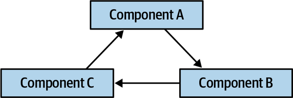
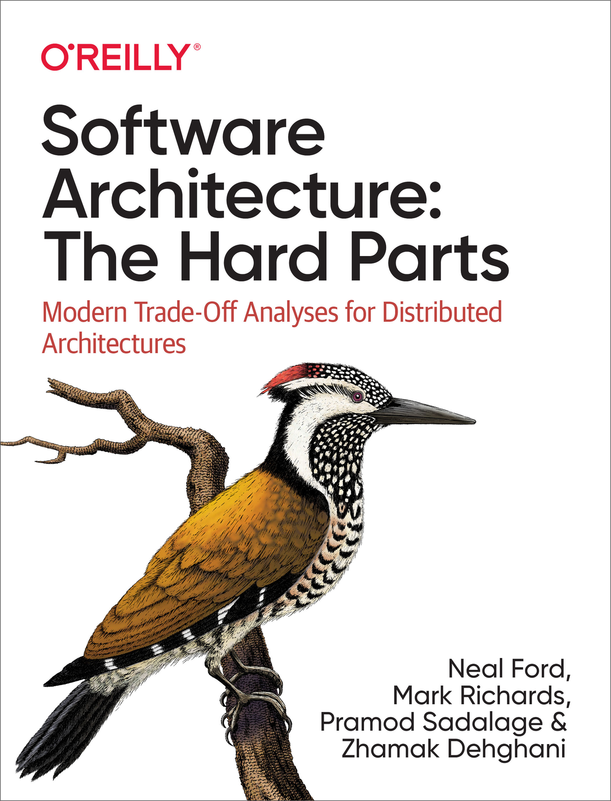
Figure 1-1. Cyclic dependencies between components
In this anti-pattern, each component references something in the others. Having a network of components such as this damages modularity because a developer cannot reuse a single component without also bringing the others along. And, of course, if the other components are coupled to other components, the architecture tends more and more toward the Big Ball of Mud anti-pattern. How can architects govern this behavior without constantly looking over the shoulders of trigger-happy developers? Code reviews help but happen too late in the development cycle to be effective. If an architect allows a development team to rampantly import across the codebase for a week until the code review, serious damage has already occurred in the codebase.
The solution to this problem is to write a fitness function to avoid component cycles, as shown in Example 1-1.
Example 1-1. Fitness function to detect component cycles
publicclassCycleTest{privateJDependjdepend;@BeforeEachvoidinit(){jdepend=newJDepend();jdepend.addDirectory("/path/to/project/persistence/classes");jdepend.addDirectory("/path/to/project/web/classes");jdepend.addDirectory("/path/to/project/thirdpartyjars");}@TestvoidtestAllPackages(){Collectionpackages=jdepend.analyze();assertEquals("Cycles exist",false,jdepend.containsCycles());}}
In the code, an architect uses the metrics tool JDepend to
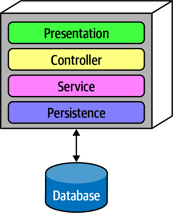
Figure 1-2. Traditional layered architecture
However, how can the architect ensure that developers will respect these layers? Some developers may not understand the importance of the patterns, while others may adopt a “better to ask forgiveness than permission” attitude because of some overriding local concern, such as performance. But allowing implementers to erode the reasons for the architecture hurts the long-term health of the architecture.
ArchUnit allows architects to address this problem via a fitness function, shown in Example 1-2.
Example 1-2. ArchUnit fitness function to govern layers
layeredArchitecture().layer("Controller").definedBy("..controller..").layer("Service").definedBy("..service..").layer("Persistence").definedBy("..persistence..").whereLayer("Controller").mayNotBeAccessedByAnyLayer().whereLayer("Service").mayOnlyBeAccessedByLayers("Controller").whereLayer("Persistence").mayOnlyBeAccessedByLayers("Service")
In Example 1-2, the architect defines the desirable relationship between layers and writes a verification fitness function to govern it. This allows an architect to establish architecture principles outside the diagrams and other informational artifacts, and verify them on an ongoing basis.
A similar tool in the .NET space,
Example 1-3. NetArchTest for layer dependencies
// Classes in the presentation should not directly reference repositoriesvarresult=Types.InCurrentDomain().That().ResideInNamespace("NetArchTest.SampleLibrary.Presentation").ShouldNot().HaveDependencyOn("NetArchTest.SampleLibrary.Data").GetResult().IsSuccessful;
Tools continue to appear in this space with increasing degrees of sophistication. We will continue to highlight many of these techniques as we illustrate fitness functions alongside many of our solutions.
Finding an objective outcome for a fitness function is critical.
Imagine an alternative world in which every project runs a deployment pipeline, and the security team has a “slot” in each team’s deployment pipeline where they can deploy fitness functions. Most of the time, these will be mundane checks for safeguards like preventing developers from storing passwords in databases and similar regular governance chores. However, when a zero-day exploit appears, having the same mechanism in place everywhere allows the security team to insert a test in every project that checks for a certain framework and version number; if it finds the dangerous version, it fails the build and notifies the security team. Teams configure deployment pipelines to awaken for any change to the ecosystem: code, database schema, deployment configuration, and fitness functions. This allows enterprises to universally automate important governance tasks.
Fitness functions provide many benefits for architects, not the least of which is the chance to do some coding again! One of the universal complaints among architects is that they don’t get to code much anymore—but fitness functions are often code! By building an executable specification of the architecture, which anyone can validate anytime by running the project’s build, architects must understand the system and its ongoing evolution well, which overlaps with the core goal of keeping up with the code of the project as it grows.
Architecture Versus Design: Keeping Definitions Simple
Second, by focusing on architecture concepts, we can avoid the numerous implementations of those concepts. Architects can implement asynchronous communication in a variety of ways; we focus on why an architect would choose asynchronous communication and leave the implementation details to another place.
Third, if we start down the path of implementing all the varieties of options we show, this would be the longest book ever written. Focus on architecture principles allows us to keep things as generic as they can be.
- Service
- In colloquial terms, a service is a cohesive collection of functionalitydeployed as an independent executable. Most of the concepts we discuss with regard to services apply broadly to distributed architectures, and specifically microservices architectures.In the terms we define inChapter 2, a service is part of an architecture quantum, which includes further definitions of both static and dynamic coupling between services and other quanta.
- Coupling
-
Two artifacts (including services) are coupled if a change in one might require a change in the other to maintain proper functionality.
- Component
- An architectural building block of the application that does some sort of business or infrastructure function,usually manifested through a package structure (Java), namespace (C#), or a physical grouping of source code files within some sort of directory structure. For example, the component Order History might be implemented through a set of class files located in the namespace
app.business.order.history. - Synchronous communication
- Two artifacts communicate synchronously if the caller must wait for the response before proceeding.
- Asynchronous communication
- Two artifacts communicate asynchronously if the caller does not wait for theresponse before proceeding. Optionally, the caller can be notified by the receiver through a separate channel when the request has completed.
- Orchestrated coordination
- A workflow is orchestrated if it includes a service whose primary responsibility is to coordinate the workflow.
- Choreographed coordination
- A workflow is choreographed when it lacks an orchestrator;rather, the services in the workflow share the coordination responsibilities of the workflow.
- Atomicty
- A workflow is atomic if all parts of the workflow maintain aconsistent state at all times; the opposite is represented by the spectrum of eventual consistency, covered inChapter 6.
- Contract
-
We use the term contract broadly to define the interface between two
software parts, which may encompass method or function calls, integration architecture remote calls, dependencies, and so on. Anywhere two pieces of software join, a contract is involved.
Introducing the Sysops Squad Saga
- saga
A long story of heroic achievement.
Oxford English Dictionary
We use the Sysops Squad saga within each chapter to illustrate the techniques and trade-offs described in this book. While many books on software architecture cover new development efforts, many real-world problems exist within existing systems. Therefore, our story starts with the existing Sysops Squad architecture highlighted here.
Penultimate Electronics is a large electronics giant that has numerous retail stores throughout the country. When customers buy computers, TVs, stereos, and other electronic equipment, they can choose to purchase a support plan. When problems occur, customer-facing technology experts (the Sysops Squad) come to the customer’s residence (or work office) to fix problems with the electronic device.
The four main users of the Sysops Squad ticketing application are as follows:
- Administrator
-
The administrator maintains the internal users of the system, including the list of experts and their corresponding skill set, location, and availability. The administrator also manages all of the billing processing for customers using the system, and maintains static reference data (such as supported products, name-value pairs in the system, and so on).
- Customer
-
The customer registers for the Sysops Squad service and maintains their customer profile, support contracts, and billing information. Customers enter problem tickets into the system, and also fill out surveys after the work has been completed.
- Sysops Squad expert
-
Experts are assigned problem tickets and fix problems based on the ticket. They also interact with the knowledge base to search for solutions to customer problems and enter notes about repairs.
- Manager
-
The manager keeps track of problem ticket operations and receives operational and analytical reports about the overall Sysops Squad problem ticket system.
Nonticketing Workflow
-
Sysops Squad experts are added and maintained in the system through an administrator, who enters in their locale, availability, and skills.
-
Customers register with the Sysops Squad system and have multiple support plans based on the products they purchased.
-
Customers are automatically billed monthly based on credit card information contained in their profile. Customers can view billing history and statements through the system.
-
Managers request and receive various operational and analytical reports, including financial reports, expert performance reports, and ticketing reports.
Ticketing Workflow
-
Customers who have purchased the support plan enter a problem ticket by using the Sysops Squad website.
-
Once a problem ticket is entered in the system, the system then determines which Sysops Squad expert would be the best fit for the job based on skills, current location, service area, and availability.
-
Once assigned, the problem ticket is uploaded to a dedicated custom mobile app on the Sysops Squad expert’s mobile device. The expert is also notified via a text message that they have a new problem ticket.
-
The customer is notified through an SMS text message or email (based on their profile preference) that the expert is on their way.
-
The expert uses the custom mobile application on their phone to retrieve the ticket information and location. The Sysops Squad expert can also access a knowledge base through the mobile app to find out what has been done in the past to fix the problem.
-
Once the expert fixes the problem, they mark the ticket as “complete.” The sysops squad expert can then add information about the problem and repair the knowledge base.
-
After the system receives notification that the ticket is complete, it sends an email to the customer with a link to a survey, which the customer then fills out.
-
The system receives the completed survey from the customer and records the survey information.
A Bad Scenario
Change is also difficult and risky in this large monolith. Whenever a change is made, it usually takes too long and something else usually breaks. Because of reliability issues, the Sysops Squad system frequently “freezes up,” or crashes, resulting in all application functionality not being available anywhere from five minutes to two hours while the problem is identified and the application restarted.
If something isn’t done soon, Penultimate Electronics will be forced to abandon the very lucrative support contract business line and lay off all the Sysops Squad administrators, experts, managers, and IT development staff—including the architects.
Sysops Squad Architectural Components
ss. part of the namespace specifies the Sysops Squad application context). 
Figure 1-3. Components within the existing Sysops Squad application
| Component | Namespace | Responsibility |
|---|---|---|
Login |
| Internal user and customer login and security logic |
Billing payment |
| Customer monthly billing and customer credit card info |
Billing history |
| Payment history and prior billing statements |
Customer notification |
| Notify customer of billing, general info |
Customer profile |
| Maintain customer profile, customer registration |
Expert profile |
| Maintain expert profile (name, location, skills, etc.) |
KB maint |
| Maintain and view items in the knowledge base |
KB search |
| Query engine for searching the knowledge base |
Reporting |
| All reporting (experts, tickets, financial) |
Ticket |
| Ticket creation, maintenance, completion, common code |
Ticket assign |
| Find an expert and assign the ticket |
Ticket notify |
| Notify customer that the expert is on their way |
Ticket route |
| Send the ticket to the expert’s mobile device app |
Support contract |
| Support contracts for customers, products in the plan |
Survey |
| Maintain surveys, capture and record survey results |
Survey notify |
| Send survey email to customer |
Survey templates |
| Maintain various surveys based on type of service |
User maintenance |
| Maintain internal users and roles |
These components will be used in subsequent chapters to illustrate various techniques and trade-offs when dealing with breaking applications into distributed architectures.
Sysops Squad Data Model
The Sysops Squad application with its various components listed in Table 1-1
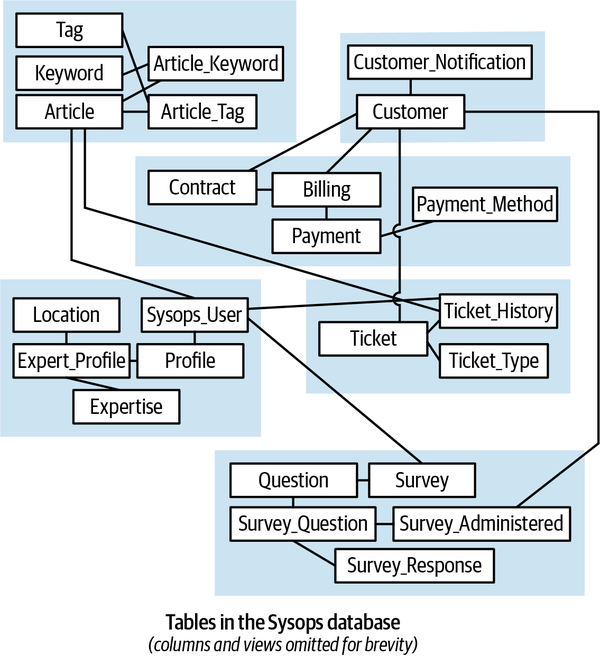
Figure 1-4. Data model within the existing Sysops Squad application
| Table | Responsibility |
|---|---|
Customer | Entities needing Sysops support |
Customer_Notification | Notification preferences for customers |
Survey | A survey for after-support customer satisfaction |
Question | Questions in a survey |
Survey_Question | A question is assigned to the survey |
Survey_Administered | Survey question is assigned to customer |
Survey_Response | A customer’s response to the survey |
Billing | Billing information for support contract |
Contract | A contract between an entity and Sysops for support |
Payment_Method | Payment methods supported for making payment |
Payment | Payments processed for billings |
SysOps_User | The various users in Sysops |
Profile | Profile information for Sysops users |
Expert_Profile | Profiles of experts |
Expertise | Various expertise within Sysops |
Location | Locations served by the expert |
Article | Articles for the knowledge base |
Tag | Tags on articles |
Keyword | Keyword for an article |
Article_Tag | Tags associated to articles |
Article_Keyword | Join table for keywords and articles |
Ticket | Support tickets raised by customers |
Ticket_Type | Different types of tickets |
Ticket_History | The history of support tickets |
The Sysops data model is a standard third normal form data model with only a few stored procedures or triggers. However, a fair number of views exist that are mainly used by the Reporting component. As the architecture team tries to break up the application and move toward distributed architecture, it will have to work with the database team to accomplish the tasks at the database level. This setup of database tables and views will be used throughout the book to discuss various techniques and trade-offs to accomplish the task of breaking apart the database.
Part I. Pulling Things Apart
As many of us discovered when we were children, a great way to understand how something fits together is to first pull it apart. To understand complex subjects (such as trade-offs in distributed architectures), an architect must figure out where to start untangling.
In the book What Every Programmer Should Know About Object-Oriented Design (Dorset House), Meilir Page-Jones
Our goal is to investigate how to do trade-off analysis in distributed architectures; to do that, we must pull the moving pieces apart so that we can discuss them in isolation to understand them fully before putting them back together.
Data and transactions have become increasingly important in architecture, driving many trade-off decisions by architects and DBAs. Chapter 6 addresses the architectural impacts of data, including how to reconcile service and data boundaries. Finally, Chapter 7 ties together architecture coupling with data concerns to define integrators and disintegrators—forces that encourage a larger or smaller service size and boundary.
Chapter 2. Discerning Coupling in Software Architecture
Wednesday, November 3, 13:00
Logan, the lead architect for Penultimate Electronics, interrupted a small group of architects in the cafeteria, discussing distributed architectures. “Austen, are you wearing a cast again?”
“No, it’s just a splint,” replied Austen. “I sprained my wrist playing extreme disc golf over the weekend—it’s almost healed.”
“What is…never mind. What is this impassioned conversation I barged in on?”
“Why wouldn’t someone always choose the saga pattern in microservices to wire together transactions?” asked Austen. “That way, architects can make the services as small as they want.”
“But don’t you have to use orchestration with sagas?” asked Addison. “What about times when we need asynchronous communication? And, how complex will the transactions get? If we break things down too much, can we really guarantee data fidelity?”
“You know,” said Austen, “if we use an enterprise service bus, we can get it to manage most of that stuff for us.”
“I thought no one used ESBs anymore—shouldn’t we use Kafka for stuff like that?”
“They aren’t even the same thing!” said Austen.
Logan interrupted the increasingly heated conversation. “It is an apples-to-oranges comparison, but none of these tools or approaches is a silver bullet. Distributed architectures like microservices are difficult, especially if architects cannot untangle all the forces at play. What we need is an approach or framework that helps us figure out the hard problems in our architecture.”
“Well,” said Addison, “whatever we do, it has to be as decoupled as possible—everything I’ve read says that architects should embrace decoupling as much as possible.”
“If you follow that advice,” said Logan, “Everything will be so decoupled that nothing can communicate with anything else—it’s hard to build software that way! Like a lot of things, coupling isn’t inherently bad; architects just have to know how to apply it appropriately. In fact, I remember a famous quote about that from a Greek philosopher….”
All things are poison, and nothing is without poison; the dosage alone makes it so a thing is not a poison.
Paracelsus
One of the most difficult tasks an architect will face is untangling the various forces and trade-offs at play in distibuted architectures.
Architects struggle with granularity and communication decisions because there are no clear universal guides for making decisions—no best practices exist that can apply to real-world complex systems. Until now, architects lacked the correct perspective and terminology to allow a careful analysis that could determine the best (or least worst) set of trade-offs on a case-by-case basis.
Why have architects struggled with decisions in distributed architectures? After all, we’ve been building distributed systems since the last century, using many of the same mechanisms (message queues, events, and so on). Why has the complexity ramped up so much with microservices?
This book focuses on how architects can perform trade-off analysis for any number of scenarios unique to their situation. As in many things in architecture, the advice is simple; the hard parts lie in the details, particularly how difficult parts become entangled, making it difficult to see and understand the individual parts, as illustrated in Figure 2-1.
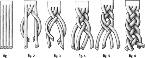
Figure 2-1. A braid entangles hair, making the individual strands hard to identify
When architects look at entangled problems, they struggle with performing trade-off analysis because of the difficulties separating the concerns, so that they may consider them independently. Thus, the first step in trade-off analysis is untangle the dimensions of the problem, analyzing what parts are coupled to one another and what impact that coupling has on change. For this purpose, we use the simplest definition of the word coupling:
- Coupling
-
Two parts of a software system are coupled if a change in one might cause a change in the other.
Often, software architecture creates multidimensional problems, where multiple forces all interact in interdependent ways. To analyze trade-offs, an architect must first determine what forces need to trade off with each other.
Thus, here’s our advice for modern trade-off analysis in software architecture:
-
Find what parts are entangled together.
-
Analyze how they are coupled to one another.
-
Assess trade-offs by determining the impact of change on interdependent systems.
While the steps are simple, the hard parts lurk in the details. Thus, to illustrate this framework in practice, we take one of the most difficult (and probably the closest to generic) problems in distributed architectures, which is related to microservices:
- How do architects determine the size and communication styles for microservices?
-
Determining the proper size for microservices seems a pervasive problem—too-small services create transactional and orchestration issues, and too-large services create scale and distribution issues.
To that end, the remainder of this book untangles the many aspects to consider when answering the preceding question. We provide new terminology to differentiate similar but distinct patterns and show practical examples of applying these and other patterns.
Architecture (Quantum | Quanta)
An architecture quantum measures several aspects of both topology and behavior in software architecture related to how parts connect and communicate with one another:
- Architecture quantum
- An architecture quantum is an independently deployable artifact with high functional cohesion,high static coupling, and synchronous dynamic coupling. A common example of an architecture quantum is a well-formed microservice within a workflow.
- Static coupling
- Represents how static dependencies resolve within the architecture viacontracts. These dependencies include operating system, frameworks, and/or libraries delivered via transitive dependency management, and any other operational requirement to allow the quantum to operate.
- Dynamic coupling
- Represents how quanta communicate at runtime, either synchronouslyor asynchronously. Thus, fitness functions for these characteristics must be continuous, typically utilizing monitors.
These definitions include important characteristics; let’s cover each in detail as they inform most of the examples in the book.
Independently Deployable
Making each architecture quantum represent a deployable asset within the architecture serves several useful purposes. First, the boundary represented by an architecture quantum serves as a useful common language among architects, developers, and operations. Each understands the common scope under question: architects understand the coupling characteristics, developers understand the scope of behavior, and the operations team understands the deployable characteristics.
Third, independent deployability forces the architecture quantum to include common coupling points such as databases. Most discussions about architecture conveniently ignore issues such as databases and user interfaces, but real-world systems must commonly deal with those problems. Thus, any system that uses a shared database fails the architecture quantum criteria for independent deployment unless the database deployment is in lockstep with the application. Many distributed systems that would otherwise qualify for multiple quanta fail the independently deployable part if they share a common database that has its own deployment cadence. Thus, merely considering the deployment boundaries doesn’t solely provide a useful measure. Architects should also consider the second criteria for an architecture quantum, high functional cohesion, to limit the architecture quantum to a useful scope.
High Functional Cohesion
High functional cohesion refers structurally to the proximity
High Static Coupling
An architecture quantum is, in part, a measure of static coupling, and the measure is quite simple for most architecture topologies. For example, the following diagrams show the architecture styles featured in Fundamentals of Software Architecture, with the architecture quantum static coupling illustrated.
Any of the monolithic architecture styles will necessarily have a
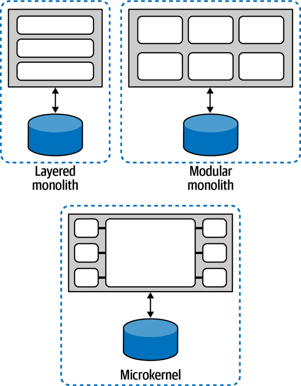
Figure 2-2. Monolithic architectures always have a quantum of one
As you can see, any architecture that deploys as a single unit and utilizes a single database will always have a single quantum. The architecture quantum measure of static coupling includes the database, and a system that relies on a single database cannot have more than a single quantum. Thus, the static coupling measure of an architecture quantum helps identify coupling points in architecture, not just within the software components under development. Most monolithic architectures contain a single coupling point (typically, a database) that makes its quantum measure one.
Distributed architectures often feature decoupling at the component level;
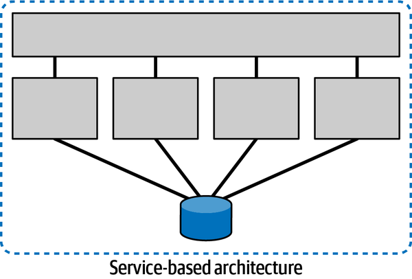
Figure 2-3. Architecture quantum for a service-based architecture
While this individual services model shows the isolation common in microservices, the architecture still utilizes a single relational database, rendering its architecture quantum score to one.
So far, the static coupling measurement of architecture quantum has evaluated all the topologies to one. However, distributed architectures create the possibility of multiple quanta but don’t necessarily guarantee it.
Even though this style represents a distributed architecture, two coupling points push it toward a single architecture quantum: the database, as common with the previous monolithic architectures, but also the Request Orchestrator itself—any holistic coupling point necessary for the architecture to function forms an architecture quantum around it.
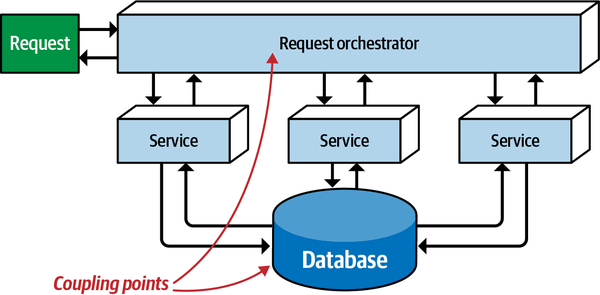
Figure 2-4. A mediated EDA has a single architecture quantum
Broker event-driven architectures (without a central mediator) are less coupled,
This broker-style event driven architecture (without a central mediator) is nevertheless a single architecture quantum because all the services utilize a single relational database, which acts as a common coupling point. The question answered by the static analysis for an architecture quantum is, “Is this dependent of the architecture necessary to bootstrap this service?” Even in the case of an event-driven architecture where some of the services don’t access the database, if they rely on services that do access the database, then they become part of the static coupling of the architecture quantum.
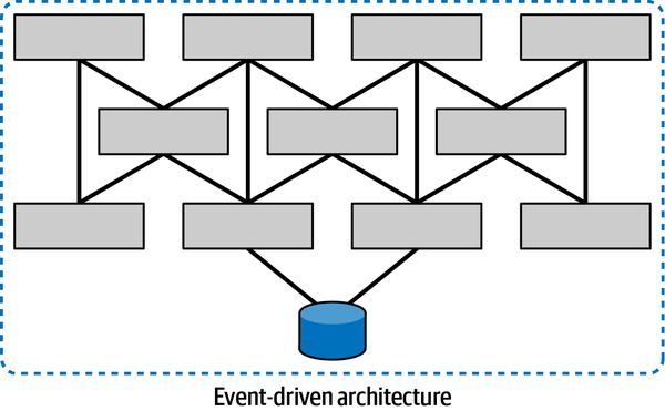
Figure 2-5. Even a distributed architecture such as broker-style event-driven architecture can be a single quantum
However, what about situations in distributed architectures where common coupling points don’t exist?
The architects designed this event-driven system
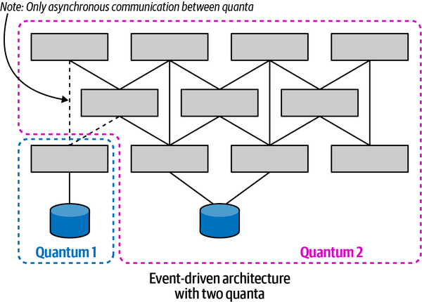
Figure 2-6. An event-driven architecture with multiple quanta
The microservices architecture style features
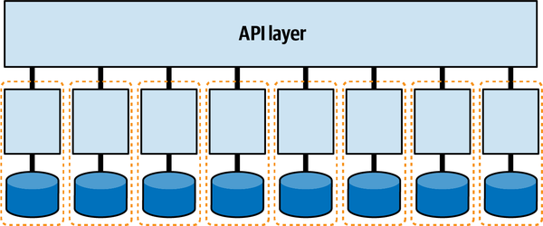
Figure 2-7. Microservices may form their own quanta
Each service (acting as a bounded context) may have its own set of architecture characteristics—one service might have higher levels of scalability or security than another. This granular level of architecture characteristics scoping represents one of the advantages of the microservices architecture style. High degrees of decoupling allow teams working on a service to move as quickly as possible, without worrying about breaking other dependencies.
However, if the system is tightly coupled to a user interface,
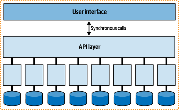
Figure 2-8. A tightly coupled user interface can reduce a microservices architecture quantum to one
User interfaces create coupling points between the front and back end, and most user interfaces won’t operate if portions of the backend aren’t available.
Additionally, it will be difficult for an architect to design different levels of operational architecture characteristics (performance, scale, elasticity, reliability, and so on) for each service if they all must cooperate together in a single user interface (particularly in the case of synchronous calls, covered in “Dynamic Quantum Coupling”).
Architects design user interfaces utilizing asynchronicity that doesn’t create coupling between front and back. A trend on many microservices projects is to use a micro frontend framework for user interface elements in a microservices architecture. In such an architecture, the user interface elements that interact on behalf of the services are emitted from the services themselves. The user interface surface acts as a canvas where the user interface elements can appear, and also facilitates loosely coupled communication between components, typically using events. Such an architecture is illustrated in Figure 2-9.
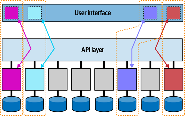
Figure 2-9. In a micro-frontend architecture, each service + user interface component forms an architecture quantum
In this example, the four tinted services along with their corresponding micro-frontends form architecture quanta: each of these services may have different architecture characteristics.
Any coupling point in an architecture can create static coupling points from a quantum standpoint. Consider the impact of a shared database between two systems, as illustrated in Figure 2-10.
The static coupling of a system provides valuable insight, even in complex systems involving integration architecture. Increasingly, a common architect technique for understanding legacy architecture involves creating a static quantum diagram of how things are “wired” together, which helps determine what systems will be impacted by change and offers a way of understanding (and potentially decoupling) the architecture.
Static coupling is only one-half of the forces at play in distributed architectures. The other is dynamic coupling.
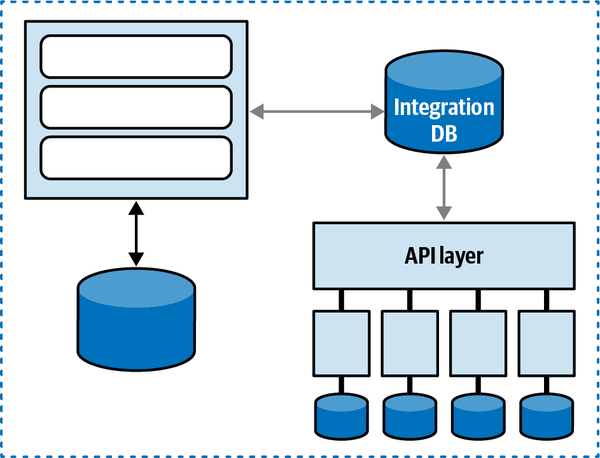
Figure 2-10. A shared database forms a coupling point between two systems, creating a single quantum
Dynamic Quantum Coupling
The nature of how services call one another creates difficult trade-off decisions because it represents a multidimensional decision space, influenced by three interlocking forces:
- Communication
-
Refers to the type of connection synchronicity used: synchronous or asynchronous.
- Consistency
-
Describes whether the workflow communication requires atomicity or can utilize eventual consistency.
- Coordination
-
Describes whether the workflow utilizes an orchestrator or whether the services communicate via choreography.
Communication
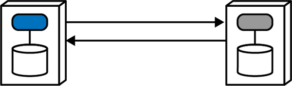
Figure 2-11. A synchronous call waits for a result from the receiver
The calling service makes a call (using one of a number of protocols that support synchronous calls, such as gRPC) and blocks (does no further processing) until the receiver returns a value (or status indicating a state change or error condition).
Asynchronous communication occurs between two services when the caller posts a message to the receiver (usually via a mechanism such as a message queue) and, once the caller gets acknowledgment that the message will be processed, it returns to work. If the request required a response value, the receiver can use a reply queue to (asynchronously) notify the caller of the result, which is illustrated in Figure 2-12.
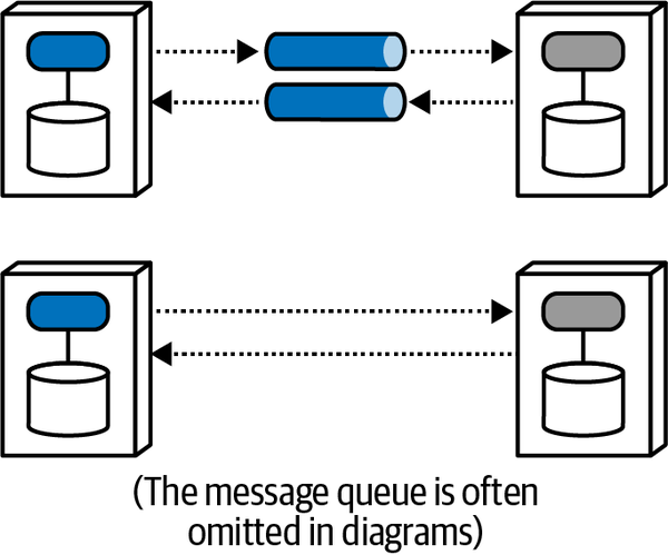
Figure 2-12. Asynchronous communication allows parallel processing
The caller posts a message to a message queue and continues processing until notified by the receiver that the requested information is available via return call. Generally, architects use message queues (illustrated via the gray cylindrical tube in the top diagram in Figure 2-12) to implement asynchronous communication, but queues are common and create noise on diagrams, so many architects leave them off, as shown in the lower diagram. And, of course, architects can implement asynchronous communication without message queues by using a variety of libraries or frameworks. Each diagram variety implies asynchronous messaging; the second provides visual shorthand and less implementation detail.
Architects must consider significant trade-offs when choosing how services will communicate. Decisions around communication affect synchronization, error handling, transactionality, scalability, and performance. The remainder of this book delves into many of these issues.
Consistency
Consistency refers to the strictness of transactional integrity
Coordination
Coordination refers to how much coordination the workflow
These three factors—communication, consistency, and coordination—all inform the important decision an architect must make. Critically, however, architects cannot make these choices in isolation; each option has a gravitation effect on the others. For example, transactionality is easier in synchronous architectures with mediation, whereas higher levels of scale are possible with eventually consistent asynchronous choreographed systems.
Thinking about these forces as related to each other forms a three-dimensional space, illustrated in
Each force in play during service communication appears as a dimension. For a particular decision, an architect could graph the position in space representing the strength of these forces.
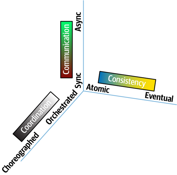
Figure 2-13. The dimensions of dynamic quantum coupling
When an architect can build a clear understanding of forces at play within a given situation,
| Pattern name | Communication | Consistency | Coordination | Coupling |
|---|---|---|---|---|
Epic Saga(sao) | synchronous | atomic | orchestrated | very high |
Phone Tag Saga(sac) | synchronous | atomic | choreographed | high |
Fairy Tale Saga(seo) | synchronous | eventual | orchestrated | high |
Time Travel Saga(sec) | synchronous | eventual | choreographed | medium |
Fantasy Fiction Saga(aao) | asynchronous | atomic | orchestrated | high |
Horror Story(aac) | asynchronous | atomic | choreographed | medium |
Parallel Saga(aeo) | asynchronous | eventual | orchestrated | low |
Anthology Saga(aec) | asynchronous | eventual | choreographed | very low |
To fully understand this matrix, we must first investigate each of the dimensions individually. Therefore, the following chapters help you build context to understand the individual trade-offs for communication, consistency, and coordination, then entangle them back together in Chapter 12.
Sysops Squad Saga: Understanding Quanta
Tuesday, November 23, 14:32
Austen came to Addison’s office wearing an uncharacteristic cross expression.
“Sure, what’s up?”
“I’ve been reading about this architecture quantum stuff, and I just…don’t…get…it!”
Addison laughed, “I know what you mean. I struggled with it when it was purely abstract, but when you ground it in practical things, it turns out to be a useful set of perspectives.”
“What do you mean?”
“Why not just use bounded context, then?” asked Austen.
“What is that all about? Isn’t coupling just coupling? Why make the distinction?”
“It turns out that a bunch of different concerns revolve around the different types,” said Addison. “Let’s take the static one first, which I like to think of as how things are wired together. Another way to think about it: consider one of the services we’re building in our target architecture. What is all the wiring required to bootstrap that service?”
“Well, it’s written in Java, using a Postgres database, and running in Docker—that’s it, right?”
“You’re missing a lot.” said Addison. “What if you had to build that service from scratch, assuming we had nothing in place? It’s Java, but also using SpringBoot and, what, about 15 or 20 different frameworks and libraries?”
“That’s right, we can look in the Maven POM file to figure out all those dependencies. What else?”
“But isn’t that the dynamic part?”
“Not the presence of the broker. If the service (or, more broadly, architecture quantum) I want to bootstrap utilizes a message broker to function, the broker must be present. When the service calls another service via the broker, we get into the dynamic side.”
“OK, that makes sense,” said Austen. “If I think about what it would take to bootstrap it from scratch, that’s the static quantum coupling.”
“That’s right. And just that information is super useful. We recently built a diagram of the static quantum coupling for each of our services defensively.”
Austen laughed. “Defensively? What do you…”
“We were performing a reliability analysis to determine if I change this thing, what might break, where thing could be anything in our architecture or operations. They’re trying to do risk mitigation—if we change a service, they want to know what must be tested.”
“I see—that’s the static quantum coupling. I can see how that’s a useful view. It also shows how teams might impact one another. That seems really useful. Is there a tool we can download that figures that out for us?”
“Wouldn’t that be nice!” laughed Addison. “Unfortunately, no one with our unique mix of architecture has built and open sourced exactly the tool we want. However, some of the platform team is working on a tool to automate it, necessarily customized to our architecture. They’re using the container manifests, POM files, NPM dependencies, and other dependency tools to build and maintain a list of build dependencies. We have also instituted observability for all our services, so we now have consistent log files about what systems call each other, when, and how often. They’re using that to build a call graph to see how things are connected.”
“OK, so static coupling is how things are wired together. What about dynamic coupling?”
“Oh, I see, I see! The architecture quantum defines the scope of architecture characteristics—it’s obvious how the static coupling can affect that. But I see now that, depending on the type of call you make, you might temporarily couple two services together.”
“That’s right,” said Addison. “The architecture quanta can entangle one another temporarily, during the course of a call, if the nature of the call ties things like performance, responsiveness, scale, and a bunch of others.”
“OK, I think I understand what an architecture quantum is, and how the coupling definitions work. But I’m never going to get that quantum/quanta thing straight!”
“Same for datum/data, but no one ever uses datum!” laughed Addison. “You’ll see a lot more of the impact of dynamic coupling on workflows and transactional sagas as you keep digging into our architecture.”
“I can’t wait!”
Chapter 3. Architectural Modularity
Tuesday, September 21 09:33
It was the same conference room they had been in a hundred times before, but today the atmosphere was different.
The business leaders and sponsors of the failing Sysops Squad ticketing application met with the application architects, Addison and Austen, with the purpose of voicing their concern and frustration about the inability of the IT department to fix the never-ending issues associated with the trouble ticket application. “Without a working application,” they had said, “we cannot possibly continue to support this business line.”
As the tense meeting ended, the business sponsors quietly filed out one by one, leaving Addison and Austen alone in the conference room.
“That was a bad meeting,” said Addison. “I can’t believe they’re actually blaming us for all the issues we’re currently facing with the trouble ticket application. This is a really bad situation.”
“Yeah, I know,” said Austen. “Especially the part about possibly closing down the product support business line. We’ll be assigned to other projects, or worse, maybe even let go. Although I’d rather be spending all of my time on the soccer field or on the slopes skiing in the winter, I really can’t afford to lose this job.”
“Neither can I,” said Addison. “Besides, I really like the development team we have in place, and I’d hate to see it broken up.”
“Me too,” said Austen. “I still think breaking apart the application would solve most of these issues.”
“I agree with you,” said Addison, “but how do we convince the business to spend more money and time to refactor the architecture? You saw how they complained in the meeting about the amount of money we’ve already spent applying patches here and there, only to create additional issues in the process.”
“You’re right,” Austen said. “They would never agree to an expensive and time-consuming architecture migration effort at this point.”
“But if we both agree that we need to break apart the application to keep it alive, how in the world are we going to convince the business and get the funding and time we need to completely restructure the Sysops Squad application?” asked Addison.
“Beats me,” said Austen. “Let’s see if Logan is available to discuss this problem with us.”
Addison looked online and saw that Logan, the lead architect for Penultimate Electronics, was available. Addison sent a message explaining that they wanted to break apart the existing monolithic application, but weren’t sure how to convince the business that this approach would work. Addison explained in the message that they were in a real bind and could use some advice. Logan agreed to meet with them and joined them in the conference room.
“What makes you so sure that breaking apart the Sysops Squad application will solve all of the issues?” asked Logan.
“Because,” said Austen, “we’ve tried patching the code over and over, and it doesn’t seem to be working. We still have way too many issues.”
“You’re completely missing my point,” said Logan. “Let me ask you the question a different way. What assurances do you have that breaking apart the system will accomplish anything more than just spending more money and wasting more valuable time?”
“Well,” said Austen, “actually, we don’t.”
“Then how do you know breaking apart the application is the right approach?” asked Logan.
“We already told you,” said Austen, “because nothing else we try seems to work!”
“Sorry,” said Logan, “but you know as well as I do that’s not a reasonable justification for the business. You’ll never get the funding you need with that kind of reason.”
“So, what would be a good business justification?” asked Addison. “How do we sell this approach to the business and get the additional funding approved?”
“Well,” said Logan, “to build a good business case for something of this magnitude, you first need to understand the benefits of architectural modularity, match those benefits to the issues you are facing with the current system, and finally analyze and document the trade-offs involved with breaking apart the application.”
It’s difficult in today’s world to manage all of this constant and rapid change with respect to software architecture. Software architecture is the foundational structure of a system, and is therefore generally thought of as something that should remain stable and not undergo frequent change, similar to the underlying structural aspects of a large building or skyscraper. However, unlike the structural architecture of a building, software architecture must constantly change and adapt to meet the new demands of today’s business and technology environment.

Figure 3-1. A full glass representing a large monolithic application close to capacity
One aspect of architectural modularity is
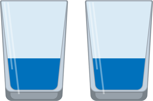
Figure 3-2. Two half-full glasses representing an application broken apart with plenty of capacity for growth
Increased scalability is only one benefit of architectural modularity.
There is one thing that will separate the pack into winners and losers: the on-demand capability to make bold and decisive course-corrections that are executed effectively and with urgency.
Businesses must be agile in order to survive in today’s world. However, while business stakeholders may be able to make quick decisions and change direction quickly, the company’s technology staff may not be able to implement those new directives fast enough to make a difference. Enabling technology to move as fast as the business (or, conversely, preventing technology from slowing the business) requires a certain level of architectural agility.
Modularity Drivers
Businesses must be agile to survive in today’s fast-paced and ever-changing
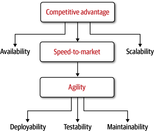
Figure 3-3. The drivers for modularity and the relationships among them
Note that architectural modularity does not always have to
Maintainability
Maintainability is about the ease of adding, changing, or removing features,
where ML is the maintainability level of the overall system (percentage from 0% to 100%), k is the total number of logical components in the system, and ci is the coupling level for any given component, with a special focus on incoming coupling levels. This equation basically demonstrates that the higher the incoming coupling level between components, the lower the overall maintainability level of the codebase.
Putting aside complicated mathematics, some of the typical metrics used for determining the relative maintainability of an application based on components (the architectural building blocks of an application) include the following:
- Component coupling
-
The degree and manner to which components know about one another
- Component cohesion
- The degree and manner to which the operations of a component interrelate
- Cyclomatic complexity
- The overall level of indirection and nesting within a component
- Component size
-
The number of aggregated statements of code within a component
- Technical versus domain partitioning
- Components aligned by technical usage or by domainpurpose—seeAppendix A
Within the context of architecture, we are
app.business.order.history.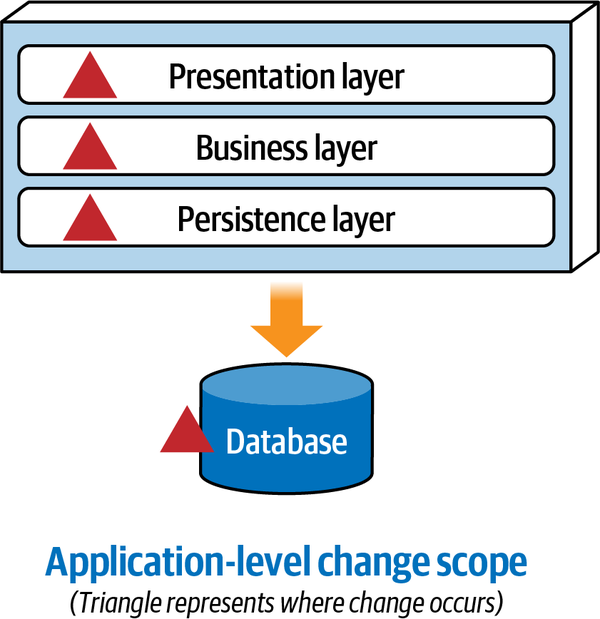
Figure 3-4. With monolithic layered architectures, change is at an application level
Depending on the team structure, implementing this simple change to add an expiration date to wish list items in a monolithic layered architecture could possibly require the coordination of at least three teams:
-
A member from the user interface team would be needed to add the new expiry field to the screen.
-
A member from the backend team would be needed to add business rules associated with the expiry date and change contracts to add the new expiry field.
-
A member from the database team would be needed to change the table schema to add the new expiry column in the Wishlist table.
Since the Wishlist domain is spread throughout the entire architecture, it becomes harder to maintain a particular domain or subdomain (such as Wishlist). Modular architectures, on the other hand, partition domains and subdomains into smaller, separately deployed units of software, thereby making it easier to modify a domain or subdomain. Notice that with a distributed service-based architecture, as shown in Figure 3-5, the change scope of the new requirement is at a domain level within a particular domain service, making it easier to isolate the specific deployment unit requiring the change.
Moving to even more architectural modularity
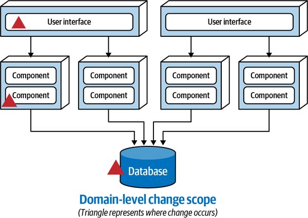
Figure 3-5. With service-based architectures, change is at a domain level
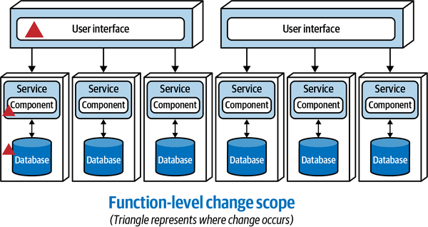
Figure 3-6. With microservices architectures, change is at a function level
These three progressions toward modularity demonstrate that as the level of architectural modularity increases, so does maintainability, making it easier to add, change, or remove functionality.
Testability
Making a change to Service A limits the testing scope to only that service, since Service B and Service C are not coupled to Service A. However, as communication increases among these services, as shown at the bottom of Figure 3-7, testability declines rapidly because the testing scope for a change to Service A now includes Service B and Service C, therefore impacting both the ease of testing and the completeness of testing.
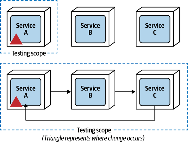
Figure 3-7. Testing scope is increased as services communicate with one another
Deployability
Deployability is not only about the ease of deployment—it is also about
If your microservices must be deployed as a complete set in a specific order, please put them back in a monolith and save yourself some pain.
This scenario leads to what is commonly referred to as the “big ball of distributed mud,” where very few (if any) of the benefits of architectural modularity are realized.
Scalability
Scalability is defined as the ability of a system to remain
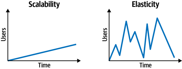
Figure 3-8. Scalability is different from elasticity
While both of these architectural characteristics include responsiveness as a function of the number of concurrent requests (or users in the system), they are handled differently from an architectural and implementation standpoint. Scalability generally occurs over a longer period of time as a function of normal company growth, whereas elasticity is the immediate response to a spike in user load.
A great example to further illustrate the difference is that of a concert-ticketing system. Between major concert events, there is usually a fairly light concurrent user load. However, the minute tickets go on sale for a popular concert, concurrent user load significantly spikes. The system may go from 20 concurrent users to 3,000 concurrent users in a matter of seconds. To maintain responsiveness, the system must have the capacity to handle the high peaks in user load, and also have the ability to instantaneously start up additional services to handle the spike in traffic.
Notice that scalability and elasticity rate relatively low with the monolithic layered architecture. Large monolithic layered architectures are both difficult and expensive to scale because all of the application functionality must scale to the same degree (application-level scalability and poor MTTS). This can become particularly costly in cloud-based infrastructures.
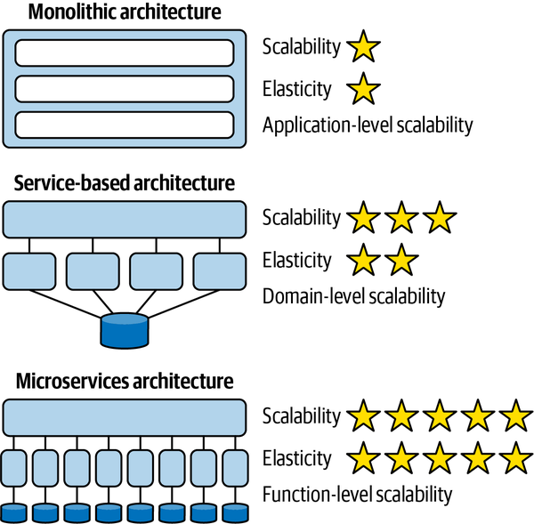
Figure 3-9. Scalability and elasticity improve with modularity
Availability/Fault Tolerance
Sysops Squad Saga: Creating a Business Case
Thursday, September 30, 12:01
“Let’s take each of the issues we are facing and see if we can match them to some of the modularity drivers,” said Addison. “That way, we can demonstrate to the business that breaking apart the application will in fact address the issues we are facing.”
“Good idea,” said Austen. “Let’s start with the first issue they talked about in the meeting—change. We cannot seem to effectively apply changes to the existing monolithic system without something else breaking. Also, changes take way too long, and testing the changes is a real pain.”
“And the developers are constantly complaining that the codebase is too large, and it’s difficult to find the right place to apply changes to new features or bug fixes,” said Addison.
“OK,” said Austen, “so clearly, overall maintainability is a key issue here.”
“Right,” said Addison. “So, by breaking apart the application, it would not only decouple the code, but it would isolate and partition the functionality into separately deployed services, making it easier for developers to apply changes.”
“Testability is another key characteristic related to this problem, but we have that covered already because of all our automated unit tests,” said Austen.
“Actually, it’s not,” replied Addison. “Take a look at this.”
Addison showed Austen that over 30% of the test cases are commented out or obsolete, and there are missing test cases for some of the critical workflow parts of the system. Addison also explained that the developers were continually complaining that the entire unit test suite had to be run for any change (big or small), which not only took a long time, but developers were faced with having to fix issues not related to their change. This was one of the reasons it was taking so long to apply even the simplest of changes.
“Testability is about the ease of testing, but also the completeness of testing,” said Addison. “We have neither. By breaking apart the application, we can significantly reduce the scope of testing for changes made to the application, group relevant automated unit tests together, and get better completeness of testing—hence fewer bugs.”
“The same is true with deployability,” continued Addison. “Because we have a monolithic application, we have to deploy the entire system, even for a small bug fix. Because our deployment risk is so high, Parker insists on doing production releases on a monthly basis. What Parker doesn’t understand is that by doing so, we pile multiple changes onto every release, some of which haven’t even been tested in conjunction with each other.”
“I agree,” said Austen, “and besides, the mock deployments and code freezes we do for each release take up valuable time—time we don’t have. However, what we’re talking about here is not an architecture issue, but purely a deployment pipeline issue.”
“I disagree,” said Addison. “It’s definitely architecture related as well. Think about it for a minute, Austen. If we broke the system into separately deployed services, then a change for any given service would be scoped to that service only. For example, let’s say we make yet another change to the ticket assignment process. If that process was a separate service, not only would the testing scope be reduced, but we would significantly reduce the deployment risk. That means we could deploy more frequently with much less ceremony, as well as significantly reduce the number of bugs.”
“I see what you mean,” said Austen, “and while I agree with you, I still maintain that at some point we will have to modify our current deployment pipeline as well.”
Satisfied that breaking apart the Sysops Squad application and moving to a distributed architecture would address the change issues, Addison and Austen moved on to the other business sponsor concerns.
“OK,” said Addison, “the other big thing the business sponsors complained about in the meeting was overall customer satisfaction. Sometimes the system isn’t available, the system seems to crash at certain times during the day, and we’ve experienced too many lost tickets and ticket routing issues. It’s no wonder customers are starting to cancel their support plans.”
“Hold on,” said Austen. “I have some latest metrics here that show it’s not the core ticketing functionality that keeps bringing the system down, but the customer survey functionality and reporting.”
“This is excellent news,” said Addison. “So by breaking apart that functionality of the system into separate services, we can isolate those faults, keeping the core ticketing functionality operational. That’s a good justification in and of itself!”
“Exactly,” said Austen. “So, we are in agreement then that overall availability through fault tolerance will address the application not always being available for the customers since they only interact with the ticketing portion of the system.”
“But what about the system freezing up?” asked Addison. “How do we justify that part with breaking up the application?”
“It just so happens I asked Sydney from the Sysops Squad development team to run some analysis for me regarding exactly that issue,” said Austen. “It turns out that it is a combination of two things. First, whenever we have more than 25 customers creating tickets at the same time, the system freezes. But, check this out—whenever they run the operational reports during the day when customers are entering problem tickets, the system also freezes up.”
“So,” said Addison, “it appears we have both a scalability and a database load issue here.”
“Exactly!” Austen said. “And get this—by breaking up the application and the monolithic database, we can segregate reporting into its own system and also provide the added scalability for the customer-facing ticketing functionality.”
Satisfied that they had a good business case to present to the business sponsors and confident that this was the right approach for saving this business line, Addison created an Architecture Decision Record (ADR) for the decision to break apart the system and create a corresponding business case presentation for the business sponsors.
ADR: Migrate Sysops Squad Application to a Distributed Architecture
Context
The Sysops Squad is currently a monolithic problem ticket application that supports many different business functions related to problem tickets, including customer registration, problem ticket entry and processing, operations and analytical reporting, billing and payment processing, and various administrative maintenance functions. The current application has numerous issues involving scalability, availability, and maintainability.Decision
We will migrate the existing monolithic Sysops Squad application to a distributed architecture. Moving to a distributed architecture will accomplish the following:
Make the core ticketing functionality more available for our external customers, therefore providing better fault tolerance
Provide better scalability for customer growth and ticket creation, resolving the frequent application freeze-ups we’ve been experiencing
Separate the reporting functionality and reporting load on the database, resolving the frequent application freeze-ups we’ve been experiencing
Allow teams to implement new features and fix bugs much faster than with the current monolithic application, therefore providing for better overall agility
Reduce the amount of bugs introduced into the system when changes occur, therefore providing better testability
Allow us to deploy new features and bug fixes at a much faster rate (weekly or even daily), therefore providing better deployability
Consequences
The migration effort will cause delays for new features being introduced since most of the developers will be needed for the architecture migration.The migration effort will incur additional cost (cost estimates to be determined).
Until the existing deployment pipeline is modified, release engineers will have to manage the release and monitoring of multiple deployment units.
The migration effort will require us to break apart the monolithic database.
Chapter 4. Architectural Decomposition
Monday, October 4, 10:04
Now that Addison and Austen had the go-ahead to move to a distributed architecture
“The application is so big I don’t even know where to start. It’s as big as an elephant!” exclaimed Addison.
“Well,” said Austen. “How do you eat an elephant?”
“Ha, I’ve heard that joke before, Austen. One bite at a time, of course!” laughed Addison.
“Exactly. So let’s use the same principle with the Sysops Squad application,” said Austen. “Why don’t we just start breaking it apart, one bite at a time? Remember how I said reporting was one of the things causing the application to freeze up? Maybe we should start there.”
“That might be a good start,” said Addison, “but what about the data? Just making reporting a separate service doesn’t solve the problem. We’d need to break apart the data as well, or even create a separate reporting database with data pumps to feed it. I think that’s too big of a bite to take starting out.”
“You’re right,” said Austen. “Hey, what about the knowledge base functionality? That’s fairly standalone and might be easier to extract.”
“That’s true. And what about the survey functionality? That should be easy to separate out as well,” said Addison. “The problem is, I can’t help feeling like we should be tackling this with more of a methodical approach rather than just eating the elephant bite by bite.”
“Maybe Logan can give us some advice,” said Austen.
Addison and Austen met with Logan to discuss some of the approaches they were considering for how to break apart the application. They explained to Logan that they wanted to start with the knowledge base and survey functionality but weren’t sure what to do after that.
“The approach you’re suggesting,” said Logan, “is what is known as the Elephant Migration Anti-Pattern. Eating the elephant one bite at a time may seem like a good approach at the start, but in most cases it leads to an unstructured approach that results in a big ball of distributed mud, what some people also call a distributed monolith. I would not recommend that approach.”
“So, what other approaches exist? Are there patterns we can use to break apart the application?” asked Addison.
“You need to take a holistic view of the application and apply either tactical forking or component-based decomposition,” said Logan. “Those are the two most effective approaches I know of.”
Addison and Austen looked at Logan. “But how do we know which one to use?”
Which approach is most effective? The answer to this question is, of course, it depends. One of the main factors in selecting a decomposition approach is how well the existing monolithic application code is structured. Do clear components and component boundaries exist within the codebase, or is the codebase largely an unstructured big ball of mud?
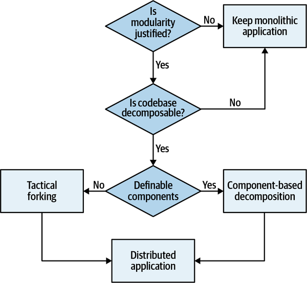
Figure 4-1. The decision tree for selecting a decomposition approach
We describe both of these approaches in this chapter, and then devote an entire chapter (Chapter 5) to describing each of the component-based decomposition patterns in detail.
Is the Codebase Decomposable?
What happens when a codebase lacks internal structure?
Unfortunately, without careful governance, many software systems degrade into big balls of mud, leaving it to subsequent architects (or perhaps a despised former self) to repair. Step one in any architecture restructuring exercise requires an architect to determine a plan for the restructuring, which in turn requires the architect to understand the internal structure. The key question the architect must answer becomes is this codebase salvageable? In other words, is it a candidate for decomposition patterns, or is another approach more appropriate?
No single measure will determine whether a codebase has reasonable internal structure—that evaluation falls to one or more architects to determine. However, architects do have tools to help determine macro characteristics of a codebase, particularly coupling metrics, to help evaluate internal structure.
Afferent and Efferent Coupling
In 1979, Edward Yourdon and Larry Constantine published
Note the value of just these two measures when changing the structure of a system. For example, when deconstructing a monolith into a distributed architecture, an architect will find shared classes such as Address. When building a monolith, it is common and encouraged for developers to reuse core concepts such as Address, but when pulling the monolith apart, now the architect must determine how many other parts of the system use this shared asset.
In this example, the Eclipse plug-in provides
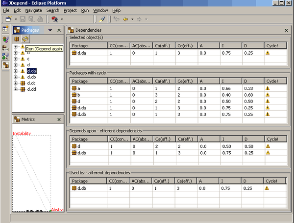
Figure 4-2. JDepend in Eclipse analysis view of coupling relationships
Abstractness and Instability
Abstractness is the ratio of abstract artifacts (abstract classes, interfaces, and so on) to concrete artifacts (implementation classes). It represents a measure of abstract versus implementation. Abstract elements are features of a codebase that allow developers to understand the overall function better. For example, a codebase consisting of a single main() method and 10,000 lines of code would score nearly zero on this metric and be quite hard to understand.
Equation 4-1. Abstractness
In the equation, represents abstract elements (interfaces or abstract classes) within the codebase, and represents concrete elements. Architects calculate abstractness by calculating the ratio of the sum of abstract artifacts to the sum of the concrete ones.
Another derived metric, instability, is the
Equation 4-2. Instability
In the equation, represents efferent (or outgoing)
The instability metric determines the volatility of a codebase. A codebase that exhibits high degrees of instability breaks more easily when changed because of high coupling. Consider two scenarios, each with of 2. For the first scenario, = 0, yielding an instability score of zero. In the other scenario, = 3, yielding an instability score of 3/5. Thus, the measure of instability for a component reflects how many potential changes might be forced by changes to related components. A component with an instability value near one is highly unstable, a value close to zero may be either stable or rigid: it is stable if the module or component contains mostly abstract elements, and rigid if it comprises mostly concrete elements. However, the trade-off for high stability is lack of reuse—if every component is self contained, duplication is likely.
A component with an I value close to 1, we can agree, is highly instable. However, a component with a value of I close to 0 may be either stable or rigid. However, if it contains mostly concrete elements, then it is rigid.
Thus, in general, it is important to look at the value of I and A together rather than in isolation. Hence the reason to consider the main sequence presented on the next page.
Distance from the Main Sequence
Equation 4-3. Distance from the main sequence
In the equation, A = abstractness and I = instability.
The distance-from-the-main-sequence metric imagines an ideal relationship between abstractness and instability; components that fall near this idealized line exhibit a healthy mixture of these two competing concerns. For example, graphing a particular component allows developers to calculate the distance-from-the-main-sequence metric, illustrated in Figure 4-3.
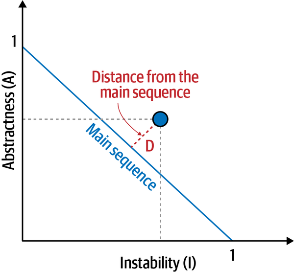
Figure 4-3. Normalized distance from the main sequence for a particular component
Developers graph the candidate component, then measure the distance from the idealized line. The closer to the line, the better balanced the component.
Tools exist in many platforms to provide these measures, which assist architects when analyzing codebases because of unfamiliarity, migration, or technical debt assessment.
What does the distance-from-the-main-sequence metric tell architects looking to restructure applications? Just as in construction projects, moving a large structure that has a poor foundation presents risks. Similarly, if an architect aspires to restructure an application, improving the internal structure will make it easier to move the entity.
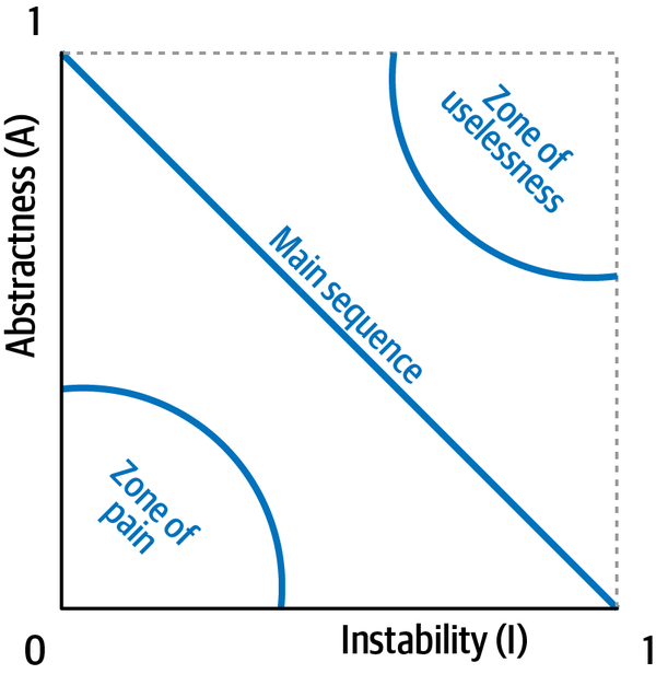
Figure 4-4. Zones of uselessness and pain
This metric also provides a good clue as to the balance of the internal structure. If an architect evaluates a codebase where many of the components fall into either the zones of uselessness or pain, perhaps it is not a good use of time to try to shore up the internal structure to the point where it can be repaired.
Following the flowchart in Figure 4-1, once an architect decides that the codebase is decomposable, the next step is to determine what approach to take to decompose the application. The following sections describe the two approaches for decomposing an application: component-based decomposition and tactical forking.
Component-Based Decomposition
It has been our experience that most of the difficulty and complexity involved
penultimate.ss.ticket.assign. 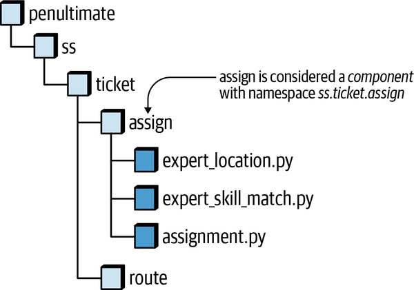
Figure 4-5. The directory structure of a codebase becomes the namespace of the component
Tip
When breaking monolithic applications into distributed
These component-based decomposition patterns essentially enable the migration of a monolithic architecture to a service-based architecture, which is defined in Chapter 2 and described in more detail in Fundamentals of Software Architecture.
- As a stepping-stone, it allows an architect to determine which domains require further levels of granularity into microservices and which ones can remain as coarse-grained domain services (this decision is discussed in detail inChapter 7).
-
Service-based architecture does not require the database to be broken apart, therefore allowing architects to focus on the domain and functional partitioning prior to tackling database decomposition (discussed in detail in Chapter 6).
-
Service-based architecture does not require any operational automation or containerization. Each domain service can be deployed using the same deployment artifact as the original application (such as an EAR file, WAR file, Assembly, and so on).
-
The move to service-based architecture is a technical one, meaning it generally doesn’t involve business stakeholders and doesn’t require any change to the organization structure of the IT department nor the testing and deployment environments.
Tip
When migrating monolithic applications to microservices, consider moving to a service-based architecture first as a stepping-stone to microservices.
Tactical Forking
Generally, when architects think about restructuring a codebase, they think of extracting pieces, as illustrated in Figure 4-6.
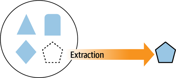
Figure 4-6. Extracting a part of a system
However, another way to think of isolating one part of a system involves deleting the parts no longer needed, as illustrated in Figure 4-7.
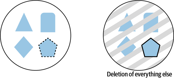
Figure 4-7. Deleting what’s not wanted is another way to isolate parts of a system
In Figure 4-6, developers have to constantly deal with the exuberant strands of coupling that define this architecture; as they extract pieces, they discover that more and more of the monolith must come along because of dependencies. In Figure 4-7, developers delete what code isn’t needed, but the dependencies remain, avoiding the constant unraveling effect of extraction.
The difference between extraction and deletion inspires the tactical forking pattern. For this decomposition approach, the system starts as a single monolithic application, as shown in Figure 4-8.
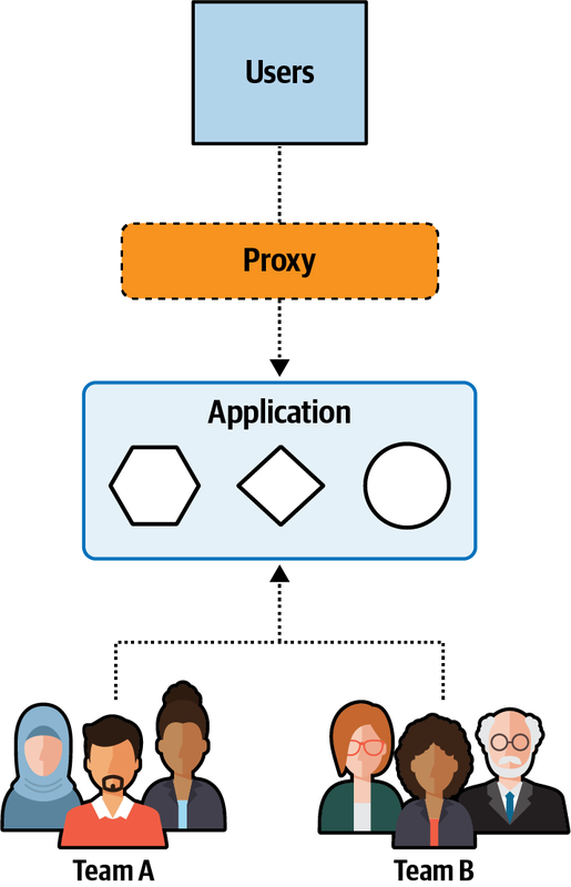
Figure 4-8. Before restructuring, a monolith includes several parts
This system consists of several domain behaviors (identified in the figure as simple geometric shapes) without much internal organization. In addition, in this scenario, the desired goal consists of two teams to create two services, one with the hexagon and square domain, and another with the circle domain, from the existing monolith.
The first step in tactical forking involves cloning the entire monolith, and giving each team a copy of the entire codebase, as illustrated in Figure 4-9.
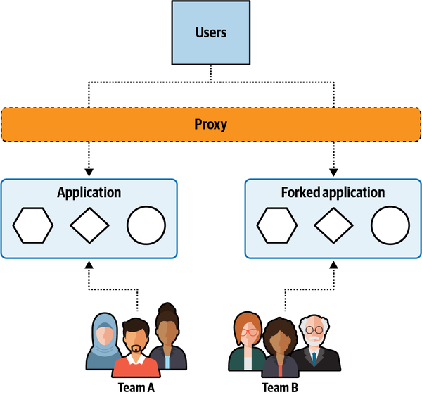
Figure 4-9. Step one clones the monolith
Each team receives a copy of the entire codebase, and they start deleting (as illustrated previously in Figure 4-7) the code they don’t need rather than extract the desirable code. Developers often find this easier in a tightly coupled codebase because they don’t have to worry about extracting the large number of dependencies that high coupling creates. Rather, in the deletion strategy, once functionality has been isolated, delete any code that doesn’t break anything.
As the pattern continues to progress, teams begin to isolate the target portions, as shown in Figure 4-10. Then each team continues the gradual elimination of unwanted code.
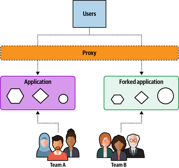
Figure 4-10. Teams constantly refactor to remove unwanted code
At the completion of the tactical forking pattern, teams have split the original monolithic application into two parts, preserving the coarse-grained structure of the behavior in each part, as illustrated in Figure 4-11.
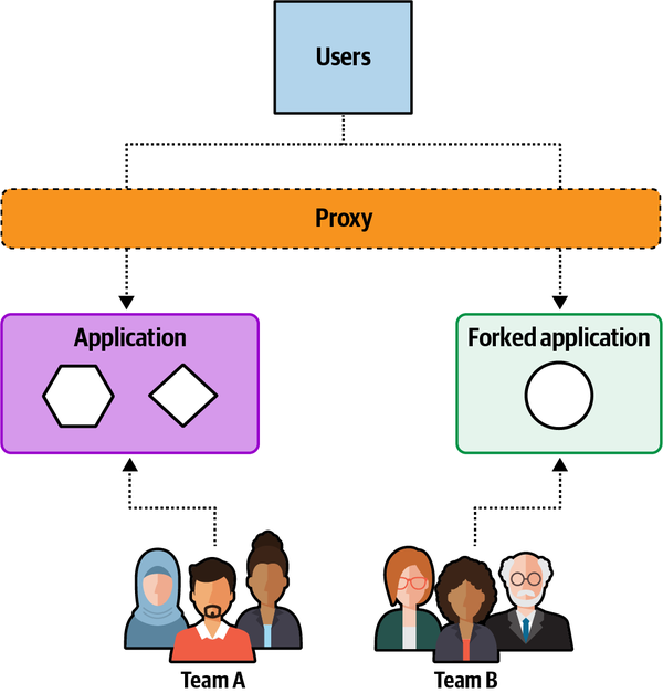
Figure 4-11. The end state of tactical forking features two services
Now the restructuring is complete, leaving two coarse-grained services as the result.
Trade-Offs
Tactical forking is a viable alternative to a more formal
- Benefits
-
-
Teams can start working right away with virtually no up-front analysis.
-
Developers find it easier to delete code rather than extract it. Extracting code from a chaotic codebase presents difficulties because of high coupling, whereas code not needed can be verified by compilation or simple testing.
-
- Shortcomings
-
-
The resulting services will likely still contain a large amount of mostly latent code left over from the monolith.
-
Unless developers undertake additional efforts, the code inside the newly derived services won’t be better than the chaotic code from the monolith—there’s just less of it.
-
Inconsistencies may occur between the naming of shared code and shared component files, resulting in difficultly identifying common code and keeping it consistent.
-
Sysops Squad Saga: Choosing a Decomposition Approach
Friday, October 29, 10:01
“Look at this,” said Addison. “Most of the code lies along the main sequence. There are a few outliers of course, but I think we can conclude that it’s feasible to break apart this application. So the next step is to determine which approach to use.”
“I really like the tactical forking approach,” said Austen. “It reminds me of famous sculptors, when asked how they were able to carve such beautiful works out of solid marble, who replied that they were merely removing the marble that wasn’t supposed to be there. I feel like the Sysops Squad application could be my sculpture!”
“Hold on there, Michelangelo,” said Addison. “First sports, and now sculpting? You need to make up your mind about what you like to spend your nonworking time on. The thing I don’t like about the tactical forking approach is all the duplicate code and shared functionality within each service. Most of our problems have to do with maintainability, testability, and overall reliability. Can you imagine having to apply the same change to several different services at the same time? That would be a nightmare!”
“But how much shared functionality is there, really?” asked Austen.
“I’m not sure,” said Addison, “but I do know there’s quite a bit of shared code for the infrastructure stuff like logging and security, and I know a lot of the database calls are shared from the persistence layer of the application.”
Austen paused and thought about Addison’s argument for a bit. “Maybe you’re right. Since we have good component boundaries already defined, I’m OK with doing the slower component-based decomposition approach and giving up my sculpting career. But I’m not giving up sports!”
Addison and Austen came to an agreement that the component decomposition approach would be the appropriate one for the Sysops Squad application. Addison wrote an ADR for this decision, outlining the trade-offs and justification for the component-based decomposition approach.
ADR: Migration Using the Component-Based Decomposition Approach
Context
We will be breaking apart the monolithic Sysops Squad application into separately deployed services. The two approaches we considered for the migration to a distributed architecture were tactical forking and component-based decomposition.Decision
We will use the component-based decomposition approach to migrate the existing monolithic Sysops Squad application to a distributed architecture.The application has well-defined component boundaries, lending itself to the component-based decomposition approach.
This approach reduces the chance of having to maintain duplicate code within each service.
With the tactical forking approach, we would have to define the service boundaries up front to know how many forked applications to create. With the component-based decomposition approach, the service definitions will naturally emerge through component grouping.
Given the nature of the problems we are facing with the current application with regard to reliability, availability, scalability, and workflow, using the component-based decomposition approach provides a safer and more controlled incremental migration than the tactical forking approach does.
Consequences
The migration effort will likely take longer with the component-based decomposition approach than with tactical forking. However, we feel the justifications in the previous section outweigh this trade-off.This approach allows the developers on the team to work collaboratively to identify shared functionality, component boundaries, and domain boundaries. Tactical forking would require us to break apart the team into smaller, separate teams for each forked application and increase the amount of coordination needed between the smaller teams.
Chapter 5. Component-Based Decomposition Patterns
Monday, November 1, 11:53
Addison and Austen chose to use the component-based decomposition approach,
“Listen, Logan,” said Addison, “I want to start out by saying we both really appreciate the amount of time you have been spending with us to get this migration process started. I know you’re super busy on your own firefights.”
“No problem,” said Logan. “Us firefighters have to stick together. I’ve been in your shoes before, so I know what it’s like flying blind on these sort of things. Besides, this is a highly visible migration effort, and it’s important you both get this thing right the first time. Because there won’t be a second time.”
“Thanks, Logan,” said Austen. “I’ve got a game in about two hours, so we’ll try to make this short. You talked earlier about component-based decomposition, and we chose that approach, but we aren’t able to find much about it on the internet.”
“I’m not surprised,” said Logan. “Not much has been written about them yet, but I know a book is coming out describing these patterns in detail sometime later this year. I first learned about these decomposition patterns at a conference about four years ago in a session with an experienced software architect. I was really impressed with the iterative and methodical approach to safely move from a monolithic architecture to a distributed one like service-based architecture and microservices. Since then I’ve been using these patterns with quite a bit of success.”
“Can you show us how these patterns work?” asked Addison.
“Sure,” said Logan. “Let’s take it one pattern at a time.”
- “Identify and Size Components Pattern”
-
Typically the first pattern applied when breaking apart a monolithic application. This pattern is used to identify, manage, and properly size components.
- “Gather Common Domain Components Pattern”
-
Used to consolidate common business domain logic that might be duplicated across the application, reducing the number of potentially duplicate services in the resulting distributed architecture.
- “Flatten Components Pattern”
-
Used to collapse or expand domains, subdomains, and components, thus ensuring that source code files reside only within well-defined components.
- “Determine Component Dependencies Pattern”
-
Used to identify component dependencies, refine those dependencies, and determine the feasibility and overall level of effort for a migration from a monolithic architecture to a distributed one.
- “Create Component Domains Pattern”
-
Used to group components into logical domains within the application and to refactor component namespaces and/or directories to align with a particular domain.
- “Create Domain Services Pattern”
-
Used to physically break apart a monolithic architecture by moving logical domains within the monolithic application to separately deployed domain services.
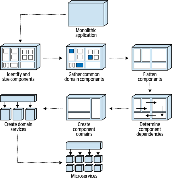
Figure 5-1. Component-based decomposition pattern flow and usage
Each pattern described in this chapter is divided into three sections. The first section, “Pattern Description,” describes how the pattern works, why the pattern is important, and what the outcome is of applying the pattern. Knowing that most systems are moving targets during a migration, the second section, “Fitness Functions for Governance,” describes the automated governance that can be used after applying the pattern to continually analyze and verify the correctness of the codebase during ongoing maintenance. The third section uses the real-world Sysops Squad application (see “Introducing the Sysops Squad Saga”) to illustrate the use of the pattern and illustrate the transformations of the application after the pattern has been applied.
Identify and Size Components Pattern
Pattern Description
Because services are built from components, it is critical to not only identify the components within an application, but to properly size them as well. This pattern is used to identify components that are either too big (doing too much) or too small (not doing enough). Components that are too large relative to other components are generally more coupled to other components, are harder to break into separate services, and lead to a less modular architecture.
Having a relatively consistent component size within an application is important. Generally speaking, the size of components in an application should fall between one to two standard deviations from the average (or mean) component size. In addition, the percentage of code represented by each component should be somewhat evenly distributed between application components and not vary significantly.
| Component name | Component namespace | Percent | Statements | Files |
|---|---|---|---|---|
Billing Payment |
| 5 | 4,312 | 23 |
Billing History |
| 4 | 3,209 | 17 |
Customer Notification |
| 2 | 1,433 | 7 |
- Component name
-
A descriptive name and identifier of the component that is
consistent throughout application diagrams and documentation. The component name should be clear enough to be as self-describing as possible. For example, the component Billing History shown inTable 5-1 is clearly a component that contains source code files used to manage a customer’s billing history. If the distinct role and responsibility of the component isn’t immediately identifiable, consider changing the component (and potentially the corresponding namespace) to a more descriptive one. For example, a component named Ticket Manager leaves too many unanswered questions about its role and responsibility in the system, and should be renamed to better describe its role. - Component namespace
-
The physical (or logical) identification of the component representing where the
source code files implementing that component are grouped and stored. This identifier is usually denoted through a namespace, package structure (Java), or directory structure. When a directory structure is used to denote the component, we usually convert the file separator to a dot (.) and create a corresponding logical namespace. For example, the component namespace for source code files in the ss/customer/notification directory structure would have the namespace valuess.customer.notification. Some languages require that the namespace match the directory structure (such as Java with a package), whereas other languages (such as C# with a namespace) do not enforce this constraint. Whatever namespace identifier is used, make sure the type of identifier is consistent across all of the components in the application. - Percent
- The relative size of the component based on its percentage of the overall source code containing that component. The percent metric is helpful in identifying components that appear too large or too small in the overall application. This metric is calculated by taking the total number of statements within the source code files representing that component and dividing that number by the total number of statements in the entire codebase of the application. For example, the percent value of 5 for theTable 5-1 means that this component constitutes 5% of the overall codebase.
ss.billing.paymentcomponent in - Statements
-
The sum of the total number of source code statements in all source files contained within that component. This metric is useful for determining not only the relative size of the components within an application, but also for determining the overall complexity of the component. For example, a seemingly simple single-purpose component named Customer Wishlist might have a total of 12,000 statements, indicating that the processing of wish list items is perhaps more complex than it looks. This metric is also necessary for calculating the percent metric previously described.
- Files
-
The total number of source code files (such as classes, interfaces, types, and so on) that are contained within the component. While this metric has little to do with the size of a component, it does provide additional information about the component from a class structure standpoint. For example, a component with 18,409 statements and only 2 files is a good candidate for refactoring into smaller, more contextual classes.
When resizing a large component, we recommend using a functional decomposition approach or a domain-driven approach to identify subdomains that might exist within the large component. For example, assume the Sysops Squad application has a Trouble Ticket component containing 22% of the codebase that is responsible for ticket creation, assignment, routing, and completion. In this case, it might make sense to break the single Trouble Ticket component into four separate components (Ticket Creation, Ticket Assignment, Ticket Routing, and Ticket Completion), reducing the percentage of code each component represents, therefore creating a more modular application. If no clear subdomains exist within a large component, then leave the component as is.
Fitness Functions for Governance
Once this decomposition pattern has been applied and components
Fitness functions can be implemented through custom-written code or through the use of open source or COTS tools as part of a CI/CD pipeline. Some of the automated fitness functions that can be used to help govern this decomposition pattern are as follows.
Fitness function: Maintain component inventory
Example 5-1. Pseudocode for maintaining component inventory
# Get prior component namespaces that are stored in a datastoreLISTprior_list=read_from_datastore()# Walk the directory structure, creating namespaces for each complete pathLISTcurrent_list=identify_components(root_directory)# Send an alert if new or removed components are identifiedLISTadded_list=find_added(current_list,prior_list)LISTremoved_list=find_removed(current_list,prior_list)IFadded_listNOTEMPTY{add_to_datastore(added_list)send_alert(added_list)}IFremoved_listNOTEMPTY{remove_from_datastore(removed_list)send_alert(removed_list)}
Fitness function: No component shall exceed <some percent> of the overall codebase
This automated holistic fitness function, usually triggered on deployment through a CI/CD pipeline, identifies components that exceed a given threshold in terms of the percentage of overall source code represented by that component, and alerts the architect if any component exceeds that threshold. As mentioned earlier in this chapter, the threshold percentage value will vary depending on the size of the application, but should be set so as to identify significant outliers. For example, for a relatively small application with only 10 components, setting the percentage threshold to something like 30% would sufficiently identify a component that is too large, whereas for a large application with 50 components, a threshold of 10% would be more appropriate. Example 5-2 shows the pseudocode and algorithm for one possible implementation of this fitness function.
Example 5-2. Pseudocode for maintaining component size based on percent of code
# Walk the directory structure, creating namespaces for each complete pathLISTcomponent_list=identify_components(root_directory)# Walk through all of the source code to accumulate total statementstotal_statements=accumulate_statements(root_directory)# Walk through the source code for each component, accumulating statements# and calculating the percentage of code each component represents. Send# an alert if greater than 10%FOREACHcomponentINcomponent_list{component_statements=accumulate_statements(component)percent=component_statements/total_statementsIFpercent>.10{send_alert(component,percent)}}
Fitness function: No component shall exceed <some number of standard deviations> from the mean component size
This automated holistic fitness function, usually triggered on deployment through a CI/CD pipeline, identifies components that exceed a given threshold in terms of the number of standard deviations from the mean of all component sizes (based on the total number of statements in the component), and alerts the architect if any component exceeds that threshold.
Standard deviation is a useful means of determining outliers in terms of component size.
where N is the number of observed values, is the observed values, and is the mean of the observed values. The mean of observed values () is calculated as follows:
Example 5-3. Pseudocode for maintaining component size based on number of standard deviations
# Walk the directory structure, creating namespaces for each complete pathLISTcomponent_list=identify_components(root_directory)# Walk through all of the source code to accumulate total statements and number# of statements per componentSETtotal_statementsTO0MAPcomponent_size_mapFOREACHcomponentINcomponent_list{num_statements=accumulate_statements(component)ADDnum_statementsTOtotal_statementsADDcomponent,num_statementsTOcomponent_size_map}# Calculate the standard deviationSETsquare_diff_sumTO0num_components=get_num_entries(component_list)mean=total_statements/num_componentsFOREACHcomponent,sizeINcomponent_size_map{diff=size-meanADDsquare(diff)TOsquare_diff_sum}std_dev=square_root(square_diff_sum/(num_components-1))# For each component calculate the number of standard deviations from the# mean. Send an alert if greater than 3FOREACHcomponent,sizeINcomponent_size_map{diff_from_mean=absolute_value(size-mean);num_std_devs=diff_from_mean/std_devIFnum_std_devs>3{send_alert(component,num_std_devs)}}
Sysops Squad Saga: Sizing Components
Tuesday, November 2, 09:12
| Component name | Component namespace | Percent | Statements | Files |
|---|---|---|---|---|
Login |
| 2 | 1865 | 3 |
Billing Payment |
| 5 | 4,312 | 23 |
Billing History |
| 4 | 3,209 | 17 |
Customer Notification |
| 2 | 1,433 | 7 |
Customer Profile |
| 5 | 4,012 | 16 |
Expert Profile |
| 6 | 5,099 | 32 |
KB Maint |
| 2 | 1,701 | 14 |
KB Search |
| 3 | 2,871 | 4 |
Reporting |
| 33 | 27,765 | 162 |
Ticket |
| 8 | 7,009 | 45 |
Ticket Assign |
| 9 | 7,845 | 14 |
Ticket Notify |
| 2 | 1,765 | 3 |
Ticket Route |
| 2 | 1,468 | 4 |
Support Contract |
| 5 | 4,104 | 24 |
Survey |
| 3 | 2,204 | 5 |
Survey Notify |
| 2 | 1,299 | 3 |
Survey Templates |
| 2 | 1,672 | 7 |
User Maintenance |
| 4 | 3,298 | 12 |
Addison noticed that most of the components listed in Table 5-2 are about the same size, with the exception of the Reporting component (ss.reporting) which consisted of 33% of the codebase. Since the Reporting component was significantly larger than the other components (illustrated in Figure 5-2), Addison chose to break this component apart to reduce its overall size.
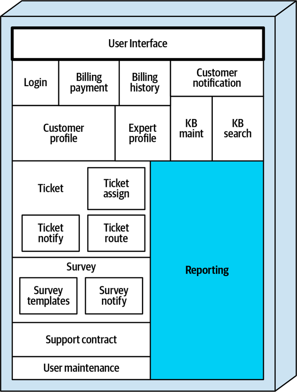
Figure 5-2. The Reporting component is too big and should be broken apart
After doing some analysis, Addison found that the reporting component contained source code that implemented three categories of reports:
-
Ticketing reports (ticket demographics reports, tickets per day/week/month reports, ticket resolution time reports, and so on)
-
Expert reports (expert utilization reports, expert distribution reports, and so on)
-
Financial reports (repair cost reports, expert cost reports, profit reports, and so on)
Addison also identified common (shared) code that all reporting categories used, such as common utilities, calculators, shared data queries, report distribution, and shared data formatters. Addison created an architecture story (see “Architecture Stories”) for this refactoring and explained it to the development team. Sydney, one of the Sysops Squad developers assigned the architecture story, refactored the code to break apart the single Reporting component into four separate components—a Reporting Shared component containing the common code and three other components (Ticket Reports, Expert Reports, and Financial Reports), each representing a functional reporting area, as illustrated in Figure 5-3.
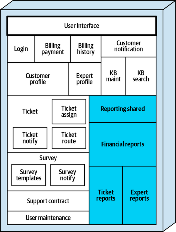
Figure 5-3. The large Reporting component broken into smaller reporting components
After Sydney committed the changes, Addison reanalyzed the code and verified that all of the components were now fairly equally distributed in size. Addison recorded the results of applying this decomposition pattern in Table 5-3.
| Component name | Component namespace | Percent | Statements | Files |
|---|---|---|---|---|
Login |
| 2 | 1865 | 3 |
Billing Payment |
| 5 | 4,312 | 23 |
Billing History |
| 4 | 3,209 | 17 |
Customer Notification |
| 2 | 1,433 | 7 |
Customer Profile |
| 5 | 4,012 | 16 |
Expert Profile |
| 6 | 5,099 | 32 |
KB Maint |
| 2 | 1,701 | 14 |
KB Search |
| 3 | 2,871 | 4 |
Reporting Shared |
| 7 | 5,309 | 20 |
Ticket Reports |
| 8 | 6,955 | 58 |
Expert Reports |
| 9 | 7,734 | 48 |
Financial Reports |
| 9 | 7,767 | 36 |
Ticket |
| 8 | 7,009 | 45 |
Ticket Assign |
| 9 | 7,845 | 14 |
Ticket Notify |
| 2 | 1,765 | 3 |
Ticket Route |
| 2 | 1,468 | 4 |
Support Contract |
| 5 | 4,104 | 24 |
Survey |
| 3 | 2,204 | 5 |
Survey Notify |
| 2 | 1,299 | 3 |
Survey Templates |
| 2 | 1,672 | 7 |
User Maintenance |
| 4 | 3,298 | 12 |
Notice in the preceding Sysops Squad Saga that Reporting no longer exists as a component in Table 5-3 or Figure 5-3. Although the namespace still exists (ss.reporting), it is no longer considered a component, but rather a subdomain.
Gather Common Domain Components Pattern
Pattern Description
Consolidating common domain functionality helps eliminate duplicate services when breaking apart a monolithic system. Often there are only very subtle differences among common domain functionality that is duplicated throughout the application, and these differences can be easily resolved within a single common service (or shared library).
Another way of identifying common domain functionality is through the name of a logical component or its corresponding namespace. Consider the following components (represented as namespaces) in a large codebase:
-
Ticket Auditing (
penultimate.ss.ticket.audit) -
Billing Auditing (
penultimate.ss.billing.audit) -
Survey Auditing (
penultimate.ss.survey.audit)
Notice how each of these components (Ticket Auditing, Billing Auditing, and Survey Auditing) all have the same thing in common—writing the action performed and the user requesting the action to an audit table. While the context may be different, the final outcome is the same—inserting a row in an audit table. This common domain functionality can be consolidated into a new component called penultimate.ss.shared.audit, resulting in less duplication of code and also fewer services in the resulting distributed architecture.
Not all common domain functionality necessarily becomes a shared service. Alternatively, common code could be gathered into a shared library that is bound to the code during compile time. The pros and cons of using a shared service rather than a shared library are discussed in detail in Chapter 8.
Fitness Functions for Governance
Automating the governance of shared domain functionality
Fitness function: Find common names in leaf nodes of component namespace
.calculate or .validate). Example 5-4. Pseudocode for finding common namespace leaf node names
# Walk the directory structure, creating namespaces for each complete pathLISTcomponent_list=identify_components(root_directory)# Locate possible duplicate component node names that are not in the exclusion# list stored in a datastoreLISTexcluded_leaf_node_list=read_datastore()LISTleaf_node_listLISTcommon_component_listFOREACHcomponentINcomponent_list{leaf_name=get_last_node(component)IFleaf_nameINleaf_node_listANDleaf_nameNOTINexcluded_leaf_node_list{ADDcomponentTOcommon_component_list}ELSE{ADDleaf_nameTOleaf_node_list}}# Send an alert if any possible common components were foundIFcommon_component_listNOTEMPTY{send_alert(common_component_list)}
Fitness function: Find common code across components
This automated holistic fitness function can be triggered on deployment through a CI/CD pipeline to locate common classes used between namespaces. While not always accurate, it does help in alerting an architect of possible duplicate domain functionality. Like the previous fitness function, an exclusion file is used to reduce the number of “false positives” for known common code that is not considered duplicate domain logic. Example 5-5 shows the pseudocode for thisfitness function.
Example 5-5. Pseudocode for finding common source files between components
# Walk the directory structure, creating namespaces for each complete path and a list# of source file names for each componentLISTcomponent_list=identify_components(root_directory)LISTsource_file_list=get_source_files(root_directory)MAPcomponent_source_file_mapFOREACHcomponentINcomponent_list{LISTcomponent_source_file_list=get_source_files(component)ADDcomponent,component_source_file_listTOcomponent_source_file_map}# Locate possible common source file usage across components that are not in# the exclusion list stored in a datastoreLISTexcluded_source_file_list=read_datastore()LISTcommon_source_file_listFOREACHsource_fileINsource_file_list{SETcountTO0FOREACHcomponent,component_source_file_listINcomponent_source_file_map{IFsource_fileINcomponent_source_file_list{ADD1TOcount}}IFcount>1ANDsource_fileNOTINexcluded_source_file_list{ADDsource_fileTOcommon_source_file_list}}# Send an alert if any source files are used in multiple componentsIFcommon_source_file_listNOTEMPTY{send_alert(common_source_file_list)}
Sysops Squad Saga: Gathering Common Components
Friday, November 5, 10:34
| Component | Namespace | Responsibility |
|---|---|---|
Customer Notification |
| General notification |
Ticket Notify |
| Notify that expert is en route |
Survey Notify |
| Send survey email |
While each of these notification components had a different context for notifying a customer, Addison realized they all have one thing in common—they all sent information to a customer. Figure 5-4 illustrates these common notification components within the Sysops Squad application.
Noticing that the source code contained in these components was also very similar, Addison consulted with Austen (the other Sysops Squad architect). Austen liked the idea of a single notification component, but was concerned about impacting the overall level of coupling between components. Addison agreed that this might be an issue and investigated this trade-off further.
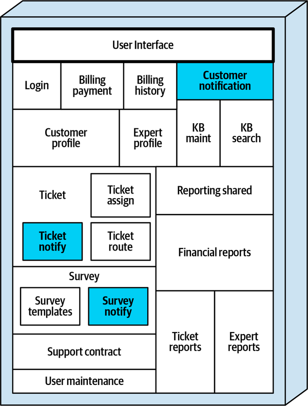
Figure 5-4. Notification functionality is duplicated throughout the application
Addison analyzed the incoming (afferent) coupling level for the existing Sysops Squad notification components and came up with the resulting coupling metrics listed in Table 5-5, with “CA” representing the number of other components requiring that component (afferent coupling).
| Component | CA | Used by |
|---|---|---|
Customer Notification | 2 | Billing Payment, Support Contract |
Ticket Notify | 2 | Ticket, Ticket Route |
Survey Notify | 1 | Survey |
Addison then found that if the customer notification functionality was consolidated into a single component, the coupling level for the resulting single component increased to an incoming coupling level of 5, as shown in Table 5-6.
| Component | CA | Used by |
|---|---|---|
Notification | 5 | Billing Payment, Support Contract, Ticket, Ticket Route, Survey |
Addison brought these findings to Austen, and they discussed the results. What they found is that, while the new consolidated component had a fairly high level of incoming coupling, it didn’t affect the overall afferent (incoming) coupling level for notifying a customer. In other words, the three separate components had a total incoming coupling level of 5, but so did the single consolidated component.
Addison and Austen both realized how important it was to
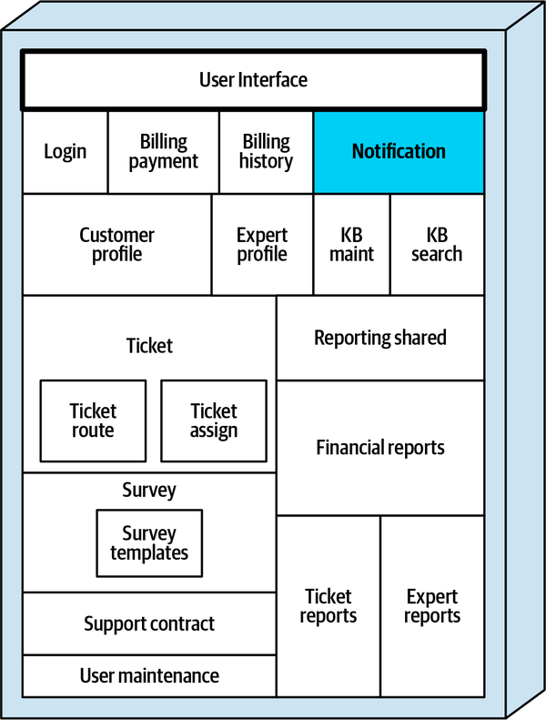
Figure 5-5. Notification functionality is consolidated into a new single component called Notification
Table 5-7 shows the resulting components after Sydney implemented the architecture story Addison created. Notice that the Customer Notification component (ss.customer.notification), Ticket Notify component (ss.ticket.notify), and Survey Notify components (ss.survey.notify) were removed, and the source code moved to the new consolidated Notification component ( ss.notification).
| Component | Namespace | Responsibility |
|---|---|---|
Login |
| User and customer login |
Billing Payment |
| Customer monthly billing |
Billing History |
| Payment history |
Customer Profile |
| Maintain customer profile |
Expert Profile |
| Maintain expert profile |
KB Maint |
| Maintain & view knowledge base |
KB Search |
| Search knowledge base |
Notification |
| All customer notification |
Reporting Shared |
| Shared functionality |
Ticket Reports |
| Create ticketing reports |
Expert Reports |
| Create expert reports |
Financial Reports |
| Create financial reports |
Ticket |
| Ticket creation & maintenance |
Ticket Assign |
| Assign expert to ticket |
Ticket Route |
| Send ticket to expert |
Support Contract |
| Support contract maintenance |
Survey |
| Send and receive surveys |
Survey Templates |
| Maintain survey templates |
User Maintenance |
| Maintain internal users |
Flatten Components Pattern
As mentioned previously, components—the building blocks
Pattern Description
ss.survey) and Survey Templates (ss.survey.templates). Notice in ss.survey namespace, which contains five class files used to manage and collect the surveys, is extended with the ss.survey.templates namespace to include seven classes representing each survey type send out to customers. | Component name | Component namespace | Files |
|---|---|---|
→ Survey |
| 5 |
Survey Templates |
| 7 |
While this structure might seem to make sense from a developer’s standpoint in order to keep the template code separate from survey processing, it does create some problems because Survey Templates, as a component, would be considered part of the Survey component. One might be tempted to consider Survey Templates as a subcomponent of Survey, but then issues arise when trying to form services from these components—should both components reside in a single service called Survey, or should the Survey Templates be a separate service from the Survey service?
We’ve resolved this dilemma by defining a component as the last node (or leaf node) of the namespace or directory structure. With this definition, ss.survey.templates is a component, whereas ss.survey would be considered a subdomain, not a component. We further define namespaces such as ss.survey as root namespaces because they are extended with other namespace nodes (in this case, .templates).
Notice how the ss.survey root namespace in Table 5-8 contains five class files. We call these class files orphaned classes because they do not belong to any definable component. Recall that a component is identified by a leaf node namespace containing source code. Because the ss.survey namespace was extended to include .templates, ss.survey is no longer considered a component and therefore should not contain any class files.
The following terms and corresponding definitions are important for understanding and applying the Flatten Components decomposition pattern:
- Component
-
A collection of classes grouped
within a leaf node namespace that performs some sort of specific functionality in the application (such as payment processing or customer survey functionality). - Root namespace
- A namespace node that has been extended by anothernamespace node. For example, given the namespaces
ss.surveyandss.survey.templates,ss.surveywould be considered a root namespace because it is extended by.templates. Root namespaces are also sometimes referred to as subdomains. - Orphaned classes
- Classes contained within a root namespace, and hence have no definable component associated with them.
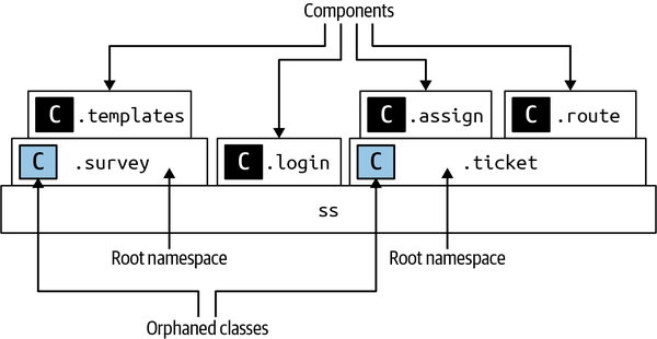
Figure 5-6. Components, root namespaces, and orphaned classes (C box denotes source code)
Notice that since both ss.survey and ss.ticket are extended through other namespace nodes, those namespaces are considered root namespaces, and the classes contained in those root namespaces are hence orphaned classes (belonging to no defined component). Thus, the only components denoted in Figure 5-6 are ss.survey.templates, ss.login, ss.ticket.assign, and ss.ticket.route.
The Flatten Components decomposition pattern is used to move orphaned classes to create well-defined components that exist only as leaf nodes of a directory or namespace, creating well-defined subdomains (root namespaces) in the process. We refer to the flattening of components as the breaking down (or building up) of namespaces within an application to remove orphaned classes. For example, one way of flattening the ss.survey root namespace in Figure 5-6 and remove orphaned classes is to move the source code contained in the ss.survey.templates namespace down to the ss.survey namespace, thereby making ss.survey a single component (.survey is now the leaf node of that namespace). This flattening option is illustrated in Figure 5-7.
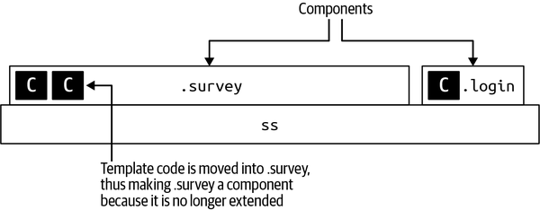
Figure 5-7. Survey is flattened by moving the survey template code into the .survey namespace
Alternatively, flattening could also be applied by taking the source code in ss.survey and applying functional decomposition or domain-driven design to identify separate functional areas within the root namespace, thus forming components from those functional areas. For example, suppose the functionality within the ss.survey namespace creates and sends a survey to a customer, and then processes a completed survey received from the customer. Two components could be created from the ss.survey namespace: ss.survey.create, which creates and sends the survey, and ss.survey.process, which processes a survey received from a customer. This form of flattening is illustrated in Figure 5-8.
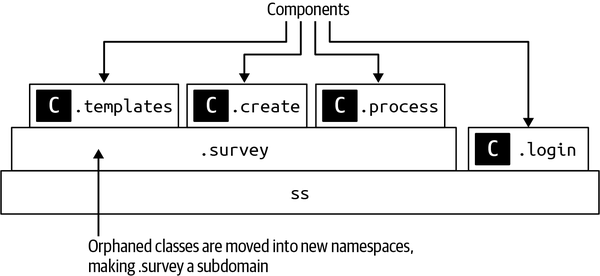
Figure 5-8. Survey is flattened by moving the orphaned classes to new leaf nodes ( components)
Tip
Regardless of the direction of flattening, make sure source code files reside only in leaf node namespaces or directories so that source code can always be identified within a specific component.
Another common scenario where orphaned source code might reside in a root namespace is when code is shared by other components within that namespace. Consider the example in Figure 5-9 where customer survey functionality resides in three components (ss.survey.templates, ss.survey.create, and ss.survey.process), but common code (such as interfaces, abstract classes, common utilities) resides in the root namespace ss.survey.
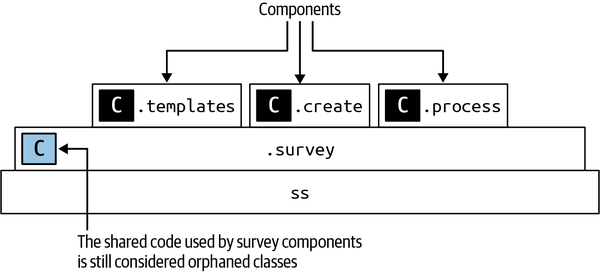
Figure 5-9. Shared code in .survey is considered orphaned classes and should be moved
The shared classes in ss.survey would still be considered orphaned classes, even though they represent shared code. Applying the Flatten Components pattern would move those shared orphaned classes to a new component called ss.survey.shared, therefore removing all orphaned classes from the ss.survey subdomain, as illustrated in Figure 5-10.
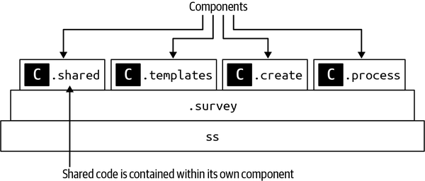
Figure 5-10. Shared survey code is moved into its own component
Our advice when moving shared code to a separate component (leaf node namespace)
.sharedcode, .commoncode, or some such unique name. This allows the architect to generate metrics based on the number of shared components in the codebase, as well as the percentage of source code that is shared in the application. This is a good indicator as to the feasibility of breaking up the monolithic application. For example, if the sum of all the statements in all namespaces ending with .sharedcode constitutes 45% of the overall source code, chances are moving to a distributed architecture will result in too many shared libraries and end up becoming a nightmare to maintain because of shared library dependencies.Another good metric involving the analysis of shared code is the number of components ending in .sharedcode (or whatever common shared namespace node is used). This metric gives the architect insight into how many shared libraries (JAR, DLL, and so on) or shared services will result from breaking up the monolithic application.
Fitness Functions for Governance
Fitness function: No source code should reside in a root namespace
Example 5-6. Pseudocode for finding code in root namespaces
# Walk the directory structure, creating namespaces for each complete pathLISTcomponent_list=identify_components(root_directory)# Send an alert if a non-leaf node in any component contains source filesFOREACHcomponentINcomponent_list{LISTcomponent_node_list=get_nodes(component)FOREACHnodeINcomponent_node_list{IFcontains_code(node)ANDNOTlast_node(component_node_list){send_alert(component)}}}
Sysops Squad Saga: Flattening Components
Wednesday, November 10, 11:10

Figure 5-11. The Survey and Ticket components contain orphaned classes and should be flattened
| Component name | Component namespace | Statements | Files |
|---|---|---|---|
Ticket |
| 7,009 | 45 |
Ticket Assign |
| 7,845 | 14 |
Ticket Route |
| 1,468 | 4 |
Survey |
| 2,204 | 5 |
Survey Templates |
| 1,672 | 7 |
Addison decided to address the ticketing components first. Knowing that flattening components meant getting rid of source code in nonleaf nodes, Addison had two choices: consolidate the code contained in the ticket assignment and ticket routing components into the ss.ticket component, or break up the 45 classes in the ss.ticket component into separate components, thus making ss.ticket a subdomain. Addison discussed these options with Sydney (one of the Sysops Squad developers), and based on the complexity and frequent changes in the ticket assignment functionality, decided to keep those components separate and move the orphaned code from the ss.ticket root namespace into other namespaces, thus forming new components.
With help from Sydney, Addison found that the 45 orphaned classes contained in the ss.ticket namespace implemented the following ticketing functionality:
-
Ticket creation and maintenance (creating a ticket, updating a ticket, canceling a ticket, etc.)
-
Ticket completion logic
-
Shared code common to most of the ticketing functionality
Since ticket assignment and ticket routing functionality were already in their own components (ss.ticket.assign and ss.ticket.route, respectively), Addison created an architecture story to move the source code contained in the ss.ticket namespace to three new components, as shown in Table 5-10.
| Component | Namespace | Responsibility |
|---|---|---|
Ticket Shared |
| Common code and utilities |
Ticket Maintenance |
| Add and maintain tickets |
Ticket Completion |
| Complete ticket and initiate survey |
Ticket Assign |
| Assign expert to ticket |
Ticket Route |
| Send ticket to expert |
Addison then considered the survey functionality. Working with Sydney, Addison found that the survey functionality rarely changed and was not overly complicated. Sydney talked with Skyler, the Sysops Squad developer who originally created the ss.survey.templates namespace, and found there was no compelling reason to separate the survey templates into their own namespace (“It just seemed like a good idea at the time,” said Skyler). With this information, Addison created an architecture story to move the seven class files from ss.survey.templates into the ss.survey namespace and removed the ss.survey.template component, as shown in Table 5-11.
| Component | Namespace | Responsibility |
|---|---|---|
Survey |
| Send and seceive surveys |
After applying the Flatten Components pattern (illustrated in Figure 5-12), Addison observed that there were no “hills” (component upon component) or orphaned classes and that all of the components were contained only in the leaf nodes of the corresponding namespace.
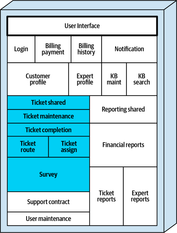
Figure 5-12. The Survey component was flattened into a single component, whereas the Ticket component was raised up and flattened, creating a Ticket subdomain
Addison recorded the results of the refactoring efforts thus far in applying these decomposition patterns and listed them in Table 5-12.
| Component | Namespace |
|---|---|
Login |
|
Billing Payment |
|
Billing History |
|
Customer Profile |
|
Expert Profile |
|
KB Maint |
|
KB Search |
|
Notification |
|
Reporting Shared |
|
Ticket Reports |
|
Expert Reports |
|
Financial Reports |
|
Ticket Shared |
|
Ticket Maintenance |
|
Ticket Completion |
|
Ticket Assign |
|
Ticket Route |
|
Support Contract |
|
Survey |
|
User Maintenance |
|
Determine Component Dependencies Pattern
-
Is it feasible to break apart the existing monolithic application?
-
What is the rough overall level of effort for this migration?
-
Is this going to require a rewrite of the code or a refactoring of the code?
One of your authors was engaged several years ago in a large migration effort to move a complex monolithic application to microservices. On the first day of the project, the CIO wanted to know only one thing—was this migration effort a golfball, basketball, or an airliner? Your author was curious about the sizing comparisons, but the CIO insisted that the answer to this simple question shouldn’t be that difficult given that kind of coarse-grained sizing. As it turned out, applying the Determine Component Dependencies pattern quickly and easily answered this question for the CIO—the effort was unfortunately an airliner, but only a small Embraer 190 migration rather than a large Boeing 787 Dreamliner migration.
Pattern Description
It’s important to note that this pattern is about component dependencies, not individual class dependencies within a component. A component dependency is formed when a class from one component (namespace) interacts with a class from another component (namespace). For example, suppose the CustomerSurvey class in the ss.survey component invokes a method in the CustomerNotification class in the ss.notification component to send out the customer survey, as illustrated in the pseudocode in Example 5-7.
Example 5-7. Pseudocode showing a dependency between the Survey and Notification components
namespacess.surveyclassCustomerSurvey{functioncreateSurvey{...}functionsendSurvey{...ss.notification.CustomerNotification.send(customer_id,survey)}}
Notice the dependency between the Survey and Notification components, because the CustomerNotification class used by the CustomerSurvey class resides outside the ss.survey namespace. Specifically, the Survey component would have an efferent (or outgoing) dependency on the Notification component, and the Notification component would have an afferent (or incoming) dependency on the Survey component.
Note that the classes within a particular component may be a highly coupled mess of numerous dependencies, but that doesn’t matter when applying this pattern—what matters is only those dependencies between components.
Several tools are
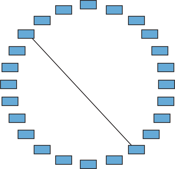
Figure 5-13. A monolithic application with minimal component dependencies takes less effort to break apart (golf ball sizing)
With a dependency diagram like Figure 5-13, the answers to the three key questions are as follows:
-
Is it feasible to break apart the existing monolithic application? Yes
-
What is the rough overall level of effort for this migration? A golf ball (relatively straightforward)
-
Is this going to be a rewrite of the code or a refactoring of the code? Refactoring (moving existing code into separately deployed services)
Now look at the dependency diagram shown in Figure 5-14. Unfortunately, this diagram is typical of the dependencies between components in most business applications. Notice in particular how the lefthand side of this diagram has the highest level of coupling, whereas the righthand side looks much more feasible to break apart.
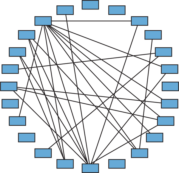
Figure 5-14. A monolithic application with a high number of component dependencies takes more effort to break apart (basketball sizing)
With this level of tight coupling between components, the answers to the three key questions are not very encouraging:
-
Is it feasible to break apart the existing monolithic application? Maybe…
-
What is the rough overall level of effort for this migration? A basketball (much harder)
-
Is this going to be a rewrite of the code or a refactoring of the code? Likely a combination of some refactoring and some rewriting of the existing code
Finally, consider the dependency diagram illustrated in Figure 5-15. In this case, the architect should turn around and run in the opposite direction as fast as they can!
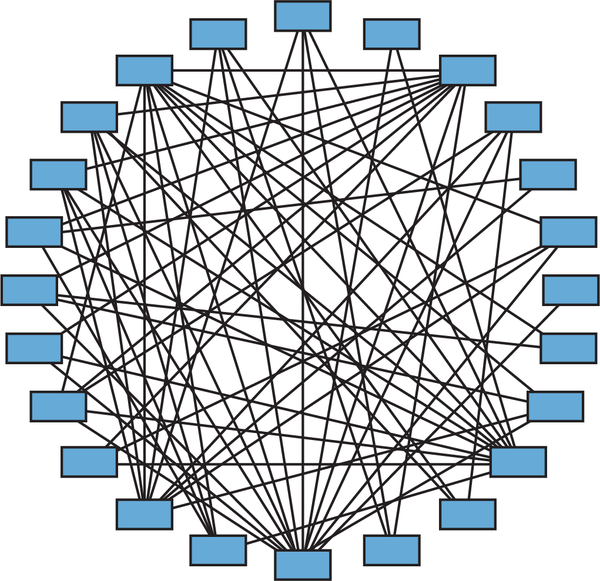
Figure 5-15. A monolithic application with too many component dependencies is not feasible to break apart (airliner sizing)
The answers to the three key questions for applications with this sort of component dependency matrix are not surprising:
-
Is it feasible to break apart the existing monolithic application? No
-
What is the rough overall level of effort for this migration? An airliner
-
Is this going to be a rewrite of the code or a refactoring of the code? Total rewrite of the application
We cannot stress enough the importance of these kinds of
It has been our experience that component coupling is one of the most significant factors in determining the overall success (and feasibility) of a monolithic migration effort. Identifying and understanding the level of component coupling not only allows the architect to determine the feasibility of the migration effort, but also what to expect in terms of the overall level of effort. Unfortunately, all too often we see teams jump straight into breaking a monolithic application into microservices without having any analysis or visuals into what the monolithic application even looks like. And not surprisingly, those teams struggle to break apart their monolithic applications.
This pattern is useful not only for identifying the overall level of component coupling in an application, but also for determining dependency refactoring opportunities prior to breaking apart the application. When analyzing the coupling level between components, it is important to analyze both afferent (incoming) coupling (denoted in most tools as CA), and efferent (outgoing) coupling (denoted in most tools as CE). CT, or total coupling, is the sum of both afferent and efferent coupling.
Many times, breaking apart a component can reduce the level of coupling of that component. For example, assume component A has an afferent coupling level of 20 (meaning, 20 other components are dependent on the functionality of the component). This does not necessarily mean that all 20 of the other components require all of the functionality from component A. Maybe 14 of the other components require only a small part of the functionality contained in component A. Breaking component A into two different components (component A1 containing the smaller, coupled functionality, and component A2 containing the majority of the functionality) reduces the afferent coupling in component A2 to 6, with component A1 having an afferent coupling level of 14.
Fitness Functions for Governance
Fitness function: No component shall have more than <some number> of total dependencies
Example 5-8. Pseudocode for limiting the total number of dependencies of any given component
# Walk the directory structure, gathering components and the source code files# contained within those componentsLISTcomponent_list=identify_components(root_directory)MAPcomponent_source_file_mapFOREACHcomponentINcomponent_list{LISTcomponent_source_file_list=get_source_files(component)ADDcomponent,component_source_file_listTOcomponent_source_file_map}# Determine how many references exist for each source file and send an alert if# the total dependency count is greater than 15FOREACHcomponent,component_source_file_listINcomponent_source_file_map{FOREACHsource_fileINcomponent_source_file_list{incomingcount=used_by_other_components(source_file,component_source_file_map){outgoing_count=uses_other_components(source_file){total_count=incomingcount+outgoingcount}IFtotal_count>15{send_alert(component,total_count)}}
Fitness function: <some component> should not have a dependency on <another component>
This automated holistic fitness function can be triggered on deployment through a CI/CD pipeline to restrict certain components from having a dependency on other ones. In most cases, there will be one fitness function for each dependency restriction so that, if there were 10 different component restrictions, there would be 10 different fitness functions, one for each component in question. Example 5-9 shows an example using ArchUnit for ensuring that the Ticket Maintenance component (ss.ticket.maintenance) does not have a dependency on the Expert Profile component (ss.expert.profile).
Example 5-9. ArchUnit code for governing dependency restrictions between components
publicvoidticket_maintenance_cannot_access_expert_profile(){noClasses().that().resideInAPackage("..ss.ticket.maintenance..").should().accessClassesThat().resideInAPackage("..ss.expert.profile..").check(myClasses);}
Sysops Squad Saga: Identifying Component Dependencies
Monday, November 15, 09:45
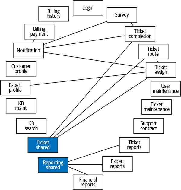
Figure 5-16. Component dependencies in the Sysops Squad application
However, after further analysis, Addison saw that the Notification component had the most dependencies, which was not surprising given that it’s a shared component. However, Addison also saw lots of dependencies within the Ticketing and Reporting components. Both of these domain areas have a specific component for shared code (interfaces, helper classes, entity classes, and so on). Realizing that both the ticketing and reporting shared code contains mostly compile-based class references and would likely be implemented as shared libraries rather than services, Addison filtered out these components to get a better view of the dependencies between the core functionality of the application, which is illustrated in Figure 5-17.
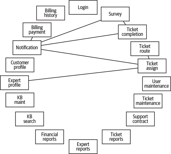
Figure 5-17. Component dependencies in the Sysops Squad application without shared library dependencies
With the shared components filtered out, Addison saw that the dependencies were fairly minimal. Addison showed these results to Austen, and they both agreed that most of the components were relatively self-contained and it appeared that the Sysops Squad application was a good candidate for breaking apart into a distributed architecture.
Create Component Domains Pattern
Pattern Description
When breaking apart monolithic applications, consider first moving to service-based architecture as a stepping-stone to other distributed architectures.
Creating component domains is an effective way of determining what will eventually become domain services in a service-based architecture.
.customer) refers to the domain, the third node represents a subdomain under the customer domain (.billing), and the leaf node (.payment) refers to the component. The .MonthlyBilling at the end of this namespace refers to a class file contained within the Payment component. 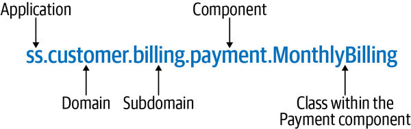
Figure 5-18. Component domains are identified through the namespace nodes
Since many older monolithic applications were implemented prior to the widespread
| Component | Namespace |
|---|---|
Billing Payment |
|
Billing History |
|
Customer Profile |
|
Support Contract |
|
Notice how each component is related to customer functionality, but the corresponding namespaces don’t reflect that association. To properly identify the Customer domain (manifested through the namespace ss.customer), the namespaces for the Billing Payment, Billing History, and Support Contract components would have to be modified to add the .customer node at the beginning of the namespace, as shown in Table 5-14.
| Component | Namespace |
|---|---|
Billing Payment |
|
Billing History |
|
Customer Profile |
|
Support Contract |
|
Notice in the prior table that all of the customer-related functionality (billing, profile maintenance, and support contract maintenance) is now grouped under .customer, aligning each component with that particular domain.
Fitness Functions for Governance
Once refactored, it’s important to govern the component domains to ensure
Fitness function: All namespaces under <root namespace node> should be restricted to <list of domains>
Example 5-10. ArchUnit code for governing domains within an application
publicvoidrestrict_domains(){classes().should().resideInAPackage("..ss.ticket..").orShould().resideInAPackage("..ss.customer..").orShould().resideInAPackage("..ss.admin..").check(myClasses);}
Sysops Squad Saga: Creating Component Domains
Thursday, November 18, 13:15
ss.ticket) containing all ticket-related functionality, including ticket processing, customer surveys, and knowledge base (KB) functionality; a Reporting domain (ss.reporting) containing all reporting functionality; a Customer domain (ss.customer) containing customer profile, billing, and support contracts; an Admin domain (ss.admin) containing maintenance of users and Sysops Squad experts; and finally, a Shared domain (ss.shared) containing login and notification functionality used by the other domains.The exercise Addison did in diagramming and grouping the
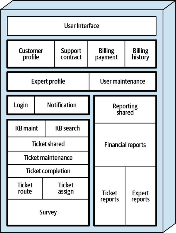
Figure 5-19. The five domains identified (with darkened borders) within the Sysops Squad application
Addison started with the Ticket domain and saw that while the core ticket functionality started with the namespace ss.ticket, the survey and knowledge base components did not. Therefore, Addison wrote an architecture story to refactor the components listed in Table 5-15 to align with the ticketing domain.
| Component | Domain | Current namespace | Target namespace |
|---|---|---|---|
KB Maint | Ticket |
|
|
KB Search | Ticket |
|
|
Ticket Shared | Ticket |
| Same (no change) |
Ticket Maintenance | Ticket |
| Same (no change) |
Ticket Completion | Ticket |
| Same (no change) |
Ticket Assign | Ticket |
| Same (no change) |
Ticket Route | Ticket |
| Same (no change) |
Survey | Ticket |
|
|
Next Addison considered the customer-related components, and found that the billing and survey components needed to be refactored to include them under the Customer domain, creating a Billing subdomain in the process. Addison wrote an architecture story for the refactoring of the Customer domain functionality, shown in Table 5-16.
| Component | Domain | Current namespace | Target namespace |
|---|---|---|---|
Billing Payment | Customer |
|
|
Billing History | Customer |
|
|
Customer Profile | Customer |
| Same (no change) |
Support Contract | Customer |
|
|
By applying the “Identify and Size Components Pattern”, Addison found that the reporting domain was already aligned, and no further action was needed with the reporting components listed in Table 5-17.
| Component | Domain | Current namespace | Target namespace |
|---|---|---|---|
Reporting Shared | Reporting |
| Same (no change) |
Ticket Reports | Reporting |
| Same (no change) |
Expert Reports | Reporting |
| Same (no change) |
Financial Reports | Reporting |
| Same (no change) |
Addison saw that both the Admin and Shared domains needed alignment as well, and decided to create a single architecture story for this refactoring effort and listed these components in Table 5-18. Addison also decided to rename the ss.expert.profile namespace to ss.experts to avoid an unnecessary Expert subdomain under the Admin domain.
| Component | Domain | Current namespace | Target namespace |
|---|---|---|---|
Login | Shared |
|
|
Notification | Shared |
|
|
Expert Profile | Admin |
|
|
User Maintenance | Admin |
|
|
With this pattern complete, Addison realized they were now prepared to structurally break apart the monolithic application and move to the first stage of a distributed architecture by applying the Create Domain Services pattern (described in the next section).
Create Domain Services Pattern
Pattern Description
In its simplest form, service-based architecture consists of a
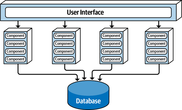
Figure 5-20. The basic topology for a service-based architecture
In addition to the benefits mentioned in “Component-Based Decomposition”, moving to service-based architecture
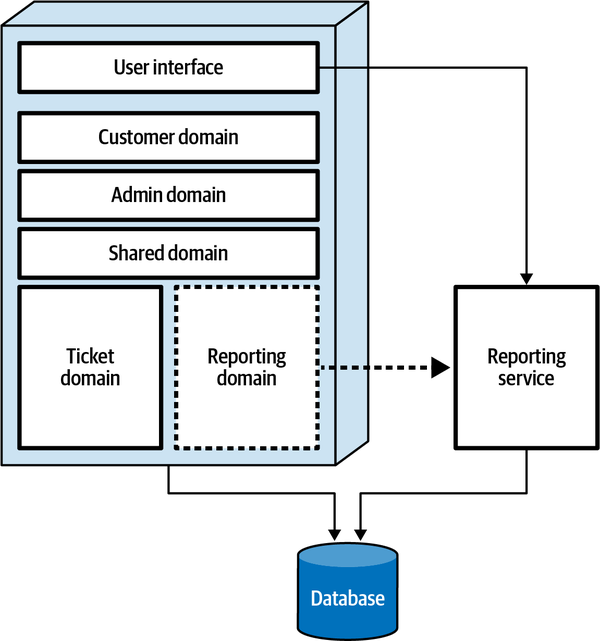
Figure 5-21. Component domains are moved to external domain services
A word of advice, however: don’t apply this pattern until all of the component domains have been identified and refactored. This helps reduce the amount of modification needed to each domain service when moving components (and hence source code) around. For example, suppose all of the ticketing and knowledge base functionality in the Sysops Squad application was grouped and refactored into a Ticket domain, and a new Ticket service created from that domain. Now suppose that the customer survey component (identified through the ss.customer.survey namespace) was deemed part of the Ticket domain. Since the Ticket domain had already been migrated, the Ticket service would now have to be modified to include the Survey component. Better to align and refactor all of the components into component domains first, then start migrating those component domains to domain services.
Fitness Functions for Governance
It is important to keep the components within each domain service aligned with the domain,
Fitness function: All components in <some domain service> should start with the same namespace
ss.ticket. Example 5-11. ArchUnit code for governing components within the Ticket domain service
publicvoidrestrict_domain_within_ticket_service(){classes().should().resideInAPackage("..ss.ticket..").check(myClasses);}
Sysops Squad Saga: Creating Domain Services
Tuesday, November 23, 09:04
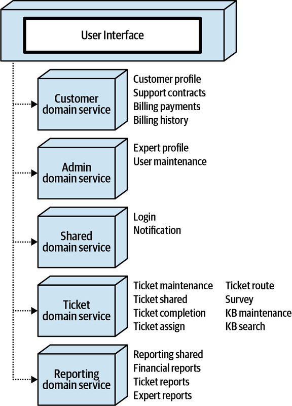
Figure 5-22. Separately deployed domain services result in a distributed Sysops Squad application
Summary
It has been our experience that “seat-of-the-pants” migration efforts rarely produce positive results. Applying these component-based decomposition patterns provides a structured, controlled, and incremental approach for breaking apart monolithic architectures. Once these patterns are applied, teams can now work to decompose monolithic data (see Chapter 6) and begin breaking apart domain services into more fine-grained microservices (see Chapter 7) as needed.
Chapter 6. Pulling Apart Operational Data
Thursday, October 7, 08:55
Now that the Sysops Squad application was successfully broken into separately deployed domain services,
“I’d like your opinions on how we might go about breaking up the Sysops Squad database,” said Addison.
“Wait a minute,” said Dana. “Who said anything about breaking apart the database?”
“Addison and I agreed last week that we needed to break up the Sysops Squad database,” said Devon. “As you know, the Sysops Squad application has been going through a major overhaul, and breaking apart the data is part of that overhaul.”
“I think the monolithic database is just fine,” said Dana. “I see no reason why it should be broken apart. Unless you can convince me otherwise, I’m not going to budge on this issue. Besides, do you know how hard it would be to break apart that database?”
“Of course it will be difficult,” said Devon, “but I know of a five-step process leveraging what are known as data domains that would work really well on this database. That way, we can even start investigating using different kinds of databases for certain parts of the application, like the knowledge base and even the customer survey functionality.”
“Let’s not get ahead of ourselves,” said Dana. “And let’s also not forget that I am the one who is responsible for all of these databases.”
Addison quickly realized things were spiraling out of control, and quickly put some key negotiation and facilitation skills to use. “OK,” said Addison, “we should have included you in our initial discussions, and for that I apologize. I should have known better. What can we do to bring you on board and help us decompose the Sysops Squad database?”
“That’s easy,” said Dana. “Convince me that the Sysops Squad database really does need to be broken apart. Provide me with a solid justification. If you can do that, then we’ll talk about Devon’s five-step process. Otherwise, it stays as it is.”
Interestingly enough, some of the same techniques used to break apart application functionality can be applied to breaking apart data as well. For example, components translate to data domains, class files translate to database tables, and coupling points between classes translate to database artifacts such as foreign keys, views, triggers, or even stored procedures.
In this chapter, we explore some of the drivers for decomposing data and show techniques for how to effectively break apart monolithic data into separate data domains, schemas, and even separate databases in an iterative and controlled fashion. Knowing that the database world is not all relational, we also discuss various types of databases (relational, graph, document, key-value, columnar, NewSQL, and cloud native) and outline the various trade-offs associated with each of these database types.
Data Decomposition Drivers
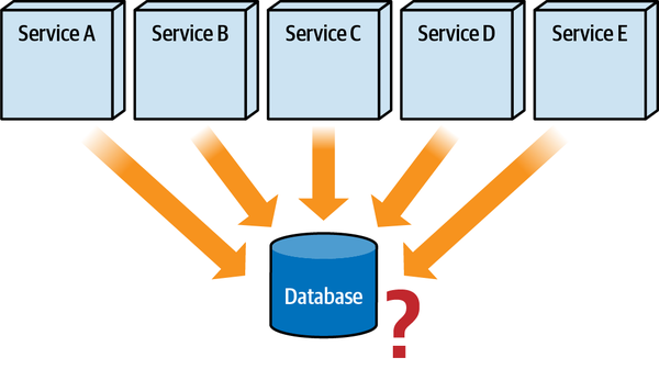
Figure 6-1. Under what circumstances should a monolithic database be decomposed?
In this section, we will explore the data disintegrators and data integrators used to help make the right choice when considering breaking apart monolithic data.
Data Disintegrators
Data disintegration drivers provide answers and justifications
- Change control
-
How many services are impacted by a database table change?
- Connection management
-
Can my database handle the connections needed from multiple distributed services?
- Scalability
-
Can the database scale to meet the demands of the services accessing it?
- Fault tolerance
-
How many services are impacted by a database crash or maintenance downtime?
- Architectural quanta
-
Is a single shared database forcing me into an undesirable single architecture quantum?
- Database type optimization
-
Can I optimize my data by using multiple database types?
Each of these disintegration drivers is discussed in detail in the following sections.
Change control
As illustrated in Figure 6-2, when breaking changes occur to a database, multiple services must be updated, tested, and deployed together with the database changes. This coordination can quickly become both difficult and error prone as the number of separately deployed services sharing the same database increases. Imagine trying to coordinate 42 separately deployed services for a single breaking database change!
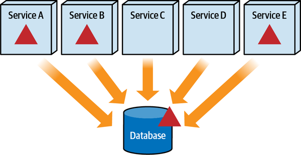
Figure 6-2. Services impacted by the database change must be deployed together with the database
Coordinating changes to multiple distributed services for a shared database change is only half the story.
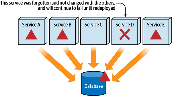
Figure 6-3. Services impacted by a database change but forgotten will continue to fail until redeployed
In most applications, the danger of forgotten services is mitigated by diligent impact analysis and agressive regression testing. However, consider a microservices ecosystem with 400 services, all sharing the same monolithic highly available clustered relational database. Imagine running around to all the development teams in many domain areas, trying to find out which services use the table being changed. Also imagine having to then coordinate, test, and deploy all of these services together as a single unit, along with the database. Thinking about this scenario starts to become a mind-numbing exercise, usually leading to some degree of insanity.
Breaking apart a database into well-defined bounded contexts significantly
Most typically, bounded contexts are formed around services and the data
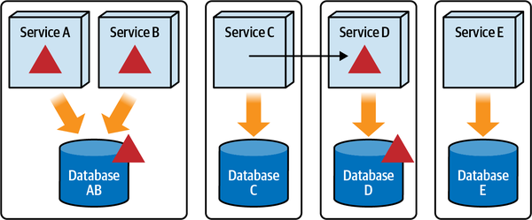
Figure 6-4. Database changes are isolated to only those services within the associated bounded context
Notice in Figure 6-4 that Service C needs access to some of the data in Database D that is contained in a bounded context with Service D. Since Database D is in a different bounded context, Service C cannot directly access the data. This would not only violate the bounded context rule, but also create a mess with regard to change control. Therefore, Service C must ask Service D for the data. There are many ways of accessing data a service doesn’t own while still maintaining a bounded context. These techniques are discussed in detail in Chapter 10.
One important aspect of a bounded context related to the scenario between Service C needing data and Service D
The advantage of the bounded context is that the data sent to Service C can be a different contract than the schema for Database D. This means that a breaking change to some table in Database D impacts only Service D and not necessarily the contract of the data sent to Service C. In other words, Service C is abstracted from the actual schema structure of Database D.
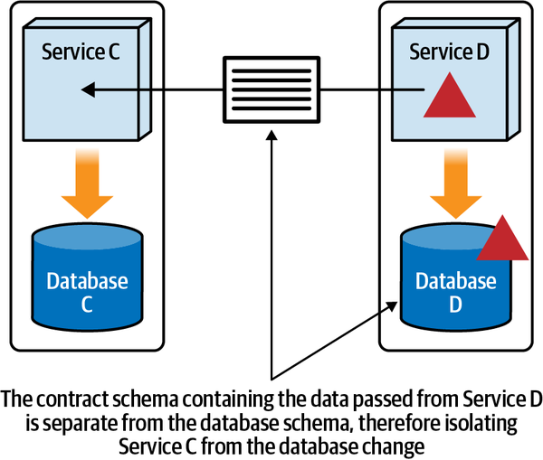
Figure 6-5. The contract from a service call abstracts the caller from the underlying database schema
To illustrate the power of this bounded context abstraction within a distributed architecture, assume Database D has a Wishlist table with the following structure:
CREATETABLEWishlist(CUSTOMER_IDVARCHAR(10),ITEM_IDVARCHAR(20),QUANTITYINT,EXPIRATION_DTDATE);
The corresponding JSON contract that Service D sends to Service C requesting wish list items is as follows:
{"$schema":"http://json-schema.org/draft-04/schema#","properties":{"cust_id":{"type":"string"},"item_id":{"type":"string"},"qty":{"type":"number"},"exp_dt":{"type":"number"}},}
Notice how the expiration data field (exp_dt) in the JSON schema is named differently than the database column name and is specified as a number (a long value representing the epoch time—the number of milliseconds since midnight on 1 January 1970), whereas in the database it is represented as a DATE field. Any column name change or column type change made in the database no longer impacts Service C because of the separate JSON contract.
To illustrate this point, suppose the business decides to no longer expire wish list items. This would require a change in the table structure of the database:
ALTERTABLEWishlistDROPCOLUMNEXPIRATION_DT;
Service D would have to be modified to accommodate this change because it is within the same bounded context as the database, but the corresponding contract would not have to change at the same time. Until the contract is eventually changed, Service D could either specify a date far into the future or set the value to zero indicating the item doesn’t expire. The bottom line is that Service C is abstracted from breaking changes made to Database D due to the bounded context.
Connection management
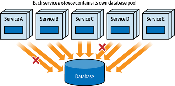
Figure 6-6. Database connections can quickly get saturated with multiple service instances
Reaching (or exceeding) the maximum number of available database connections is yet another driver to consider when deciding whether to break apart a database. Frequent connection waits (the amount of time it takes waiting for a connection to become available) is usually the first sign that the maximum number of database connections has been reached. Since connection waits can also manifest themselves as request time-outs or tripped circuit breakers, looking for connection waits is usually the first thing we recommend if these conditions frequently occur when using a shared database.
To illustrate the issues associated with database connections and distributed architecture, consider the following example: a monolithic application with 200 database connections is broken into a distributed architecture consisting of 50 services, each with 10 database connections in its connection pool.
Original monolithic application | 200 connections |
Distributed services | 50 |
Connections per service | 10 |
Minimum service instances | 2 |
Total service connections | 1,000 |
Notice how the number of database connections within the same application context grew from 200 to 1,000, and the services haven’t even started scaling yet! Assuming half of the services scale to an average of 5 instances each, the number of database connections quickly grows to 1,700.
Without some sort of connection strategy or governance plan, services
By specifying a connection quota, services are not allowed to create more database connections than are allocated to it. If a service reaches the maximum number of database connections in its quota, it must wait for one of the connections it’s using to become available. This method can be implemented using two approaches: evenly distributing the same connection quota to every service, or assigning a different connection quota to each service based on its needs.
The even distribution approach is typically used when first deploying services, and it is not known yet how many connections each service will need during normal and peak operations. While simple, this approach is not overly efficient because some services may need more connections than others, while some connections held by other services may go unused.
While more complex, the variable distribution approach is much more efficient for managing database connections to a shared database. With this approach, each service is assigned a different connection quota based on its functionality and scalability requirements. The advantage of this approach is that it optimizes the use of available database connections across distributed services, making sure those services that require more database connections have them available for use. However, the disadvantage is that it requires knowledge about the nature of the functionality and the scalability requirements of each service.
We usually recommend starting out with the even distribution approach and creating fitness functions to measure the concurrent connection usage for each service. We also recommend keeping the connection quota values in an external configuration server (or service) so that the values can be easily adjusted either manually or programmatically through simple machine learning algorithms. This technique not only helps mitigate connection saturation risk, but also properly balances available database connections between distributed services to ensure that no idle connections are wasted.
| Service | Quota | Max used | Waits | |
|---|---|---|---|---|
A | 20 | 5 | No | |
→ | B | 20 | 20 | Yes |
C | 20 | 15 | No | |
→ | D | 20 | 20 | Yes |
E | 20 | 14 | No |
Since Service A is well below its connection quota, this is a good place to start reallocating connections to other services. Moving five database connections to Service B and five database connections to Service D yields the results shown in Table 6-2.
| Service | Quota | Max used | Waits | |
|---|---|---|---|---|
A | 10 | 5 | No | |
→ | B | 25 | 25 | Yes |
C | 20 | 15 | No | |
D | 25 | 25 | No | |
E | 20 | 14 | No |
This is better, but Service B is still experiencing connection waits, indicating that it requires more connections than it has in its connection quota. Readjusting the quotas even further by taking two connections each from Service A and Service E yields much better results, as shown in Table 6-3.
| Service | Quota | Max used | Waits |
|---|---|---|---|
A | 8 | 5 | No |
B | 29 | 27 | No |
C | 20 | 15 | No |
D | 25 | 25 | No |
E | 18 | 14 | No |
This analysis, which can be derived from continuous fitness functions that gather streamed metrics data from each service, can also be used to determine how close the maximum number of connections used is to the maximum number of connections available, and also how much buffer exists for each service in terms of its quota and maximum connections used.
Scalability
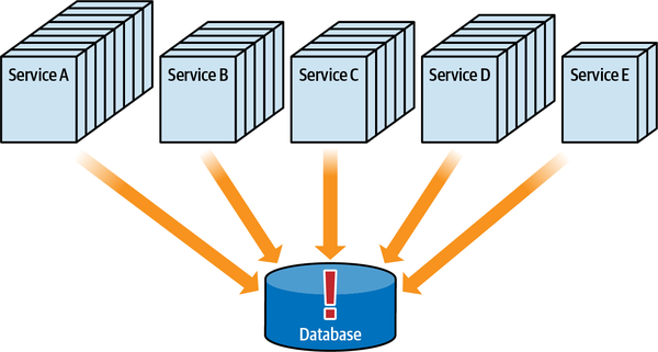
Figure 6-7. The database must also scale when services scale
Scalability is another data disintegration driver to consider when thinking about breaking apart a database. Database connections, capacity, throughput, and performance are all factors in determining whether a shared database can meet the demands of multiple services within a distributed architecture.
| Service | Quota | Max used | Instances | Total used |
|---|---|---|---|---|
A | 8 | 5 | 2 | 10 |
B | 29 | 27 | 3 | 81 |
C | 20 | 15 | 3 | 45 |
D | 25 | 25 | 2 | 50 |
E | 18 | 14 | 4 | 56 |
TOTAL | 100 | 86 | 14 | 242 |
Notice that even though the connection quota is distributed to match the 100 database connections available, once services start to scale, the quota is no longer valid because the total number of connections used increases to 242, which is 142 more connections than are available in the database. This will likely result in connection waits, which in turn will result in overall performance degradation and request time-outs.
Breaking data into separate data domains or even
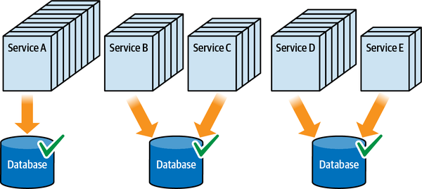
Figure 6-8. Breaking apart the database provides better database scalability
In addition to database connections, another factor to consider with respect to scalability is the load placed on the database. By breaking apart a database, less load is placed on each database, thereby also improving overall performance and scalability.
Fault tolerance
When multiple services share the same database, the overall
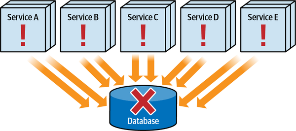
Figure 6-9. If the database goes down, all services become nonoperational
Fault tolerance is another driver for considering breaking apart data. If fault tolerance is required for certain parts of the system, breaking apart the data can remove the single point of failure in the system, as shown in Figure 6-10. This ensures that some parts of the system are still operational in the event of a database crash.
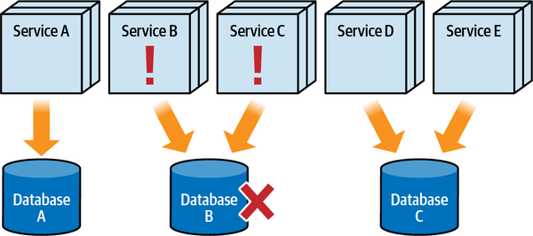
Figure 6-10. Breaking apart the database achieves better fault tolerance
Notice that since the data is now broken apart, if Database B goes down, only Service B and Service C are impacted and become nonoperational, whereas the other services continue to operate uninterrupted.
Architectural quantum
Recall from Chapter 2 that an architectural quantum
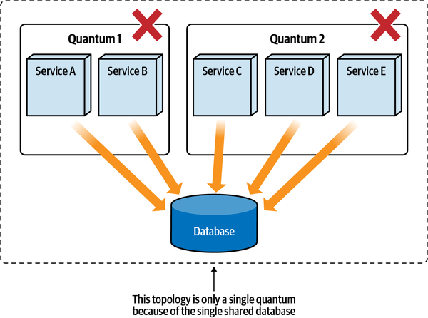
Figure 6-11. The database is part of the architectural quantum
Because the database is included in the functional cohesion part of the architecture quantum definition,
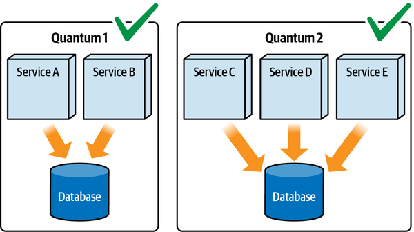
Figure 6-12. Breaking up the database forms two architectural quanta
Database type optimization
It’s often the case that not all data is treated the same.
Data Integrators
Data integrators do the exact opposite of the data disintegrators discussed in the prior section.
The two main integration drivers for pulling data back together are the following:
- Data relationships
-
Are there foreign keys, triggers, or views that form close relationships between the tables?
- Database transactions
-
Is a single transactional unit of work necessary to ensure data integrity and consistency?
Each of these integration drivers is discussed in detail in the following sections.
Data relationships
Imagine walking up to your DBA or data architect and telling them that since the database must be broken apart to support tightly formed bounded contexts within a microservices ecosystem, every foreign key and view in the database needs to be removed! That’s not a likely (or even feasible) scenario, yet that is precisely what would need to happen to support a database-per-service pattern in microservices.
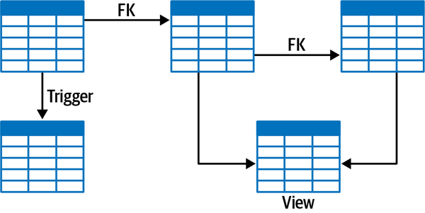
Figure 6-13. Foreign keys (FK), triggers, and views create tightly coupled relationships between data
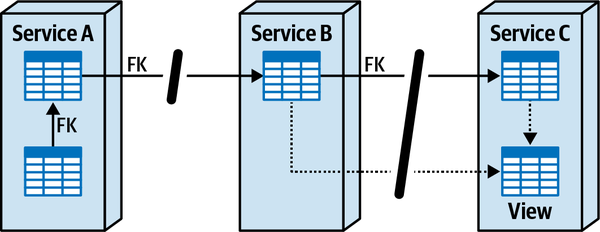
Figure 6-14. Data artifacts must be removed when breaking apart data
Notice that the foreign key (FK) relationship between the tables in Service A can be preserved because the data is in the same bounded context, schema, or database. However, the foreign keys (FK) between the tables in Service B and Service C must be removed (as well as the view that is used in Service C) because those tables are associated with different databases or schemas.
The relationship between data, either logical or physical, is a data integration driver, thus creating a trade-off between data disintegrators and data integrators. For example, is change control (a data disintegrator) more important than preserving the foreign key relationships between the tables (a data integrator)? Is fault tolerance (a data disintegrator) more important than preserving materialized views between tables (a data integrator)? Identifying what is more important helps make the decision about whether the data should be broken apart and what the resulting schema granularity should be.
Database transactions
Another data integrator is that of database transactions,
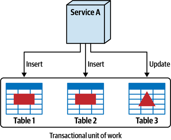
Figure 6-15. A single transactional unit of work exists when the data is together
However, when data is broken apart into either separate schemas or databases, as illustrated in Figure 6-16, a single transactional unit of work no longer exists because of the remote calls between services. This means that an insert or update can be committed in one table, but not in the other tables because of error conditions, resulting in data consistency and integrity issues.
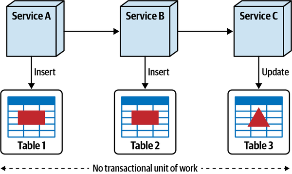
Figure 6-16. Single unit of work transactions don’t exist when data is broken apart
While we dive into the details of distributed transaction management and transactional sagas in Chapter 12, the point here is to emphasize that database transactions are yet another data integration driver, and should be taken into account when considering breaking apart a database.
Sysops Squad Saga: Justifying Database Decomposition
Monday, November 15, 15:55
“Hi, Dana,” said Addison. “We think we have enough evidence to convince you that it’s necessary to break apart the Sysops Squad database.”
“I’m all ears,” said Dana, arms crossed and ready to argue that the database should remain as is.
“I’ll start,” said Addison. “Notice how these logs continuously show that whenever the operational reports run, the ticketing functionality in the application freezes up?”
“Yeah,” said Dana, “I’ll admit that even I suspected that. It’s clearly something wrong with the way the ticketing functionality is accessing the database, not reporting.”
“Actually,” said Addison, “it’s a combination of both ticketing and reporting. Look here.”
Addison showed Dana metrics and logs that demonstrated some of the queries were necessarily wrapped in threads, and that the queries from the ticketing functionality were timing out because of a wait state when the reporting queries were run. Addison also showed how the reporting part of the system used parallel threads to query parts of the more complex reports concurrently, essentially taking up all of the database connections.
“OK, I can see how having a separate reporting database would help the situation from a database connection perspective. But that still doesn’t convince me that the nonreporting data should be broken apart,” said Dana.
“Speaking of database connections,” said Devon, “look at this connection pool estimate as we start breaking apart the domain services.”
“So you see, Dana,” said Devon, “with these projected estimates, we will need an additional 2,000 connections to the database to provide the scalability we need to handle the ticket load, and we simply do not have them with a single database.”
Dana took a moment to look over the numbers. “Do you agree with these numbers, Addison?”
“I do,” said Addison. “Devon and I came up with them ourselves after a lot of analysis based on the amount of HTTP traffic as well as the projected growth rates supplied by Parker.”
“I must admit,” said Dana, “this is good stuff you’ve both prepared. I particularly like that you’ve already thought about not having services connect to multiple databases or schemas. As you know, in my book that’s a no-go.”
“What Addison is saying,” added Devon, “is that by breaking apart the database, we can provide better fault tolerance by creating domain silos for the data. In other words, if the survey database were to go down, ticketing functionality would still be available.”
“Listen,” said Dana, “you’ve convinced me that there’s good reasons to break apart the Sysops Squad database, but explain to me how you can even think about doing that. Do you realize how many foreign keys and views there are in that database? There’s no way you’re going to be able remove all of those things.”
“We don’t necessarily have to remove all of those artifacts. That’s where data domains and the five-step process come into play,” said Devon. “Here, let me explain…”
Decomposing Monolithic Data
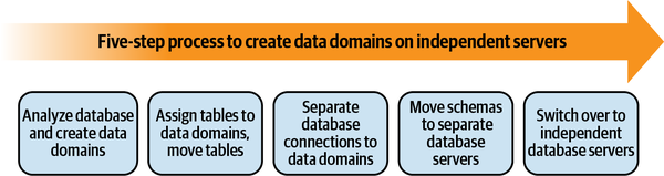
Figure 6-17. Five-step process for decomposing a monolithic database
A data domain is a collection of coupled database
| Table | Proposed data domains |
|---|---|
customer | Customer |
customer_notification | Customer |
survey | Survey |
question | Survey |
survey_administered | Survey |
survey_question | Survey |
survey_response | Survey |
billing | Payment |
contract | Payment |
payment_method | Payment |
payment | Payment |
sysops_user | Profile |
profile | Profile |
expert_profile | Profile |
expertise | Profile |
location | Profile |
article | Knowledge Base |
tag | Knowledge Base |
keyword | Knowledge Base |
article_tag | Knowledge Base |
article_keyword | Knowledge Base |
ticket | Ticketing |
ticket_type | Ticketing |
ticket_history | Ticketing |
Table 6-5 lists six data domains within the Sysops Squad application: Customer, Survey, Payment, Profile, Knowledge base, and Ticketing. The billing table belongs to the Payment data domain, ticket and ticket_type tables belong to the Ticketing data domain, and so on.
One way to conceptually think about data domains is to think
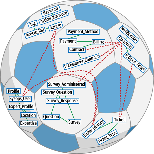
Figure 6-18. Database objects in a hexagon belong in a data domain
Visualizing the database this way allows the architect and database team to clearly
When extracting a data domain, these cross-domain dependencies must be removed. This means removing foreign-key constraints, views, triggers, functions, and stored procedures between data domains.
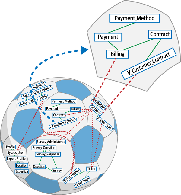
Figure 6-19. Tables belonging to data domains, extracted out, and connections that need to be broken
customer table belongs to a different data domain than the v_customer_contract, the customer table must be removed from the view in the Payment domain. The original view v_customer_contract prior to defining the data domain is defined in Example 6-1. Example 6-1. Database view to get open tickets for customer with cross-domain joins
CREATEVIEW[payment].[v_customer_contract]ASSELECTcustomer.customer_id,customer.customer_name,contract.contract_start_date,contract.contract_duration,billing.billing_date,billing.billing_amountFROMpayment.contractAScontractINNERJOINcustomer.customerAScustomerON(contract.customer_id=customer.customer_id)INNERJOINpayment.billingASbillingON(contract.contract_id=billing.contract_id)WHEREcontract.auto_renewal=0
Notice in the updated view shown in Example 6-2 that the join between customer and payment tables is removed, as is the column for the customer name (customer.customer_name).
Example 6-2. Database view to get open tickets in ticket domain for a given customer
CREATEVIEW[payment].[v_customer_contract]ASSELECTbilling.customer_id,contract.contract_start_date,contract.contract_duration,billing.billing_date,billing.billing_amountFROMpayment.contractAScontractINNERJOINpayment.billingASbillingON(contract.contract_id=billing.contract_id)WHEREcontract.auto_renewal=0
The bounded context rules for data domains apply just the same as individual
Once architects and database teams understand the concept of a data domain, they can apply the five-step process for decomposing a monolithic database. Those five steps are outlined in the following sections.
Step 1: Analyze Database and Create Data Domains
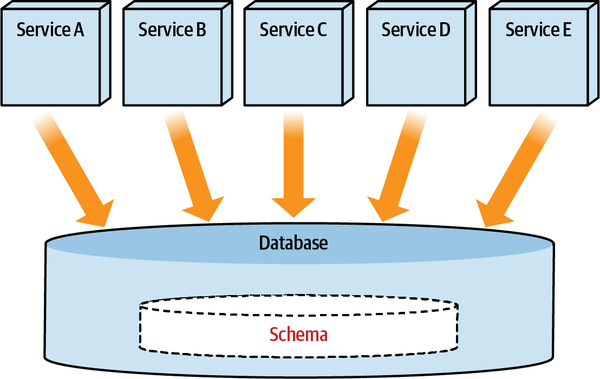
Figure 6-20. Multiple services use the same database, accessing all the tables necessary for read or write purposes
The first step in breaking apart a database is to identify specific domain groupings within the database. For example, as shown in Table 6-5, related tables are grouped together to help identify possible data domains.
Step 2: Assign Tables to Data Domains
The next step is to group tables along a specific bounded context, assigning
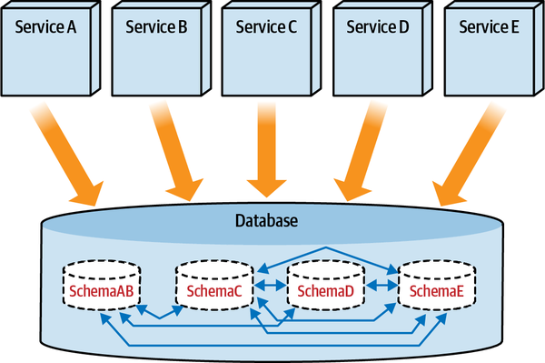
Figure 6-21. Services use the primary schema according to their data domain needs
When tables belonging to different data domains are tightly coupled
To illustrate the assignment of tables to schemas, consider the Sysops Squad example where the billing table must be moved from its original schema to another data domain schema called payment:
ALTERSCHEMApaymentTRANSFERsysops.billing;
To illustrate this practice, consider the following cross-domain query:
SELECThistory.ticket_id,history.notes,agent.nameFROMticket.ticket_historyAShistoryINNERJOINprofile.sysops_userASagentON(history.assigned_to_sysops_user_id=agent.sysops_user_id)
Next, create a synonym for the profile.sysops_user table in the ticketing schema:
CREATESYNONYMticketing.sysops_userFORprofile.sysops_user;GO
As a result, the query can leverage the synonym sysops_user rather than the cross-domain table:
SELECThistory.ticket_id,history.notes,agent.nameFROMticket.ticket_historyAShistoryINNERJOINticket.sysops_userASagentON(history.assigned_to_sysops_user_id=agent.sysops_user_id)
Unfortunately, creating synonyms this way for tables that are accessed across schemas provides the application developers with coupling points. To form proper data domains, these coupling points need to be broken apart at some later time, therefore moving the integration points from the database layer to the application layer.
Step 3: Separate Database Connections to Data Domains
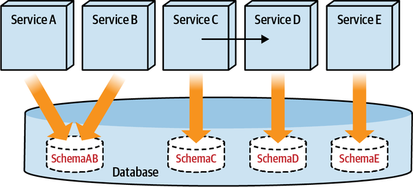
Figure 6-22. Move the cross-schema object access to the services, away from direct cross-schema access
Tip
When data from other domains is needed, do not reach into their databases. Instead, access it using the service that owns the data domain.
Upon completion of this step, the database is in a
- Benefits
-
-
Teams can change the database schema without worrying about affecting changes in other domains.
-
Each service can use the database technology and database type best suitable for their use case.
-
- Shortcomings
-
-
Performance issues occur when services need access to large volumes of data.
-
Referential integrity cannot be maintained in the database, resulting in the possibility of bad data quality.
-
All database code (stored procedures, functions) that access tables belonging to other domains must be moved to the service layer.
-
Step 4: Move Schemas to Separate Database Servers
When moving schemas to separate physical databases, database teams have two options: backup and restore, or replication. These options are outlined as follows:
- Backup and restore
-
With this option, teams first back up each schema with data
domains, then set up database servers for each data domain. They then restore the schemas, connect services to schemas in the new database servers, and finally remove schemas from the original database server. This approach usually requires downtime for the migration. - Replicate
- Using the replicate option, teams first set up database servers foreach data domain. Next they replicate the schemas, switch connections over to the new database servers, and then remove the schemas from the original database server. While this approach avoids downtime, it does require more work to set up the replication and manage increased coordination.
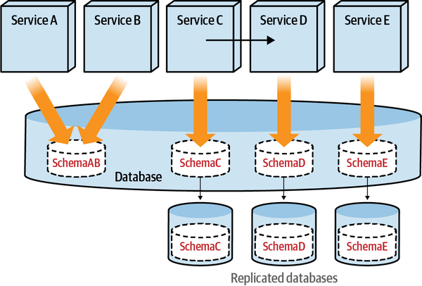
Figure 6-23. Replicate schemas (data domains) to their own database servers
Step 5: Switch Over to Independent Database Servers
Once the schemas are fully replicated, the service connections can be switched.
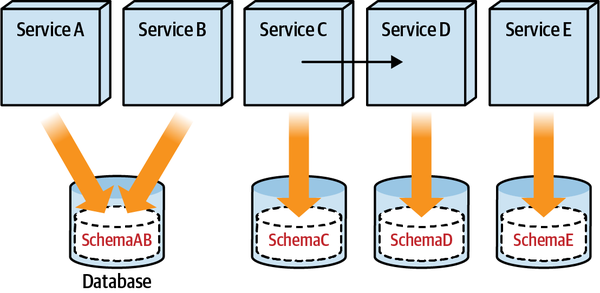
Figure 6-24. Independent database servers for each data domain
Once the database team has separated the data domains, isolated the database connections, and finally moved the data domains to their own database servers, they can optimize the individual database servers for availability and scalability. Teams can also analyze the data to determine the most appropriate database type to use, introducing polyglot database usage within the ecosystem.
Selecting a Database Type
Beginning around 2005, a revolution has occurred in database
In this section, we introduce star ratings for the various database types, using the following characteristics in our analysis:
- Ease-of-learning curve
-
This characteristic refers to the ease with which new developers, data architects, data modelers, operational DBAs, and other users of the databases can learn and adopt. For example, it’s assumed that most software developers understand SQL, whereas something like Gremlin (a graph query language) may be a niche skill. The higher the star rating, the easier the learning curve. The lower the star rating, the harder the learning curve.
- Ease of data modeling
-
This characteristic refers to the ease with which data modelers can represent the domain in terms of a data model. A higher star rating means data modeling matches many use cases, and once modeled, is easy to change and adopt.
- Scalability/throughput
-
This characteristic refers to the degree and ease with which a database can scale to handle increased throughput. Is it easy to scale the database? Can the database scale horizontally, vertically, or both? A higher star rating means it’s easier to scale and get higher throughput.
- Availability/partition tolerance
-
This characteristic refers to whether
the database supports high availability configurations (such as replica-sets in MongoDB or tunable consistency inApache Cassandra). Does it provide features to handle network partitions? The higher the star rating, the better the database supports higher availability and/or better partition tolerance. - Consistency
-
This characteristic refers to whether the database supports an “always consistent” paradigm.
Does the database support ACID transactions, or does it lean toward BASE transactions with an eventual consistency model? Does it provide features to have tunable consistency models for different types of writes? The higher the star rating, the more consistency the database supports. - Programming language support, product maturity, SQL support, and community
-
This characteristic refers to which (and how many) programming languages the database supports, how mature the database is, and the size of the database community. Can an organization easily hire people who know how to work with the database? Higher star ratings means there is better support, the product is mature, and it’s easy to hire talent.
- Read/write priority
-
This characteristic refers to whether the database prioritizes reads over writes, or writes over reads, or if it is balanced in its approach. This is not a binary choice—rather, it’s more of a scale toward which direction the database optimizes.
Relational Databases
read models on top of the same write model. The star ratings for relational databases appear in 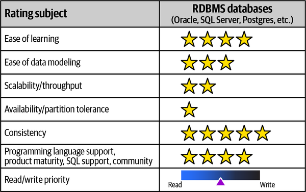
Figure 6-25. Relational databases rated for various adoption characteristics
- Ease-of-learning curve
-
Relational databases have been around for many years. They are commonly taught in schools, and mature documentation and tutorials exist. Therefore, they are much easier to learn than other database types.
- Ease of data modeling
-
Relational databases allow for flexible data modeling. They allow the modeling of key-value, document, graph-like structures, and they allow for changes in read patterns with addition of new indexes. Some models are really difficult to achieve, such as graph structures with arbitrary depth. Relational databases organize data into tables and rows (similar to spreadsheets), something that is natural for most database modelers.
- Scalability/throughput
-
Relational databases are generally vertically scaled using large machines.
However, setup with replications and automated switchover are complex, requiring higher coordination and setup. - Availability/partition tolerance
- Relational databases favor consistency over availability and partition tolerance, discussed in“Table Split Technique”.
- Consistency
- Relational databases have been dominant for years because of their support for ACID properties.The ACID features handle many concerns in concurrent systems and allow for developing applications without being concerned about lower-level details of concurrency and how the databases handle them.
- Programming language support, product maturity, SQL support, and community
-
Since relational databases have been around for many years, well-known design, implementation, and operational patterns can be applied to them, thus making them easy to adopt, develop, and integrate within an architecture. Many of the relational databases lack support for reactive stream APIs and similar new concepts; newer architectural concepts take longer to implement in well-established relational databases. Numerous programming language interfaces work with relational databases, and the community of users is large (although splintered among all the vendors).
- Read/write priority
-
In relational databases, the data model can be designed in such a way that either reads become more efficient or writes become more efficient. The same database can handle different types of workloads, allowing for balanced read-write priority. For example, not all use cases need ACID properties, especially in large data and traffic scenarios, or when really flexible schema is desired such as in survey administration. In these cases, other database types may be a better option.
Key-Value Databases
ID column as the key and a blob column as the value, which can consequently store any type of data. Key-value databases are easiest to understand among the NoSQL databases. An application client can insert a key and a value, get a value for a known key, or delete a known key and its value. A key-value database does not know what’s inside the value part, nor does it care what’s inside, meaning that the database can query using the key and nothing else.
joins, where, and order by are not supported, but rather the operations get, put, and delete. The ratings for key-value databases appear in 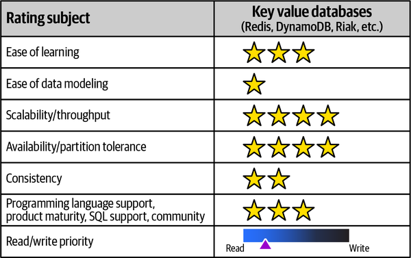
Figure 6-26. Key-value databases rated for various adoption characteristics
- Ease-of-learning curve
-
Key-value databases are easy to understand. Since they
use“Aggregate Orientation”, it’s important to design the aggregate properly because any change in the aggregate means rewriting all the data. Moving from relational databases to any of the NoSQL databases takes practice and unlearning familiar practices. For example, a developer cannot simply query “Get me all the keys.” - Ease of data modeling
-
Since key-value databases are aggregate oriented, they can use memory structures like arrays, maps, or any other type of data, including big blob. The data can be queried only by key or ID, which means the client should have access to the key outside of the database. Good examples of a key include
session_id,user_id, andorder_id. - Scalability/throughput
-
Since key-value databases are indexed by key or ID, key
lookups are very fast as there are nojoinsororder byoperations. The value is fetched and returned to the client, which allows for easier scaling and higher throughput. - Availability/partition tolerance
- Since there are many types of key-value databases andeach has different properties, even the same database can be configured to act in different ways either for an installation or for each read. For example, in Riak users can use quorum properties such as
all,one,quorum, anddefault. When we use one quorum, the query can returnsuccesswhen any one node responds. When theallquorum is used, all nodes have to respond for the query to returnsuccess. Each query can tune the partition tolerance and availability. Hence, assuming that all key-value stores are the same is a mistake. - Consistency
- During each write operation, we can apply configurations that are similarto applying quorum during read operations; these configurations provide what is known as tunable consistency. Higher consistency can be achieved by trading off latency. For a write to be highly consistent, all nodes have to respond, which reduces partition tolerance. Using a majority quorum is considered a good trade-off.
- Programming language support, product maturity, SQL support, and community
-
Key-value databases have good programming language support, and many open source databases have an active community to help learn and understand them. Since most databases have an HTTP REST API, they are much easier to interface with.
- Read/write priority
- Since key-value databases are aggregate oriented, access to data via a key or ID is geared toward read priority. Key-value databases can be used for session storage, and can be used to cache user properties and preferences as well.
Document Databases
Documents such as JSON or XML are the basis of document databases.
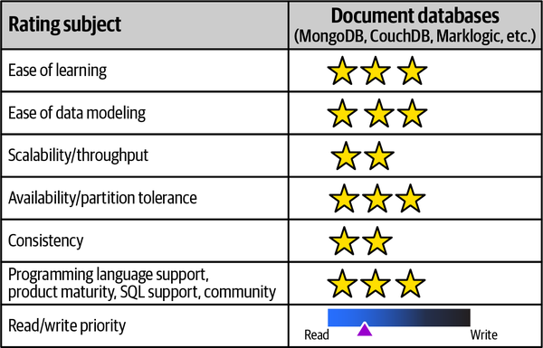
Figure 6-27. Document databases rated for various adoption characteristics
- Ease-of-learning curve
-
Document databases are like key-value databases where the value is human readable. This makes learning the database much easier. Enterprises are used to dealing with documents, such as XML and JSON in different contexts, such as API payloads and JavaScript frontends.
- Ease of data modeling
-
Just like key-value databases, data modeling involves modeling aggregates such as orders, tickets, and other domain objects. Document databases are forgiving when it comes to aggregate design, as the parts of the aggregate are queryable and can be indexed.
- Scalability/throughput
-
Document databases are aggregate oriented and easy to
scale. Complex indexing reduces scalability, and increased data size leads to a need for partitioning or sharding. Once sharding is introduced, it increases the complexity and also forces the selection of a sharding key. - Availability/partition tolerance
- Like key-value databases, document databases can be configuredfor higher availability. The setup gets complicated when there are replicated clusters for sharded collections. The cloud providers are trying to make these setups more usable.
- Consistency
- Some document databases have started supporting ACIDtransactions within a collection, but this may not work in some edge cases. Just like key-value databases, document databases provide the ability to tune the read and write operations using the quorum mechanism.
- Programming language support, product maturity, SQL support, and community
-
Document databases are the most popular of the NoSQL databases, with an active user community, numerous online learning tutorials, and many programming language drivers that allow for easier adoption.
- Read/write priority
-
Document databases are aggregate oriented and have secondary indexes to query, so these databases are favoring read priority.
Column Family Databases
name is known as a column-key, the value is known as a column-value, and the primary key of a row is known as a row key. Column family databases are another type of NoSQL database that group related data that is accessed at the same time, and whose ratings appear in 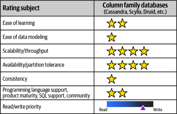
Figure 6-28. Column family databases rated for various adoption characteristics
- Ease-of-learning curve
-
Column family databases are difficult to understand. Since a collection of name-value pairs belong to a row, each row can have different name-value pairs. Some name-value pairs can have a map of columns and are known as super columns. Understanding how to use these takes practice and time.
- Ease of data modeling
-
Data modeling with column family databases takes some getting used to. Data needs to be arranged in groups of name-value pairs that have a single row identifier, and designing this row key takes multiple iterations.
Some column family databases like Apache Cassandra have introduced a SQL-like query language known as Cassandra Query Language (CQL) that makes data modeling accessible. - Scalability/throughput
- All column family databases are highly scalable and suit usecases where high write or read throughput is needed. Column family databases scale horizontally for read and write operations.
- Availability/partition tolerance
- Column family databases naturally operate in clusters, and whensome nodes of the cluster are down, it is transparent to the client. The default replication factor is three, which means at least three copies of data are made, improving availability and partition tolerance. Similar to key-value and document databases, column family databases can tune writes and reads based on quorum needs.
- Consistency
- Column family databases, like other NoSQL databases, followthe concept of tunable consistency. This means that, based on needs, each operation can decide how much consistency is desired. For example, in
high writescenarios where some data loss can be tolerated, the write consistency level ofANYcould be used, which means at least one node has accepted the write, while a consistency level ofALLmeans all nodes have to accept the write and respond success. Similar consistency levels can be applied to read operations. It’s a trade-off—higher consistency levels reduce availability and partition tolerance. - Programming language support, product maturity, SQL support, and community
- Column family databases like Cassandra and Scyllahave active communities, and the development of SQL-like interfaces has made the adoption of these databases easier.
- Read/write priority
-
Column family databases use the concepts of SSTables, commit logs, and memtables, and since the name-value pairs are populated when data is present, they can handle sparse data much better than relational databases. They are ideal for high write-volume scenarios.
Graph Databases
Unlike relational databases, where relations are implied based on
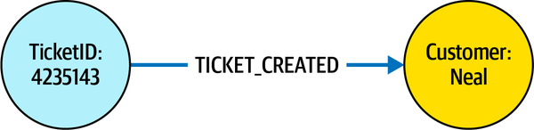
Figure 6-29. In graph databases, direction of the edge has significance when querying
TICKET_CREATED connecting a ticket node with ID 4235143 to a customer node with ID Neal. We can traverse from the ticket node via the outgoing edge TICKET_CREATED or the customer node via the incoming edge TICKET_CREATED. When the directions get mixed up, querying the graph becomes really difficult. The ratings for graph databases are illustrated in 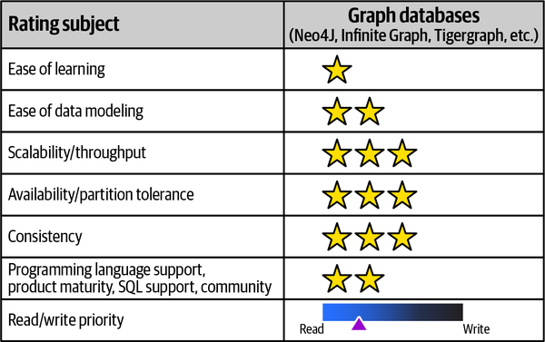
Figure 6-30. Graph databases rated for various adoption characteristics
- Ease-of-learning curve
-
Graph databases have a steep learning curve. Understanding how to use the nodes, relations, relation type, and properties takes time.
- Ease of data modeling
-
Understanding how to model the domains and convert them into nodes and relations is hard. In the beginning, the tendency is to add properties to relations. As modeling knowledge improves, increased usage of nodes and relations, and converting some relation properties to nodes with additional relation type takes place, which improves graph traversal.
- Scalability/throughput
-
Replicated nodes improve read scaling, and throughput can be tuned for read loads.
Since it’s difficult to split or shard graphs, write throughput is constrained with the type of graph database picked. Traversing the relationships is very fast, as the indexing and storage is persisted and not calculated at query time. - Availability/partition tolerance
- Some of the graph databases that have high partition toleranceand availability are distributed. Graph database clusters can use nodes that can be promoted as leaders when current leaders are unavailable.
- Consistency
- Many graph databases support ACID transactions. Some graphdatabases, such asNeo4j, support transactions, so that data is always consistent.
- Programming language support, product maturity, SQL support, and community
-
Graph databases have lots of support in the community. Many algorithms, like Dijkstra’s algorithm or node similarity, are implemented in the database, reducing the need to write them from scratch.
The language framework known as Gremlin works across many different databases, helping in the ease of use.Neo4J supports a query language known as Cypher, allowing developers to easily query the database. - Read/write priority
-
In graph databases, data storage is optimized for relationship traversal as opposed to relational databases, where we have to query the relationships and derive them at query time. Graph databases are better for read-heavy scenarios.
Graph databases allow the same node to have various types of relationships. In the Sysops Squad example, a sample graph might look as follows: a knowledge_base was created_by user sysops_user and knowledge_base used_by sysops_user. Thus, the relationships created_by and used_by join the same nodes for different relationship types.
NewSQL Databases
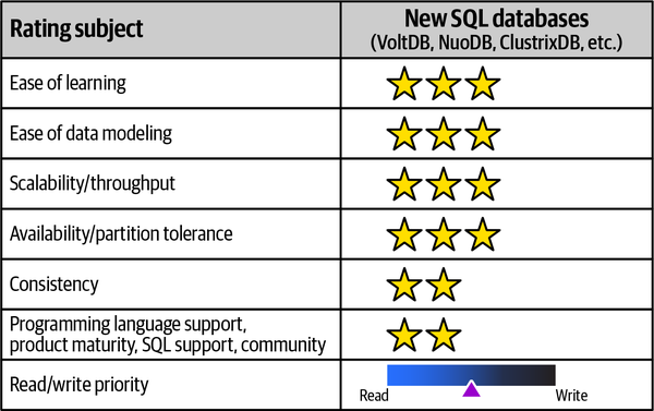
Figure 6-31. New SQL databases rated for various adoption characteristics
- Ease-of-learning curve
-
Since NewSQL databases are just like relational databases (with SQL interface, added features of horizontal scaling, ACID compliant), the learning curve is much easier.
Some of them are available as only Database as a Service (DBaaS), which may make learning them more difficult. - Ease of data modeling
- Since NewSQL databases are like relational databases, data modeling is familiar to many and easier to pick up.The extra wrinkle is sharding design, allowing sharded data placement in geographically different locations.
- Scalability/throughput
- NewSQL databases are designed to support horizontal scalingfor distributed systems, allowing for multiple active nodes, unlike relational databases that have only one active leader, and the rest of the nodes are followers. The multiple active nodes allow NewSQL databases to be highly scalable and to have better throughput.
- Availability/partition tolerance
- Because of the multiple active nodes design, the benefits toavailability can be really high with greater partition tolerance. CockroachDB is a popular NewSQL database that survives disk, machine, and data center failures.
- Consistency
- NewSQL databases support strongly consistent ACIDtransactions. The data is always consistent, and this allows for relational database users to easily transition to NewSQL databases.
- Programming language support, product maturity, SQL support, and community
-
There are many open source NewSQL databases, so learning them is accessible. Some of the databases also support wire-compatible protocols with existing relational databases, which allows them to replace relational databases without any compatibility problems.
- Read/write priority
-
NewSQL databases are used just like relational databases, with added benefits of indexing and distributing geographically either to improve read performance or write performance.
Cloud Native Databases
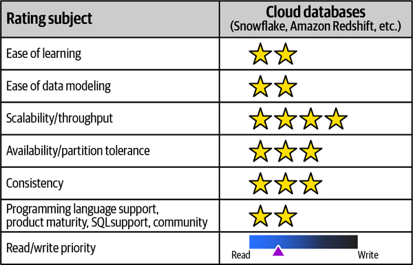
Figure 6-32. Cloud native databases rated for various adoption characteristics
- Ease-of-learning curve
-
Some cloud databases like AWS Redshift are like relational databases and therefore are easier to understand. Databases like Snowflake, which have a SQL interface but have different storage and compute mechanisms, require some practice. Datomic is totally different in terms of models and uses
immutableatomic facts. Thus, the learning curve varies with each database offering. - Ease of data modeling
-
Datomic does not have the concept of tables or the need to define attributes in advance. It is necessary to define properties of individual attributes, and entities can have any attribute. Snowflake and Redshift are used more for data warehousing type workloads. Understanding the type of modeling provided by the database is critical in selecting the database to use.
- Scalability/throughput
-
Since all these databases are cloud only, scaling them
is relatively simple since resources can be allocated automatically for a price. In these decisions, the trade-off typically relates to price. - Availability/partition tolerance
- Databases in this category (such as Datomic) are highlyavailable when deployed using Production Topology. They have no single point of failure and are supported by extensive caching. Snowflake, for example, replicates its databases across regions and accounts. Other databases in this category support higher availability with various options to configure. For example, Redshift runs in a single availability zone and would need to be run in multiple clusters to support higher availability.
- Consistency
- Datomic supports ACID transactions using storage engines tostore blocks in block storage. Other databases, like Snowflake and Redshift, support ACID transactions.
- Programming language support, product maturity, SQL support, and community
- Many of these databases are new, and finding experienced help can be difficult. Experimenting with these databases requires a cloud account, which can create another barrier. While cloud native databases reduce operational workload on the operational DBAs, they do have a higher learning curve for developers. Datomic usesClojure in all its examples, and stored procedures are written with Clojure, so not knowing Clojure maybe a barrier to usage.
- Read/write priority
-
These databases can be used for both read-heavy or write-heavy loads. Snowflake and Redshift are geared more toward data warehouse type workloads, lending them toward read priority, while Datomic can support both type of loads with different indexes such as EAVT (Entity, Attribute, Value, then Transaction) first.
Time-Series Databases
Given the trends, we see increased usage of IoT, microservices, self-driving cars,
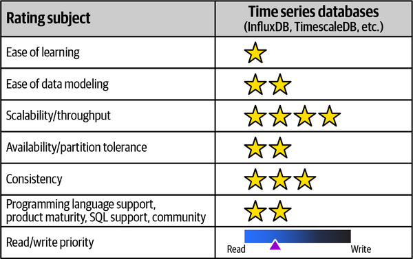
Figure 6-33. Time-series databases rated for various adoption characteristics
- Ease-of-learning curve
-
Understanding time-series data is often easy—every data point is attached to a timestamp, and data is almost always inserted and never updated or deleted. Understanding append-only operations takes some unlearning from other database usage, where errors in the data can be corrected with an update.
InfluxDB, Kx, and TimeScale are some of the popular time-series databases. - Ease of data modeling
-
The underlying concept with time-series databases is to analyze changes in data over time. For example, with the Sysops Squad example, changes done to a ticket object can be stored in a time-series database, where the
timestampof change andticket_idare tagged. It’s considered bad practice to add more than one piece of information in one tag. For example,ticket_status=Open, ticket_id=374737is better thanticket_info=Open.374737. - Scalability/throughput
- Timescale is based on PostgreSQL and allows for standard scaling and throughput improvement patterns.Running InfluxDB in cluster mode by using meta nodes that manage metadata and data nodes that store actual data provides scaling and throughput improvements.
- Availability/partition tolerance
- Some databases like InfluxDB have better availability and partitiontolerance options with configurations for meta and data nodes, along with replication factors.
- Consistency
- Time-series databases that use relational databases as theirstorage engine get ACID properties for consistency, while other databases can tune consistency using
consistency-levelofany,one, orquorum.Higher consistency-level configuration generally results in higher consistency and lower availability, so it’s a trade-off that needs to be considered. - Programming language support, product maturity, SQL support, and community
-
Time-series databases have become popular lately, and there are many resources to learn from. Some of these databases, such as InfluxDB, provide a SQL-like query language known as InfluxQL.
- Read/write priority
-
Time-series databases are append only and tend to be better suited for read-heavy workloads.
| Database type | Products |
|---|---|
Relational | PostgreSQL, Oracle, Microsoft SQL |
Key-value | Riak KV, Amazon DynamoDB, Redis |
Document | MongoDB, Couchbase, AWS DocumentDB |
Column family | Cassandra, Scylla, Amazon SimpleDB |
Graph | Neo4j, Infinite Graph, Tiger Graph |
NewSQL | VoltDB, ClustrixDB, SimpleStore (aka MemSQL) |
Cloud native | Snowflake, Datomic, Redshift |
Time-series | InfluxDB, kdb+, Amazon Timestream |
Sysops Squad Saga: Polyglot Databases
Thursday, December 16, 16:05
“I simply don’t agree,” said Dana. “The survey tables have always worked in the past as relational tables, so I see no reason to change things around. "
“Actually,” said Skyler, “if you had originally talked with us about this when the system was first being developed, you would understand that from a user interface perspective, it’s really hard to deal with relational data for something like a customer survey. So I disagree. It may work out good for you, but from a user interface development standpoint, dealing with relational data for the survey stuff has been a major pain point.”
“See, so there you are,” said Devon. “This is why we need to change it to a document database.”
“You seem to forget that as the data architect for this company, I am the one who has ultimate responsibility for all these different databases. You can’t just start adding different database types to the system,” said Dana.
“But it would be a much better solution,” said Devon.
“Sorry, but I’m not going to cause a disruptor on the database teams just so Skyler can have an easier job maintaining the user interface. Things don’t work that way.”
“Wait,” said Skyler, “didn’t we all agree that part of the problem of the current monolithic Sysops Squad application was that the development teams didn’t work close enough with the database teams?”
“Yes,” said Dana.
“Well then,” said Skyler, “let’s do that. Let’s work together to figure this out.”
“OK,” said Dana, “but what I’m going to need from you and Devon is a good solid justification for introducing another type of database into the mix.”
“You got it,” said Devon. “We’ll start working on that right away.”
Devon and Skyler knew that a document database would be a much better solution for the customer survey data, but they weren’t sure how to build the right justifications for Dana to agree to migrate the data. Skyler suggested that they meet with Addison to get some help, since both agreed that this was somewhat an architectural concern. Addison agreed to help, and set up a meeting with Parker (the Sysops Squad product owner) to validate whether there was any business justification to migrating the customer survey tables to a document database.
“Thanks for meeting with us, Parker,” said Addison. “As I mentioned to you before, we are thinking of changing the way the customer survey data is stored, and have a few questions for you.”
“Well,” said Parker, “that was one of the reasons why I agreed to this meeting. You see, the customer survey part of the system has been a major pain point for the marketing department, as well as for me.”
“Huh?” asked Skyler. “What do you mean?”
“How long does it take you to apply even the smallest of change requests to the customer surveys?” asked Parker.
“Well,” said Devon, “it’s not too bad from the database side. I mean, it’s a matter of adding a new column for a new question or changing the answer type.”
“Hold on,” said Skyler. “Sorry, but for me it’s a major change, even when you add an additional question. You have no idea how hard it is to query all of that relational data and render a customer survey in the user interface. So, my answer is, a very long time.”
“Listen,” said Parker. “We on the business side of things get very frustrated ourselves when even the simplest of changes take you literally days to do. It’s simply not acceptable.”
“I think I can help here,” said Addison. “So Parker, what you’re saying is that the customer survey changes frequently, and it is taking too long to make the changes?”
“Correct,” said Parker. “The marketing department not only wants better flexibility in the customer surveys, but better response from the IT department as well. Many times they don’t place change requests because they know it will just end in frustration and additional cost they didn’t plan for.”
“What if I were to tell you that the lack of flexibility and responsiveness to change requests has everything to do with the technology used to store customer surveys, and that by changing the way we store data, we could significantly improve flexibility as well as response time for change requests?” asked Addison.
“Then I would be the happiest person on Earth, as would the marketing department,” said Parker.
“Devon and Skyler, I think we have our business justification,” said Addison.
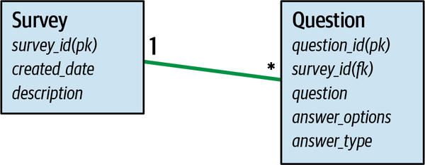
Figure 6-34. Tables and relationships in the sysops survey data domain
An example of the data contained in each table is shown Figure 6-35, where the Question table contains the question, the answer options, and the data type for the answer.
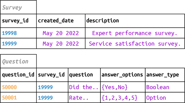
Figure 6-35. Relational data in tables for survey and question in the survey data domain
“So, essentially we have two options for modeling the survey questions in a document database,” said Devon. “A single aggregate document or one that is split.”
“How to we know which one to use?” asked Skyler, happy that the development teams were now finally working with the database teams to arrive at a unified solution.
“I know,” said Addison, “let’s model both so we can visually see the trade-offs with each approach.”
Devon showed the team that with the single aggregate option, as shown in Figure 6-36, with the corresponding source code listing in Example 6-3, both the survey data and all related question data were stored as one document. Therefore, the entire customer survey could be retrieved from the database by using a single get operation, making it easy for Skyler and others on the development team to work with the data.
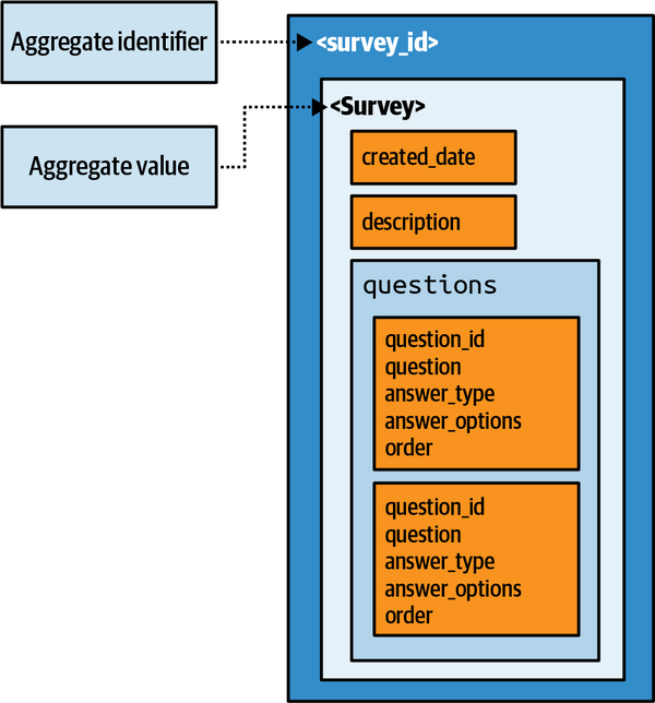
Figure 6-36. Survey model with single aggregate
Example 6-3. JSON document for single aggregate design with children embedded
#Surveyaggregatewithembeddedquestions{"survey_id":"19999","created_date":"Dec 28 2021","description":"Survey to gauge customer...","questions":[{"question_id":"50001","question":"Rate the expert","answer_type":"Option","answer_options":"1,2,3,4,5","order":"2"},{"question_id":"50000","question":"Did the expert fix the problem?","answer_type":"Boolean","answer_options":"Yes,No","order":"1"}]}
“I really like that approach,” said Skyler. “Essentially, I wouldn’t have to worry so much about aggregating things myself in the user interface, meaning I could simply render the document I retrieve on the web page.”
“Yeah,” said Devon, “but it would require additional work on the database side as questions would be replicated in each survey document. You know, the whole reuse argument. Here, let me show you the other approach.”
Skyler explained that another way to think about aggregates was to split the survey and question model so that the questions could be operated on in an independent fashion, as shown in Figure 6-37, with the corresponding source code listing in Example 6-4. This would allow the same question to be used in multiple surveys, but would be harder to render and retrieve than the single aggregate.
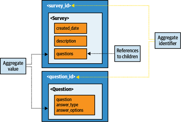
Figure 6-37. Survey model with multiple aggregates with references
Example 6-4. JSON document with aggregates split and parent document showing references to children
#SurveyaggregatewithreferencestoQuestions{"survey_id":"19999","created_date":"Dec 28","description":"Survey to gauge customer...","questions":[{"question_id":"50001","order":"2"},{"question_id":"50000","order":"1"}]}#Questionaggregate{"question_id":"50001","question":"Rate the expert","answer_type":"Option","answer_options":"1,2,3,4,5"}{"question_id":"50000","question":"Did the expert fix the problem?","answer_type":"Boolean","answer_options":"Yes,No"}
Because most of the complexity and change issues were in the user interface, Skyler liked the single aggregate model better. Devon liked the multiple aggregate to avoid duplication of question data in each survey. However, Addison pointed out that there were only five survey types (one for each product category), and that most of the changes involved adding or removing questions. The team discussed the trade-offs, and all agreed that they were willing to trade off some duplication of question data for the ease of changes and rendering on the user interface side. Because of the difficulty of this decision and the structural nature of changing the data, Addison created an ADR to record the justifications of this decision:
ADR: Use of Document Database for Customer Survey
Context
Customers receive a survey after the work has been completed by the customer, which is rendered on a web page for the customer to fill out and submit. The customer receives one of five survey types based on the type of electronic product fixed or installed. The survey is currently stored in a relational database, but the team wants to migrate the survey to a document database using JSON.Decision
We will use a document database for the customer survey.The Marketing Department requires more flexibility and timeliness for changes to the customer surveys. Moving to a document database would not only provide better flexibility, but also better timeliness for changes needed to the customer surveys.
Using a document database would simplify the customer survey user interface and better facilitate changes to the surveys.
Consequences
Since we will be using a single aggregate, multiple documents would need to be changed when a common survey question is updated, added, or removed.Survey functionality will need to be shut down during the data migration from the relational database to the document database.
Chapter 7. Service Granularity
Thursday, October 14, 13:33
As the migration effort got underway, both Addison and Austen
“I’m still not sure what to do with the core ticketing functionality,” said Addison. “I can’t decide whether ticket creation, completion, expert assignment, and expert routing should be one, two, three, or even four services. Taylen is insisting on making everything fine-grained, but I’m not sure that’s the right approach.”
“Me neither,” said Austen. “And I’ve got my own issues trying to figure out if the customer registration, profile management, and billing functionality should even be broken apart. And on top of all that, I’ve got another game this evening.”
“You’ve always got a game to go to,” said Addison. “Speaking of customer functionality, did you ever figure out if the customer login functionality is going to be a separate service?”
“No,” said Austen, “I’m still working on that as well. Skyler says it should be separate, but won’t give me a reason other than to say it’s separate functionality.”
“This is hard stuff,” said Addison. “Do you think Logan can shed any light on this?”
“Good idea,” said Austen, “This seat-of-the-pants analysis is really slowing things down.”
Addison and Austen invited Taylen, the Sysops Squad tech lead, to the meeting with Logan so that all of them could be on the same page with regard to the service granularity issues they were facing.
“I’m telling you,” said Taylen, “we need to break up the domain services into smaller services. They are simply too coarse-grained for microservices. From what I remember, micro means small. We are, after all, moving to microservices. What Addison and Austen are suggesting simply doesn’t fit with the microservices model.”
“Not every portion of an application has to be microservices,” said Logan. “That’s one of the biggest pitfalls of the microservices architecture style.”
“If that’s the case, then how do you determine what services should and shouldn’t be broken apart?” asked Taylen.
“Single-responsibility principle,” answered Taylen. “Look it up. That’s what microservices is based on.”
“I know what the single-responsibility principle is,” said Logan. “And I also know how subjective it can be. Let’s take our customer notification service as an example. We can notify our customers through SMS, email, and we even send out postal letters. So tell me everyone, one service or three services?”
“Three,” immediately answered Taylen. “Each notification method is its own thing. That’s what microservices is all about.”
“One,” answered Addison. “Notification itself is clearly a single responsibility.”
“I’m not sure,” answered Austen. “I can see it both ways. Should we just toss a coin?”
“This is exactly why we need help,” sighed Addison.
“The key to getting service granularity right,” said Logan, “is to remove opinion and gut feeling, and use granularity disintegrators and integrators to objectively analyze the trade-offs and form solid justifications for whether or not to break apart a service.”
“What are granularity disintegrators and integrators?” asked Austen.
“Let me show you,” said Logan.
- Modularity
-
Constructed with standardized units or dimensions for flexibility and variety in use.
- Granularity
-
Consisting of or appearing to consist of one of numerous particles forming a larger unit.
Determining the right level of granularity—the size of a service—is one of the many hard parts of software architecture that architects and development teams continually struggle with. Granularity is not defined by the number of classes or lines of code in a service, but rather what the service does—hence why it is so hard to get service granularity right.
Architects can leverage metrics to monitor and measure various aspects of a service to determine the appropriate level of service granularity.
Another metric to determine service granularity is to measure and track the number of public interfaces or operations exposed by a service. Granted, while there is still a bit of subjectiveness and variability with these two metrics, it’s the closest thing we’ve come up with so far to objectively measure and assess service granularity.
Two opposing forces for service granularity are granularity disintegrators and granularity integrators.
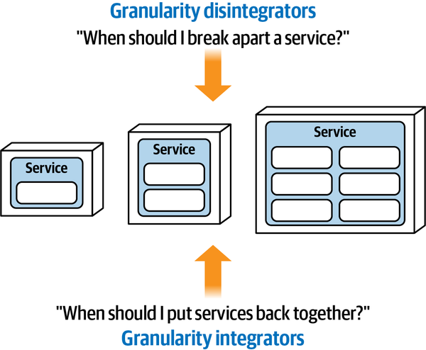
Figure 7-1. Service granularity depends on a balance of disintegrators and integrators
Granularity Disintegrators
Granularity disintegrators provide guidance and justification for when to break a service into smaller pieces.
- Service scope and function
-
Is the service doing too many unrelated things?
- Code volatility
-
Are changes isolated to only one part of the service?
- Scalability and throughput
-
Do parts of the service need to scale differently?
- Fault tolerance
-
Are there errors that cause critical functions to fail within the service?
- Security
-
Do some parts of the service need higher security levels than others?
- Extensibility
-
Is the service always expanding to add new contexts?
The following sections detail each of these granularity disintegration drivers.
Service Scope and Function
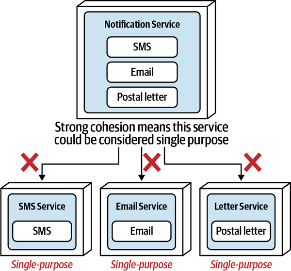
Figure 7-2. A service with relatively strong cohesion is not a good candidate for disintegration based on functionality alone
Now consider a single service that manages the customer profile information, customer preferences, and also customer comments made on the website. Unlike the previous Notification Service example, this service has relatively weak cohesion because these three functions relate to a broader scope—customer. This service is possibly doing too much, and hence should probably be broken into three separate services, as illustrated in Figure 7-3.
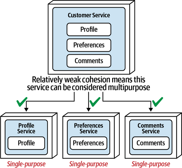
Figure 7-3. A service with relatively weak cohesion is a good candidate for disintegration
This granularity disintegrator is related to the
Within the microservices architecture style, a microservice is
Code Volatility
Code volatility--the rate at which the source code changes—is another
-
SMS notification functionality rate of change: every six months (avg)
-
Email notification functionality rate of change: every six months (avg)
-
Postal letter notification functionality rate of change: weekly (avg)
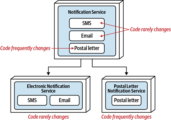
Figure 7-4. An area of high code change in a service is a good candidate for disintegration
Scalability and Throughput
Another driver for breaking up a service into separate smaller ones is scalability and throughput.
-
SMS notification: 220,000/minute
-
Email notification: 500/minute
-
Postal letter notification: 1/minute
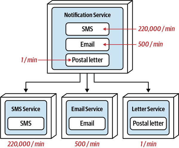
Figure 7-5. Differing scalability and throughput needs is a good disintegration driver
Fault Tolerance
Fault tolerance describes the ability of an application or functionality
Separating this single consolidated Notification Service into three separate services provides a level of fault tolerance for the domain of customer notification. Now, a fatal error in the functionality of the email service doesn’t impact SMS or postal letters.
Notice in this example that the Notification Service is split into three separate services (SMS, Email, and Postal Letter), even though email functionality is the only issue with regard to frequent crashes (the other two are very stable). Since email functionality is the only issue, why not combine the SMS and postal letter functionality into a single service?
Consider the code volatility example from the prior section. In this case Postal Letter changes constantly, whereas the other two (SMS and Email) do not. Splitting this service into only two services made sense because Postal Letter was the offending functionality, but Email and SMS are related—they both have to do with electronically notifying the customer. Now consider the fault-tolerance example. What do SMS notification and Postal Letter notification have in common other than a notification means to the customer? What would be an appropriate self-descriptive name of that combined service?
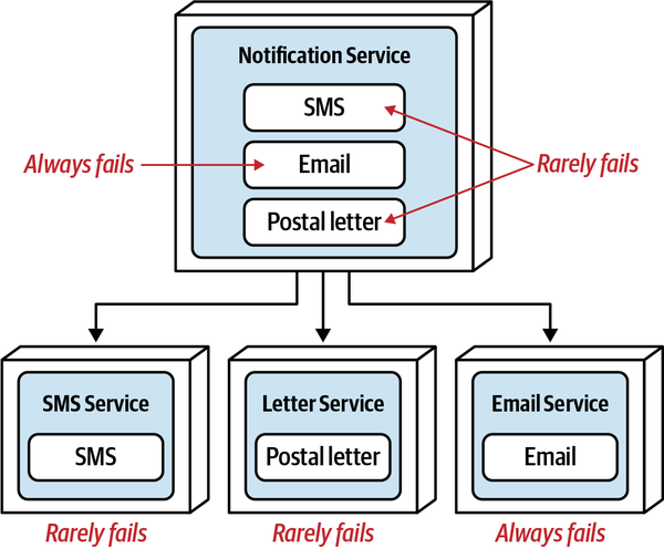
Figure 7-6. Fault tolerance and service availability are good disintegration drivers
Moving the email functionality to a separate service disrupts the overall domain cohesion
-
Notification Service → Email Service, Other Notification Service (poor name)
-
Notification Service → Email Service, Non-Email Service (poor name)
-
Notification Service → Email Service, SMS-Letter Service (poor name)
-
Notification Service → Email Service, SMS Service, Letter Service (good names)
In this example, only the last disintegration makes sense, particularly considering the addition of another social media notification—where would that go? Whenever breaking apart a service, regardless of the disintegration driver, always check to see if strong cohesion can be formed with the “leftover” functionality.
Security
Consider the example illustrated in Figure 7-7 that describes a Customer Profile Service containing two main functions: customer profile maintenance for adding, changing, or deleting basic profile information (name, address, and so on); and customer credit card maintenance for adding, removing, and updating credit card information.
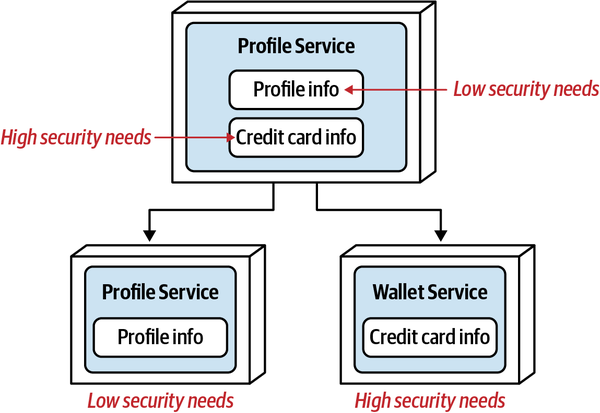
Figure 7-7. Security and data access are good disintegration drivers
While the credit card data may be protected, access to that data is at risk because the credit card functionality is joined together with the basic customer profile functionality. Although the API entry points into the consolidated customer profile service may differ, nevertheless there is risk that someone entering into the service to retrieve the customer name might also have access to credit card functionality. By breaking this service into two separate services, access to the functionality used to maintain credit card information can be made more secure because the set of credit card operations is going into only a single-purpose service.
Extensibility
Another primary driver for granularity disintegration is
These additional payment methods could certainly be added to a single consolidated payment service. However, every time a new payment method is added, the entire payment service would need to be tested (including other payment types), and the functionality for all other payment methods unnecessarily redeployed into production. Thus, with the single consolidated payment service, the testing scope is increased and deployment risk is higher, making it more difficult to add additional payment types.
Now that the single payment service is broken into separate services by payment methods, adding another payment method (such as reward points) is only a matter of developing, testing, and deploying a single service separate from the others. As a result, development is faster, testing scope is reduced, and deployment risk is lower.
Our advice is to apply this driver only if it is known ahead of time that additional consolidated contextual functionality is planned, desired, or part of the normal domain. For example, with notification, it is doubtful the means of notification would continually expand beyond the basic notification means (SMS, email, or letter). However, with payment processing, it is highly likely that additional payment types would be added in the future, and therefore separate services for each payment type would be warranted. Since it is often difficult to sometimes “guess” whether (and when) contextual functionality might expand (such as additional payment methods), our advice is to wait on this driver as a primary means of justifying a granularly disintegration until a pattern can be established or confirmation of continued extensibility can be confirmed.
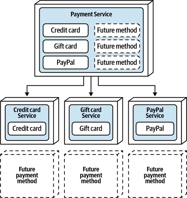
Figure 7-8. Planned extensibility is a good disintegration driver
Granularity Integrators
Whereas granularity disintegrators provide guidance and
- Database transactions
-
Is an ACID transaction required between separate services?
- Workflow and choreography
-
Do services need to talk to one another? Shared code: Do services need to share codeamong one another? Database relationships: Although a service can be broken apart, can the data it uses be broken apart as well?
The following sections detail each of these granularity integration drivers.
Database Transactions
Notice that having two separate services provides a good level of security access control to password information since access is at a service level rather than at a request level. Access to operations such as changing a password, resetting a password, and accessing a customer’s password for sign-in can all be restricted to a single service (and hence the access can be restricted to that single service). However, while this may be a good disintegration driver, consider the operation of registering a new customer, as illustrated in Figure 7-10.
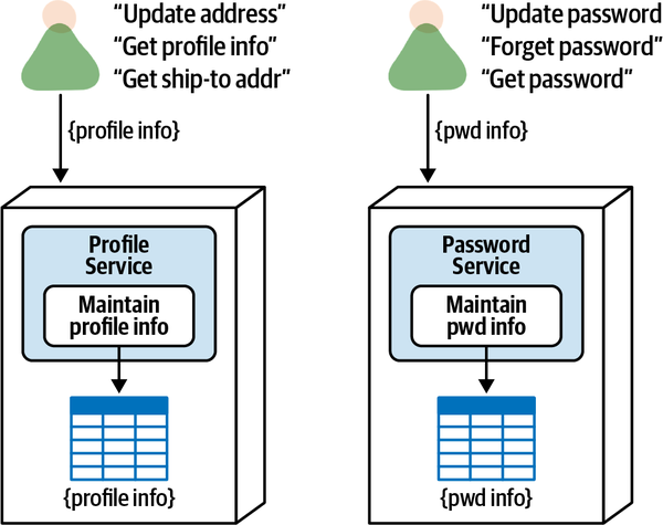
Figure 7-9. Separate services with atomic operations have better security access control
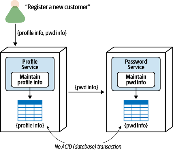
Figure 7-10. Separate services with combined operations do not support database (ACID) transactions
When registering a new customer, both profile and encrypted password information is passed into the Profile Service from a user interface screen. The Profile Service inserts the profile information into its corresponding database table, commits that work, and then passes the encrypted password information to the Password Service, which in turn inserts the password information into its corresponding database table and commits its own work.
While separating the services provides better security access control to the password information, the trade-off is that there is no ACID transaction for actions such as registering a new customer or unsubscribing (deleting) a customer from the system. If the password service fails during either of these operations, data is left in an inconsistent state, resulting in complex error handling (which is also error prone) to reverse the original profile insert or take other corrective action (see “Transactional Saga Patterns” for the details of eventual consistency and error handling within distributed transactions). Thus, if having a single-unit-of-work ACID transaction is required from a business perspective, these services should be consolidated into a single service, as illustrated in Figure 7-11.
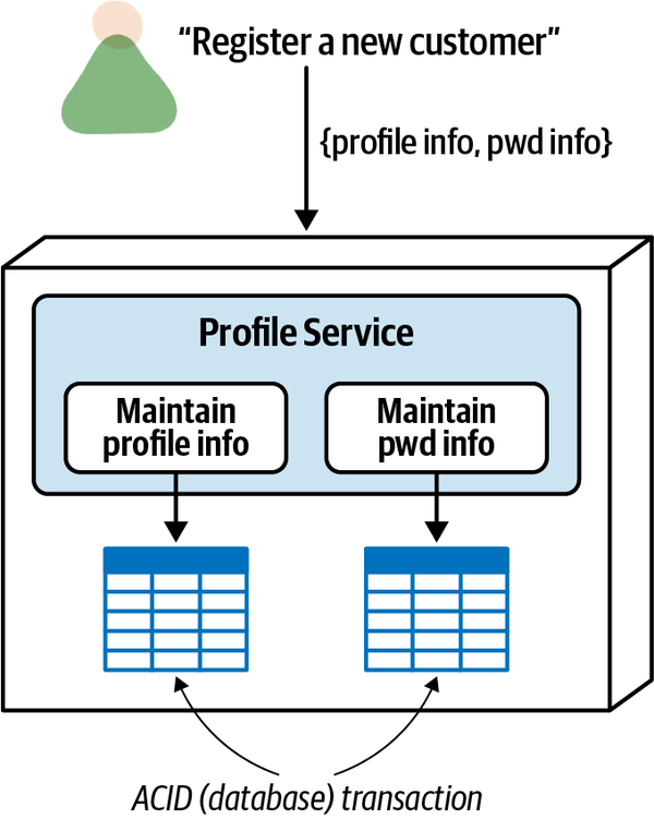
Figure 7-11. A single service supports database (ACID) transactions
Workflow and Choreography
Another common granularity integrator is workflow and
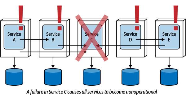
Figure 7-12. Too much workflow impacts fault tolerance
Interestingly enough, fault tolerance is one of the granularity disintegration drivers from the previous section—yet when those services need to talk to one another, nothing is really gained from a fault-tolerance perspective. When breaking apart services, always check to see if the functionalities are tightly coupled and dependent on one another. If it is, then overall fault tolerance from a business request standpoint won’t be achieved, and it might be best to consider keeping the services together.
Overall performance and responsiveness is another driver for granularity integration (putting services back together). Consider the scenario in Figure 7-13: a large customer service is split into five separate services (services A through E). While each of these services has its own collection of cohesive atomic requests, retrieving all of the customer information collectively from a single API request into a single user interface screen involves five separate hops when using choreography (see Chapter 11 for an alternative solution to this problem using orchestration). Assuming 300 ms in network and security latency per request, this single request would incur an additional 1500 ms just in latency alone! Consolidating all of these services into a single service would remove the latency, therefore increasing overall performance and responsiveness.
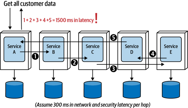
Figure 7-13. Too much workflow impacts overall performance and responsiveness
In terms of overall performance, the trade-off for this integration driver is balancing the need to break apart a service with the corresponding performance loss if those services need to communicate with one another. A good rule of thumb is to take into consideration the number of requests that require multiple services to communicate with one another, also taking into account the criticality of those requests requiring interservice communication. For example, if 30% of the requests require a workflow between services to complete the request and 70% are purely atomic (dedicated to only one service without the need for any additional communication), then it might be OK to keep the services separate. However, if the percentages are reversed, then consider putting them back together again. This assumes, of course, that overall performance matters. There’s more leeway in the case of backend functionality where an end user isn’t waiting for the request to complete.
The other performance consideration is with regard to the criticality of the request requiring workflow. Consider the previous example, where 30% of the requests require a workflow between services to complete the request, and 70% are purely atomic. If a critical request that requires extremely fast response time is part of that 30%, then it might be wise to put the services back together, even though 70% of the requests are purely atomic.
Overall reliability and data integrity are also impacted with increased service communication. Consider the example in Figure 7-14: customer information is separated into five separate customer services. In this case, adding a new customer to the system involves the coordination of all five customer services. However, as explained in a previous section, each of these services has its own database transaction. Notice in Figure 7-14 that services A, B, and C have all committed part of the customer data, but Service D fails.
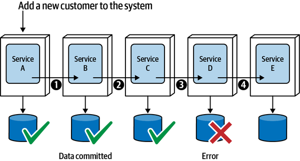
Figure 7-14. Too much workflow impacts reliability and data integrity
This creates a data consistency and data integrity issue because part of the customer data has already been committed, and may have already been acted upon through a retrieval of that information from another process or even a message sent out from one of those services broadcasting an action based on that data. In either case, that data would either have to be rolled back through compensating transactions or marked with a specific state to know where the transaction left off in order to restart it. This is very messy situation, one we describe in detail in “Transactional Saga Patterns”. If data integrity and data consistency are important or critical to an operation, it might be wise to consider putting those services back together.
Shared Code
Consider the set of five services shown in Figure 7-15. While there may have been a good disintegrator driver for breaking apart these services, they all share a common codebase of domain functionality (as opposed to common utilities or infrastructure functionality). If a change occurs in the shared library,
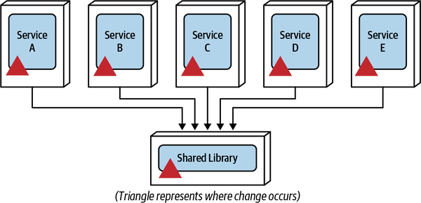
Figure 7-15. A change in shared code requires a coordinated change to all services
Not all uses of shared code drive granularity integration. For example, infrastructure-related cross-cutting functionality such as logging, auditing, authentication, authorization, and monitoring that all services use is not a good driver for putting services back together or even moving back to a monolithic architecture. Some of the guidelines for considering shared code as a granularity integrator are as follows:
- Specific shared domain functionality
-
Shared domain functionality is shared code that contains business logic
(as opposed to infrastructure-related cross-cutting functionality). Our recommendation is to consider this factor as a possible granularity integrator if the percentage of shared domain code is relatively high. For example, suppose the common (shared) code for a group of customer-related functionality (profile maintenance, preference maintenance, and adding or removing comments) makes up over 40% of the collective codebase. Breaking up the collective functionality into separate services would mean that almost half of the source code is in a shared library used only by those three services. In this example it might be wise to consider keeping the collective customer-related functionality in a single consolidated service along with the shared code (particularly if the shared code changes frequently, as discussed next). - Frequent shared code changes
- Regardless of the size of the shared library, frequent changes to shared functionality require frequent coordinated changes to the services using that shared domain functionality.While versioning can sometimes be used to help mitigate coordinated changes, eventually services using that shared functionality will need to adopt the latest version. If the shared code changes frequently, it might be wise to consider consolidating the services using that shared code to help mitigate the complex change coordination of multiple deployment units.
- Defects that cannot be versioned
- While versioning can help mitigate coordinated changes and allow for backward compatibility and agility (the ability to respond quickly to change), at times certain business functionality must be applied to all services at the same time (such as a defect or a change in business rules). If this happens frequently, it might be time to consider putting services back together to simplify the changes.
Data Relationships
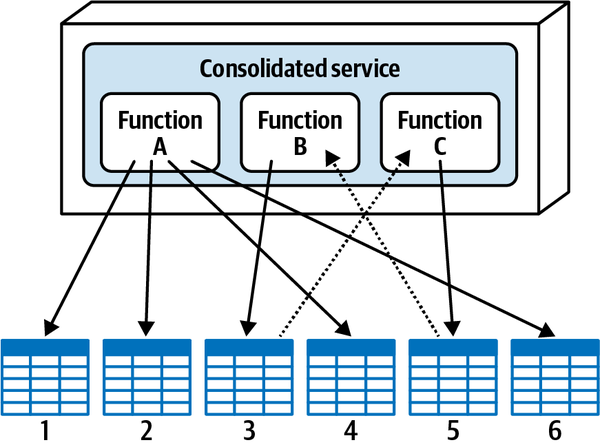
Figure 7-16. The database table relationships of a consolidated service
| Function | Table 1 | Table 2 | Table 3 | Table 4 | Table 5 | Table 6 |
|---|---|---|---|---|---|---|
A | owner | owner | owner | owner | ||
B | owner | access | ||||
C | access | owner |
Assume that based on some of the disintegration drivers outlined in the prior section,
Notice at the top of Figure 7-17 that Service A owns tables 1, 2, 4, and 6 as part of its bounded context; Service B owns table 3; and Service C owns table 5. However, notice in the diagram that every operation in Service B requires access to data in table 5 (owned by Service C), and every operation in Service C requires access to data in table 3 (owned by Service B). Because of the bounded context, Service B cannot simply reach out and directly query table 5, nor can Service C directly query table 3.
To better understand the bounded context and why Service C cannot simply access table 3,
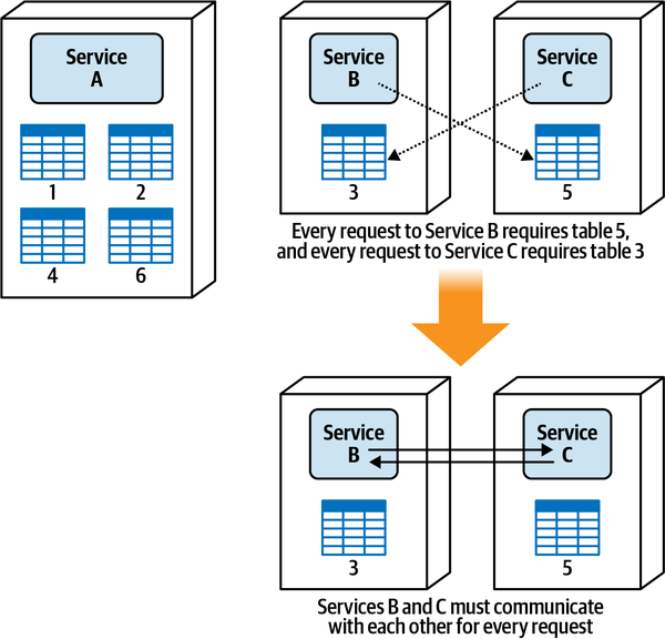
Figure 7-17. Database table relationships impact service granularity
Based on the dependency of the data between services B and C, it would be wise to consolidate those services into a single service to avoid the latency, fault tolerance, and scalability issues associated with the interservice communication between these services, demonstrating that relationships between tables can influence service granularity. We’ve saved this granularity integration driver for last because it is the one granularity integration driver with the fewest number of trade-offs. While occasionally a migration from a monolithic system requires a refactoring of the way data is organized, in most cases it isn’t feasible to reorganize database table entity relationships for the sake of breaking apart a service. We dive into the details about breaking apart data in Chapter 6.
Finding the Right Balance
| Disintegrator driver | Reason for applying driver |
|---|---|
Service scope | Single-purpose services with tight cohesion |
Code volatility | Agility (reduced testing scope and deployment risk) |
Scalability | Lower costs and faster responsiveness |
Fault tolerance | Better overall uptime |
Security access | Better security access control to certain functions |
Extensibility | Agility (ease of adding new functionality) |
| Integrator driver | Reason for applying driver |
|---|---|
Database transactions | Data integrity and consistency |
Workflow | Fault tolerance, performance, and reliability |
Shared code | Maintainability |
Data relationships | Data integrity and correctness |
Architects can use the drivers in these tables to form trade-off statements that can then be discussed and resolved by collaborating with a product owner or business sponsor.
Example 1:
Architect: “We want to break apart our service to isolate frequent code changes, but in doing so we won’t be able to maintain a database transaction. Which is more important based on our business needs—better overall agility (maintainability, testability, and deployability), which translates to faster time-to-market, or stronger data integrity and consistency?”
Project Sponsor: “Based on our business needs, I’d rather sacrifice a little bit slower time-to-market to have better data integrity and consistency, so let’s leave it as a single service for right now.”
Example 2:
Architect: “We need to keep the service together to support a database transaction between two operations to ensure data consistency, but that means sensitive functionality in the combined single service will be less secure. Which is more important based on our business needs—better data consistency or better security?”
Project Sponsor: “Our CIO has been through some rough situations with regard to security and protecting sensitive data, and it’s on the forefront of their mind and part of almost every discussion. In this case, it’s more important to secure sensitive data, so let’s keep the services separate and work out how we can mitigate some of the issues with data consistency.”
Example 3:
Architect: “We need to break apart our payment service to provide better extensibility for adding new payment methods, but that means we will have increased workflow that will impact the responsiveness when multiple payment types are used for an order (which happens frequently). Which is more important based on our business needs—better extensibility within the payment processing, hence better agility and overall time-to-market, or better responsiveness for making a payment?”
Project Sponsor: “Given that I see us adding only two, maybe three more payment types over the next couple of years, I’d rather have us focus on the overall responsiveness since the customer must wait for payment processing to be complete before the order ID is issued.”
Sysops Squad Saga: Ticket Assignment Granularity
Monday, October 25 11:08
Once a trouble ticket has been created by a customer and accepted by the system,
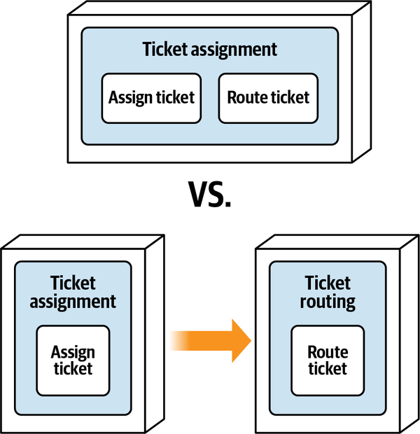
Figure 7-18. Options for ticket assignment and routing
“So you see,” said Taylen, “the ticket assignment algorithms are very complex, and therefore should be isolated from the ticket routing functionality. That way, when those algorithms change, I don’t have to worry about all of the routing functionality.”
“Yes, but how much change is there to those assignment algorithms?” asked Addison. “And how much change do we anticipate in the future?”
“I apply changes to those algorithms at least two to three times a month. I read about volatility-based decomposition, and this situation fits it perfectly,” said Taylen.
“But if we separated the assignment and routing functionality into two services, there would need to be constant communication between them,” said Skyler. “Furthermore, assignment and routing are really one function, not two.”
“No,” said Taylen, “they are two separate functions.”
“Hold on,” said Addison. “I see what Skyler means. Think about it a minute. Once an expert is found that is available within a certain period of time, the ticket is immediately routed to that expert. If no expert is available, the ticket goes back in the queue and waits until an expert can be found.”
“Yes, that’s right,” said Taylen.
“See,” said Skyler, “you cannot make a ticket assignment without routing it to the expert. So the two functions are one.”
“No, no, no,” said Taylen. “You don’t understand. If an expert is seen to be available within a certain amount of time, then that expert is assigned. Period. Routing is just a transport thing.”
“What happens in the current functionality if a ticket can’t be routed to the expert?” asked Addison.
“Then another expert is selected,” said Taylen.
“OK, so think about it a minute, Taylen,” said Addison. “If assignment and routing are two separate services, then the routing service would have to then communicate back to the assignment service, letting it know that the expert cannot be located and to pick another one. That’s a lot of coordination between the two services.”
“Yes, but they are still two separate functions, not one as Skyler is suggesting,” said Taylen.
“I have an idea,” said Addison. “Can we all agree that the assignment and routing are two separate activities, but are tightly bound synchronously to each other? Meaning, one function cannot exist without the other?”
“Yes,” both Taylen and Skyler replied.
“In that case,” said Addison, “let’s analyze the trade-offs. Which is more important—isolating the assignment functionality for change control purposes, or combining assignment and routing into a single service for better performance, error handling, and workflow control?”
“Well,” said Taylen, “when you put it that way, obviously the single service. But I still want to isolate the assignment code.”
“OK,” said Addison, “in that case, how about we make three distinct architectural components in the single service. We can delineate assignment, routing, and shared code with separate namespaces in the code. Would that help?”
“Yeah,” said Taylen, “that would work. OK, you both win. Let’s go with a single service then.”
“Taylen,” said Addison, “it’s not about winning, it’s about analyzing the trade-offs to arrive at the most appropriate solution; that’s all.”
With everyone agreeing to a single service for assignment and routing, Addison wrote the following architecture decision record (ADR) for this decision:
ADR: Consolidated Service for Ticket Assignment and Routing
Context
Once a ticket is created and accepted by the system, it must be assigned to an expert and then routed to that expert’s mobile device. This can be done through a single consolidated ticket assignment service or separate services for ticket assignment and ticket routing.Decision
We will create a single consolidated ticket assignment service for the assignment and routing functions of the ticket.Tickets are immediately routed to the Sysops Squad expert once they are assigned, so these two operations are tightly bound and dependent each other.
Both functions must scale the same, so there are no throughput differences between these services,
nor isback-pressure needed between these functions.
Since both functions are fully dependent on each other, fault tolerance is not a driver for breaking these functions apart.
Making these functions separate services would require workflow between them, resulting in performance, fault tolerance, and possible reliability issues.
Consequences
Changes to the assignment algorithm (which occur on a regular basis) and changes to the routing mechanism (infrequent change) would require testing and deployment of both functions, resulting in increased testing scope and deployment risk.
Sysops Squad Saga: Customer Registration Granularity
Friday January 14, 13:15
Customers must register with the system to gain access to the Sysops Squad support plan.
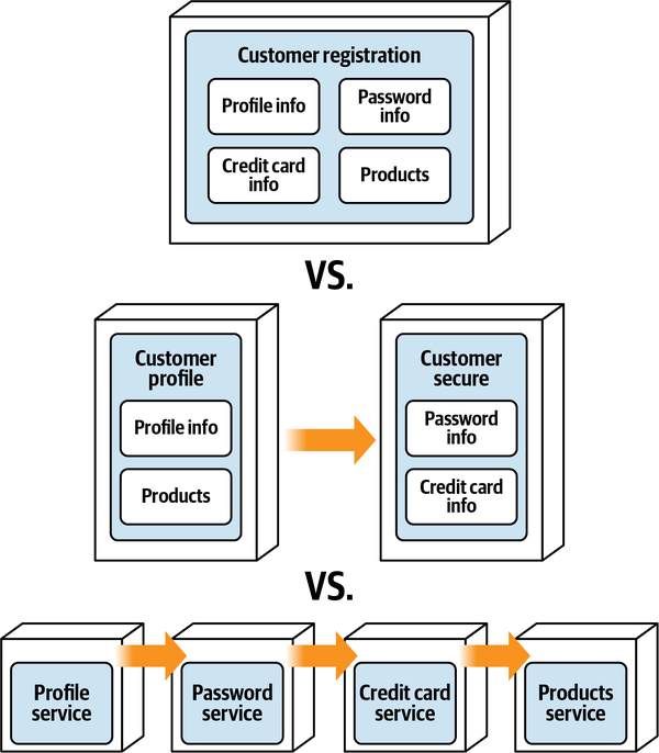
Figure 7-19. Options for customer registration
Because Addison was busy with the core ticketing functionality, the development team asked for Austen’s help in resolving this granularity issue. Anticipating this will not be an easy decision, particularly since it involved security, Austen scheduled a meeting with Parker, (the product owner), and Sam, the Penultimate Electronics security expert to discuss these options.
“OK, so what can we do for you?” asked Parker.
“Well,” said Austen, “we are struggling with how many services to create for registering customers and maintaining customer-related information, You see, there are four main pieces of data we are dealing with here: profile info, credit card info, password info, and purchased product info.”
“Whoa, hold on now,” interrupted Sam. “You know that credit card and password information must be secure, right?”
“Of course we know it has to be secure,” said Austen. “What we’re struggling with is the fact that there’s a single customer registration API to the backend, so if we have separate services they all have to be coordinated together when registering a customer, which would require a distributed transaction.”
“What do you mean by that?” asked Parker.
“Well,” said Austen, “we wouldn’t be able to synchronize all of the data together as one atomic unit of work.”
“That’s not an option,” said Parker. “All of the customer information is either saved in the database, or it’s not. Let me put it another way. We absolutely cannot have the situation where we have a customer record without a corresponding credit card or password record. Ever.”
“OK, but what about securing the credit card and password information?” asked Sam. “Seems to me, having separate services would allow much better security control access to that type of sensitive information.”
“I think I may have an idea.” said Austen. “The credit card information is tokenized in the database, right?”
“Tokenized and encrypted,” said Sam.
“Great. And the password information?” asked Austen.
“The same,” said Sam.
“OK,” said Austen, “so it seems to me that what we really need to focus on here is controlling access to the password and credit card information separate from the other customer-related requests—you know, like getting and updating profile information, and so on.”
“I think I see where you are coming from with your problem,” said Parker. “You’re telling me that if you separate all of this functionality into separate services, you can better secure access to sensitive data, but you cannot guarantee my all-or-nothing requirement. Am I right?”
“Exactly. That’s the trade-off,” said Austen.
“Hold on,” said Sam. “Are you using the Tortoise security libraries to secure the API calls?”
“Yes. We use those libraries not only at the API layer, but also within each service to control access through the service mesh. So essentially it’s a double-check,” said Austen.
“Hmmm,” said Sam. “OK, I’m good with a single service providing you use the Tortoise security framework.”
“Me too, providing we can still have the all-or-nothing customer registration process,” said Parker.
“Then I think we are all in agreement that the all-or-nothing customer registration is an absolute requirement and we will maintain multilevel security access using Tortoise,” said Austen.
“Agreed,” said Parker.
“Agreed,” said Sam.
Parker noticed how Austen handled the meeting by facilitating the conversation rather than controlling it. This was an important lesson as an architect in identifying, understanding, and negotiating trade-offs.
Based on the conversation with Parker and Sam, Austen made the decision that customer-related functionality would be managed through a single consolidated domain service (rather than separately deployed services) and wrote the following ADR for this decision:
ADR: Consolidated Service for Customer-Related Functionality
Context
Customers must register with the system to gain access to the Sysops Squad support plan. During registration, customers must provide profile information, credit card information, password information, and products purchased. This can be done through a single consolidated customer service, a separate service for each of these functions, or a separate service for sensitive and nonsensitive data.Decision
We will create a single consolidated customer service for profile, credit card, password, and products supported.Customer registration and unsubscribe functionality requires a single atomic unit of work. A single service would support ACID transactions to meet this requirement, whereas separate services would not.
Use of the Tortoise security libraries in the API layer and the service mesh will mitigate security access risk to sensitive information.
Consequences
We will require the Tortoise security library to ensure security access in both the API gateway and the service mesh.Because it’s a single service, changes to source code for profile info, credit card, password, or products purchased will increase testing scope and increase deployment risk.
The combined functionality (profile, credit card, password, and products purchased) will have to scale as one unit.
The trade-off discussed in a meeting with the product owner and security expert is transactionality versus security. Breaking the customer functionality into separate services provides better security access, but doesn’t support the “all-or-nothing” database transaction required for customer registration or unsubscribing. However, the security concerns are mitigated through the use the custom Tortoise security library.
Part II. Putting Things Back Together
Attempting to divide a cohesive module would only result in increased coupling and decreased readability.
Larry Constantine
Once a system is broken apart, architects often find it necessary to stitch it back together to make it work as one cohesive unit. As Larry Constantine so eloquently infers in the preceding quote, it’s not quite as easy as it sounds, with lots of trade-offs involved when breaking things apart.
In this second part of this book, we discuss various techniques for overcoming some of the hard challenges associated with distributed architectures, including managing service communication, contracts, distributed workflows, distributed transactions, data ownership, data access, and analytical data.
Chapter 8. Reuse Patterns
Wednesday, February 2, 15:15
As the development team members worked on breaking apart the domain services,
“What in the world are you doing?” asked Taylen.
“I’m moving all of the shared code to a new workspace so we can create a shared DLL from it,” replied Skyler.
“A single shared DLL?”
“That’s what I was planning,” said Skyler. “Most of the services will need this stuff anyway, so I’m going to create a single DLL that all the services can use.”
“That’s the worst idea I’ve ever heard,” said Taylen. “Everyone knows you should have multiple shared libraries in a distributed architecture!”
“Not in my opinion,” said Sydney. “Seems to me it’s much easier to manage a single shared library DLL rather than dozens of them.”
“Given that I’m the tech lead for this application, I want you to split that functionality into separate shared libraries.”
“OK, OK, I suppose I can move the all of the authorization into its own separate DLL if that would make you happy,” said Skyler.
“What?” said Taylen. “The authorization code has to be a shared service, you know——not in a shared library."”
“No,” said Skyler. “That code should be in a shared DLL.”
“What’s all the shouting about over there?” asked Addison.
“Taylen wants the authorization functionality to be in a shared service. That’s just crazy. I think it should go in the common shared DLL,” said Skyler.
“No way,” said Taylen. “It’s got to be in its own separate shared service.”
“And,” said Skyler, “Taylen is insisting on having multiple shared libraries for the shared functionality rather than a single shared library.”
“Tell you what,” said Addison. “Let’s go over the trade-offs of shared library granularity, and also go over the trade-offs between a shared library and a shared service to see if we can resolve these issues in a more reasonable and thoughtful manner.”
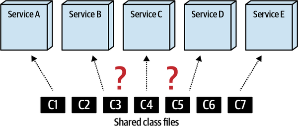
Figure 8-1. Code reuse is a hard part of distributed architecture
Frequently within highly distributed architectures like microservices and serverless environments, phrases like “reuse is abuse!” and “share nothing!” are touted by architects in an attempt to reduce the amount of shared code within these types of architectures. Architects in these environments have even been found to offer countering advice to the famous DRY principle (Don’t repeat yourself) by using an opposing acronym called WET (Write every time or Write everything twice).
While developers should try to limit the amount of code reuse within distributed architectures, it is nevertheless a fact of life in software development and must be addressed, particularly in distributed architectures. In this chapter, we introduce several techniques for managing code reuse within a distributed architecture, including replicating code, shared libraries, shared services, and sidecars within a service mesh. For each of these options, we also discuss the pros, cons, and trade-offs of each approach.
Code Replication
In code replication, shared code is copied into each service
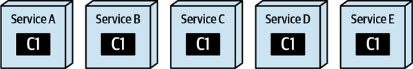
Figure 8-2. With replication, shared functionality is copied into each service
While code replication isn’t used much today, it nevertheless is still a valid technique for addressing code reuse across multiple distributed services. This technique should be approached with extreme caution for the obvious reason that if a bug is found in the code or an important change to the code is needed, it would be very difficult and time-consuming to update all services containing the replicated code.
At times, however, this technique can prove useful, particularly for highly static one-off code that most (or all) services need. For example, consider the Java code in Example 8-1 and the corresponding C# code in Example 8-2 that identifies the class in the service that represents the service entry point (usually the restful API class within a service).
Example 8-1. Source code defining a service entry point annotation (Java)
@Retention(RetentionPolicy.RUNTIME)@Target(ElementType.TYPE)public@interfaceServiceEntrypoint{}/* Usage:@ServiceEntrypointpublic class PaymentServiceAPI {...}*/
Example 8-2. Source code defining a service entry point attribute (C#)
[AttributeUsage(AttributeTargets.Class)]classServiceEntrypoint:Attribute{}/* Usage:[ServiceEntrypoint]class PaymentServiceAPI {...}*/
Note that the source code in Example 8-1 actually contains no functionality whatsoever.
This kind of source code makes a good candidate for replication because it’s static and doesn’t contain any bugs (and most likely will not in the future). If this were a unique one-off class, it might be worth copying it into each service code repository rather than creating a shared library for it. That said, we generally encourage investigating the other code-sharing techniques presented in this chapter before opting for the code replication technique.
While the replication technique preserves the bounded context, it does make it difficult to apply changes if the code ever does need to be modified. Table 8-1 lists the various trade-offs associated with this technique.
When to Use
The replication technique is a good approach when developers have simple static code (like annotations, attributes, simple common utilities, and so on) that is either a one-off class or code that is unlikely to ever change because of defects or functional changes. However, as mentioned earlier, we encourage exploring other code-reuse options before embracing the code replication technique.
When migrating from a monolithic architecture to a distributed one, we’ve also found that the replication technique can sometimes work for common static utility classes. For example, by replicating a Utility.cs C# class to all services, each service can now remove (or enhance) the Utility.cs class to suit its particular needs, therefore eliminating unnecessary code and allowing the utility class to evolve for each specific context (similar to the tactical forking technique described in Chapter 3). Again, the risk with this technique is that a defect or change is very difficult to propagate to all services because the code is duplicated for each service.
Shared Library
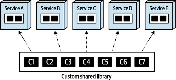
Figure 8-3. With the shared library technique, common code is consolidated and shared at compile time
Dependency Management and Change Control
Similar to service granularity (discussed in Chapter 7), there are trade-offs associated with the granularity of a shared library.
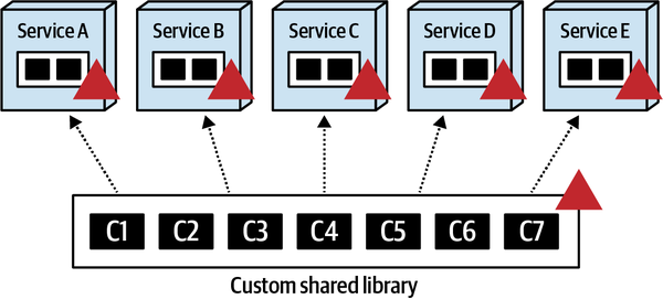
Figure 8-4. Changes to coarse-grained shared libraries impact multiple services but keep dependencies low
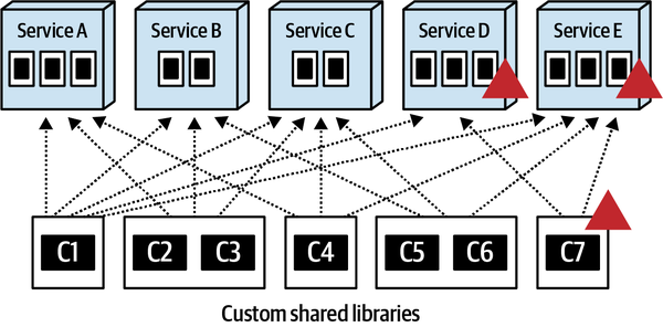
Figure 8-5. Changes to fine-grained shared libraries impact fewer services but increase dependencies
The choice of shared library granularity may not matter much with only a few services, but as the number of services increases, so do the issues associated with change control and dependency management. Just imagine a system with 200 services and 40 shared libraries—it would quickly become overly complex and unmaintainable.
Given these trade-offs of change control and dependency management, our advice is to generally avoid large, coarse-grained shared libraries and strive for smaller, functionally partitioned libraries whenever possible, thus favoring change control over dependency management. For example, carving off relatively static functionality such as formatters and security (authentication and authorization) into their own shared libraries isolates this static code, therefore reducing the testing scope and unnecessary version deprecation deployments for other shared functionality.
Versioning Strategies
Our general advice about shared library versioning
To illustrate this point, consider a shared library containing common field validation rules called Validation.jar that is used by 10 services. Suppose one of those services needs an immediate change to one of the validation rules. By versioning the Validation.jar file, the service needing the change can immediately incorporate the new Validation.jar version and be deployed to production right away, without any impact to the other 9 services. Without versioning, all 10 services would have to be tested and redeployed when making the shared library change, thereby increasing the amount of time and coordination for the shared library change (hence less agility).
One of the first complexities of shared library versioning is communicating a version change. In a highly distributed architecture with multiple teams, it is often difficult to communicate a version change to a shared library. How do other teams know that Validation.jar just increased to version 1.5? What were the changes? What services are impacted? What teams are impacted? Even with the plethora of tools that manage shared libraries, versions, and change documentation (such as JFrog Artifactory), version changes must nevertheless be coordinated and communicated to the right people at the right time.
Another complexity is the deprecation of older versions of a
Assigning a custom deprecation strategy to each shared library is usually the desired approach because libraries change at different rates. For example, if a Security.jar shared library doesn’t change often, maintaining only two or three versions is a reasonable strategy. However, if the Calculators.jar shared library changes weekly, maintaining only two or three versions means that all services using that shared library will be incorporating a newer version on a monthly (or even weekly) basis—causing a lot of unnecessary frequent retesting and redeployment. Therefore, maintaining 10 versions of Calculators.jar would be a much more reasonable strategy because of the frequency of change. The trade-off of this approach, however, is that someone must maintain and track the deprecation for each shared library. This can sometimes be a daunting task and is definitely not for the faint of heart.
Because change is variable among the various shared libraries, the global deprecation strategy, while simpler, is a less effective approach. The global deprecation strategy dictates that all shared libraries, regardless of the rate of change, will not support more than a certain number of backward versions (for example, four). While this is easy to maintain and govern, it can cause significant churn--the constant retesting and redeploying of services—just to maintain compatibility with the latest version of a frequently changed shared library. This can drive teams crazy and significantly reduce overall team velocity and productivity.
Regardless of the deprecation strategy used, serious defects or breaking changes to shared code invalidate any sort of deprecation strategy, causing all services to adopt the latest version of a shared library at once (or within a very short period of time). This is another reason we recommend keeping shared libraries as fine-grained as appropriate and avoid the coarse-grained SharedStuff.jar type of libraries containing all the shared functionality in the system.
LATEST version when specifying which version of a library a service requires. It has been our experience that services using the LATEST version experience issues when doing quick fixes or emergency hot deployments into production, because something in the LATEST version might be incompatible with the service, therefore causing additional development and testing effort for the team to release the service into production.When To Use
The shared library technique is a good approach for homogeneous environments where shared code change is low to moderate. The ability to version (although sometimes complex) allows for good levels of agility when making shared code changes. Because shared libraries are usually bound to the service at compile time, operational characteristics such as performance, scalability, and fault tolerance are not impacted, and the risk of breaking other services with a change to common code is low because of versioning.
Shared Service
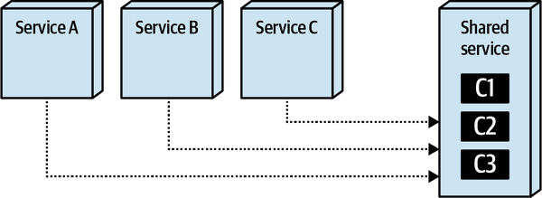
Figure 8-6. With the shared service technique, common functionality is made available at runtime through separate services
One distinguishing factor about the shared service technique is
Back in the day, shared services were a common approach to address shared functionality within a distributed architecture. Changes to shared functionality no longer require redeployment of services; rather, since changes are isolated to a separate service, they can be deployed without redeploying other services needing the shared functionality. However, like everything in software architecture, many trade-offs are associated with using shared services, including change risk, performance, scalability, and fault tolerance.
Change Risk
Changing shared functionality using the shared service technique turns out to be a double-edged sword.
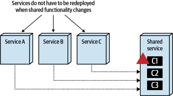
Figure 8-7. Shared functionality changes are isolated to only the shared service
If only life were that simple! The problem, of course, is that a
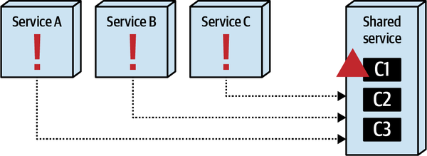
Figure 8-8. Changes to a shared service can break other services at runtime
This necessarily brings to the forefront the topic of versioning. In the shared library technique, versioning is managed through compile-time bindings, significantly reducing risk associated with a change in a shared library. However, how does one version a simple shared service change?
Example 8-3. Discount calendar with versioning for shared service endpoint
app/1.0/discountcalc?orderid=123app/1.1/discountcalc?orderid=123app/1.2/discountcalc?orderid=123app/1.3/discountcalc?orderid=123latest change -> app/1.4/discountcalc?orderid=123
Using this approach, each time a shared service changes, the team would create a new API endpoint containing a new version of the URI. It’s not difficult to see the issues that arise with this practice. First of all, services accessing the discount calculator service (or the corresponding configuration for each service) must change to point to the correct version. Second, when should the team create a new API endpoint? What about for a simple error message change? What about for a new calculation? Versioning starts to become largely subjective at this point, and the services using the shared service must still change to point to the correct endpoint.
Another problem with API endpoint versioning is that it assumes all
The bottom line is that with the shared service technique, changes to a shared service are generally runtime in nature, and therefore carry much more risk than with shared libraries. While versioning can help reduce this risk, it’s much more complex to apply and manage than that of a shared library.
Performance
Because services requiring the shared functionality must make an
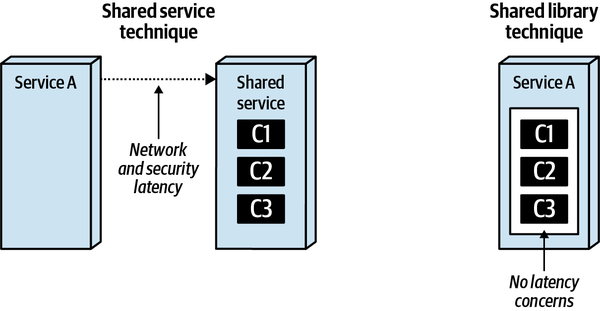
Figure 8-9. Shared service introduces network and security latency
Use of gRPC can help mitigate some of the
Scalability
Another drawback of the shared service technique is that the shared
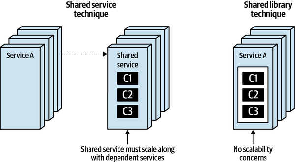
Figure 8-10. Shared services must scale as dependent services scale
Fault Tolerance
While fault-tolerance issues can usually be mitigated through
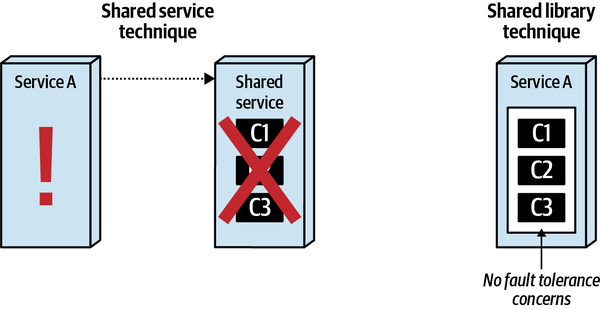
Figure 8-11. Shared services introduce fault-tolerance issues
When to Use
The shared service technique is good to use in highly polyglot environments (those with multiple heterogeneous languages and platforms), and also when shared functionality tends to change often. While changes in a shared service tend to be much more agile overall than with the shared library technique, be careful of runtime side-effects and risks to services needing the shared functionality.
Sidecars and Service Mesh
One of the design goals of microservices architectures is a high degree of decoupling, often manifested in the advice “Duplication is preferable to coupling.” For example, let’s say that two Sysops Squad services need to pass customer information, yet the domain-driven design bounded context insists that implementation details remain private to the service. Thus, a common solution allows each service its own internal representation of entities such as Customer, passing that information in loosely coupled ways such as name-value pairs in JSON. Notice that this allows each service to change its internal representation at will, including the technology stack, without breaking the integration. Architects generally frown on duplicating code because it causes synchronization issues, semantic drift, and a host of other issues, but sometimes forces exist that are worse than the problems of duplication, and coupling in microservices often fits that bill. Thus, in microservices architecture, the answer to the question of “should we duplicate or couple to some capability?” is likely duplicate, whereas in another architecture style such as a service-based architecture, the correct answer is likely couple. It depends!
When designing microservices, architects have resigned themselves to the reality of implementation duplication to preserve decoupling. But what about the type of capabilities that benefit from high coupling? For example, consider common operational capabilities such as monitoring, logging, authentication and authorization, circuit breakers, and a host of other operational abilities that each service should have. But allowing each team to manage these dependencies often descends into chaos. For example, consider a company like Penultimate Electronics trying to standardize on a common monitoring solution to make it easier to operationalize the various services. Yet if each team is responsible for implementing monitoring for their service, how can the operations team be sure they did? Also, what about issues such as unified upgrades? If the monitoring tool needs to upgrade across the organization, how can teams coordinate that?
In this Hexagonal pattern, what we would now call the domain logic resides in the center of the hexagon, which is surrounded by ports and adaptors to other parts of the ecosystem (in fact, this
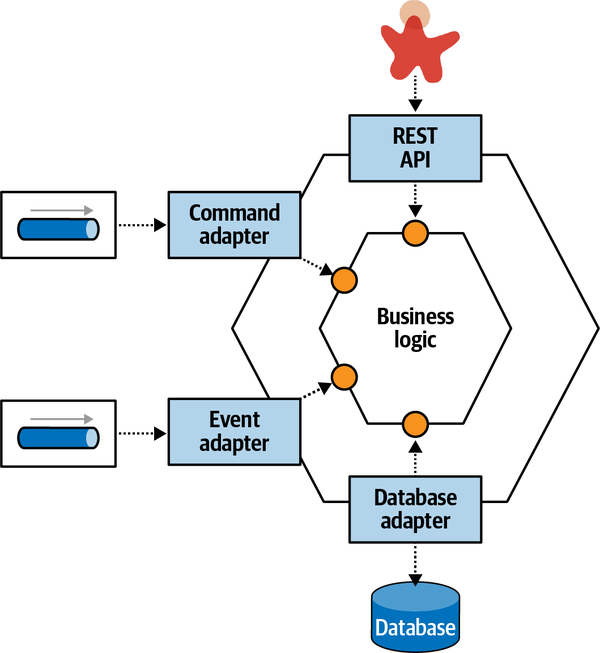
Figure 8-12. The Hexagonal pattern separated domain logic from technical coupling
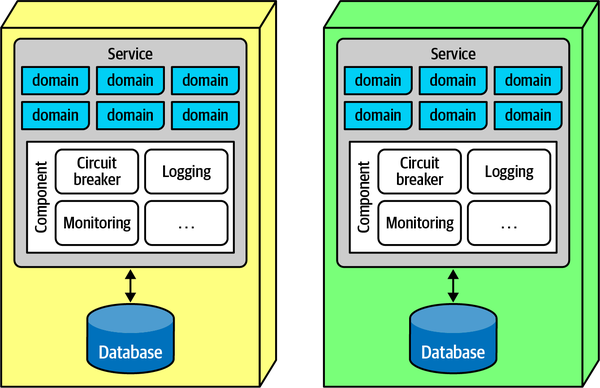
Figure 8-13. Two microservices that share the same operational capabilities
Here, each service includes a split between operational concerns (the larger components toward the bottom of the service) and domain concerns, pictured in the boxes toward the top of the service labeled “domain.” If architects desire consistency in operational capabilities, the separable parts go into a sidecar component, metaphorically named for the sidecar that attaches to motorcycles, whose implementation is either a shared responsibility across teams or managed by a centralized infrastructure group. If architects can assume that every service includes the sidecar, it forms a consistent operational interface across services, typically attached via a service plane, shown in Figure 8-14.
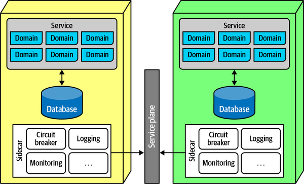
Figure 8-14. When each microservice includes a common component, architects can establish links between them for consistent control
If architects and operations can safely assume that every service includes
Having a mesh allows architects and DevOps to create dashboards, control operational characteristics such as scale, and a host of other capabilities.
The Sidecar pattern allows governance groups like enterprise architects a reasonable restraint over too many polyglot environments: one of the advantages of microservices is a reliance on integration rather than a common platform, allowing teams to choose the correct level of complexity and capabilities on a service-by-service basis. However, as the number of platforms proliferates, unified governance becomes more difficult. Therefore, teams often use the consistency of the service mesh as a driver to support infrastructure and other cross-cutting concerns across multiple heterogeneous platforms. For example, without a service mesh, if enterprise architects want to unify around a common monitoring solution, then teams must build a sidecar per platform that supports that solution.
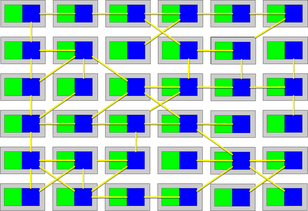
Figure 8-15. A service mesh is an operational link among services
The Sidecar pattern represents not only a way to decouple operational capabilities from domains—it’s
While the Sidecar pattern offers a nice abstraction, it has trade-offs like all other architectural approaches, shown in Table 8-4.
When to Use
The Sidecar pattern and service mesh offer a clean way to spread some sort of cross-cutting concern across a distributed architecture, and can be used by more than just operational coupling (see Chapter 14).
Sysops Squad Saga: Common Infrastructure Logic
Thursday, February 10, 10:34
Taylen replied, “Yes, we’re trying to consolidate on that to get some consistency on message resolution.”
Sydney said, “OK, but now we’re getting double log messages—it looks like the library writes to the logs, but our service also writes to the log. Is that as it should be?”
“No,” Taylen replied. “We definitely don’t want duplicate log entries. That just makes everything confusing. We should ask Addison about that.”
Consequently, Sydney and Taylen darkened Addison’s door. “Hey, do you have a minute?”
Addison replied, “Always for you—what’s up?”
Sydney said, “We’ve been consolidating a bunch of our duplicated code into shared libraries, and that’s working well—we’re getting better at identifying the parts that rarely change. But, now we’ve hit the problem that brings us here—who is supposed to be writing log messages? Libraries, services, or something else? And, how can we make that consistent?”
Addison said, “We’ve bumped into operational shared behavior. Logging is just one of them. What about monitoring, service discovery, circuit breakers, even some of our utility functions, like the JSONtoXML library that a few teams are sharing? We need a better way to handle this to prevent issues. That’s why we’re in the process of implementing a service mesh with this common behavior in a sidecar component.”
Sydney said, “I’ve read about sidecars and service mesh—it’s a way to share things across a bunch of microservices, right?”
Addison said, “Sort of, but not all kinds of things. The intent of the service mesh and sidecar is to consolidate operational coupling, not domain coupling. For example, just like in our case, we want consistency for logging and monitoring across all our services, but don’t want each team to have to worry about that. If we consolidate logging code into the common sidecar that every service implements, we can enforce consistency.”
Taylen asked, “Who owns the shared library? Shared responsibility across all the teams?”
Addison replied, “We thought about that, but we have enough teams now; we’ve built a shared infrastructure team that is going to manage and maintain the sidecar component. They have built the deployment pipeline to automatically test the sidecar once it’s been bound into the service with a set of fitness functions.”
Sydney said, “So if we need to share libraries between services, just ask them to put it in the sidecar?”
Addison said, “Be careful—the sidecar isn’t meant to be used for just anything, only operational coupling.”
“I’m not sure what that distinction is,” Taylen said.
“Operational coupling includes the things we’ve been discussing—logging, monitoring, service discovery, authentication and authorization, and so on. Basically, it covers all the plumbing parts of the infrastructure that have no domain responsibility. But you should never put domain shared components, like the Address or Customer class, in the sidecar.”
Sydney asked, “But why? What if I need the same class definition in two services? Won’t putting it in the sidecar make it available to both?”
Addison replied, “Yes, but now you are increasing coupling in exactly the way we try to avoid in microservices. In most architectures, a single implementation of that service would be shared across the teams that need it. However, in microservices, that creates a coupling point, tying several services together in an undesirable way—if one team changes the shared code, every team must coordinate with that change. However, the architects could decide to put the shared library in the sidecar—it is, after all a technical capability. Neither answer is unambiguously correct, making this an architect decision and worthy of trade-off analysis. For example, if the Address class changes and both services rely on it, they must both change—the definition of coupling. We handle those issues with contracts. The other issue concerns size: we don’t want the sidecar to become the biggest part of the architecture. For example, consider the JSONtoXML library we were discussing before. How many teams use that?”
Taylen said, “Well, any team that has to integrate with the mainframe system for anything—probably 5 out of, what, 16 or 17 teams?”
Addison said, “Perfect. OK, what’s the trade-off of putting the JSONtoXML in the sidecar?”
Sydney answered, “Well, that means that every team automatically has the library and doesn’t have to wire it in through dependencies.”
“And the bad side?” asked Addison.
“Well, adding it to the sidecar makes it bigger, but not by much—it’s a small library.” said Sydney.
“That’s the key trade-off for shared utility code—how many teams need it versus how much overhead does it add to every service, particularly ones that don’t need it.”
“And if less than one-half the teams use it, it’s probably not worth the overhead,” Sydney said.
“Right! So, for now, we’ll leave that out of the sidecar and perhaps reassess in the future,” said Addison.
ADR: Using a Sidecar for Operational Coupling
Context
Each service in our microservices architecture requires common and consistent operational behavior; leaving that responsibility to each team introduces inconsistencies and coordination issues.Decision
We will use a sidecar component in conjunction with a service mesh to consolidate shared operational coupling.The shared infrastructure team will own and maintain the sidecar for service teams; service teams act as their customers. The following services will be provided by the sidecar:
Monitoring
Logging
Service discovery
Authentication
Authorization
Consequences
Teams should not add domain classes to the sidecar, which encourages inappropriate coupling.Teams work with the shared infrastructure team to place shared, operational libraries in the sidecar if enough teams require it.
Code Reuse: When Does It Add Value?
Reuse is one of the most abused abstractions, because the general view in organizations is that reuse represents a laudable goal that teams should strive for. However, failing to evaluate all the trade-offs associated with reuse can lead to serious problems within architecture.
The danger of too much reuse was one of the lessons many architects learned from the early 20th century trend of orchestration-driven service-oriented architecture, where one of the primary goals for many organizations was to maximize reuse.
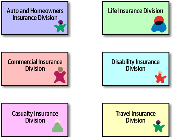
Figure 8-16. Each domain within a large insurance company has a view of the customer
Each division in the company has some aspect of customers it cares about. Years ago, architects were instructed to keep an eye out for this type of commonality; once discovered, the goal was to consolidate the organizational view of customer into a single service, shown in Figure 8-17.
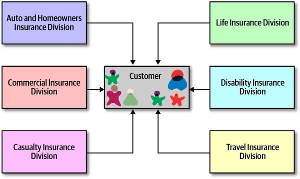
Figure 8-17. Unifying on a centralized Customer service
While the picture in Figure 8-17 may seem logical, it’s an architectural disaster for two reasons. First, if all institutional information about a key entity like Customer must reside in a single place, that entity must be complex enough to handle any domain and scenario, making it difficult to use for simple things.
Secondly, though, it creates brittleness within the architecture.
CustomerService needs to add new capabilities on behalf of one of the domains? That change could potentially impact every other domain, requiring coordination and testing to ensure that the change hasn’t “rippled” throughout the architecture.What architects failed to realize is that reuse has two important aspects; they got the first one correct: abstraction. The way architects and developers discover candidates for reuse is via abstraction. However, the second consideration is the one that determines utility and value: rate of change.
Observing that some reuse causes brittleness begs the question about how that kind of reuse differs from the kinds we clearly benefit from. Consider things that everyone successfully reuses: operating systems, open source frameworks and libraries, and so on. What distinguishes those from assets that project teams build? The answer is slow rate of change. We benefit from technical coupling, like operating systems and external frameworks, because they have a well-understood rate of change and update cadence. Internal domain capabilities or quick-changing technical frameworks make terrible coupling targets.
Tip
Reuse is derived via abstraction but operationalized by slow rate of change.
Reuse via Platforms
Slow rate of change drives this reasoning. As we discuss in Chapter 13, an API can be designed to be quite loosely coupled to callers, allowing for an aggressive internal rate of change of implementation details without breaking the API. This, of course, doesn’t protect the organization from changes to the semantics of the information it must pass between domains, but by careful design of encapsulation and contracts, architects can limit the amount of breaking change and brittleness in integration architecture.
Sysops Squad Saga: Shared Domain Functionality
Tuesday, February 8, 12:50
With Addison’s approval, the development team had decided to split
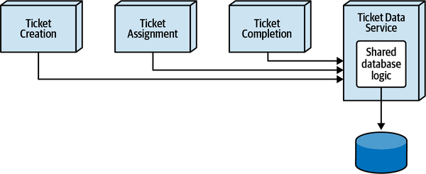
Figure 8-18. Option using a shared Ticket Data service for common database logic for the Sysops Squad ticketing services
Skyler hated the idea and wanted to use a single shared library (DLL) that each service would include as part of the build and deployment, as illustrated in Figure 8-19.
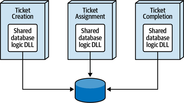
Figure 8-19. Option using a shared library for common database logic for the Sysops Squad ticketing services
Both developers met with Addison to resolve this roadblock.
“So, Addison, what is your opinion? Should the shared database logic be in a shared data service or a shared library?” asked Taylen.
“It’s not about opinions,” said Addison. “It’s about analyzing the trade-offs to arrive at the most appropriate solution for the core shared ticketing database functionality. Let’s do a hypothesis-based approach and hypothesize that the most appropriate solution is to use the shared data service.”
“Hold on,” said Skyler. “It’s simply not a good architectural solution for this problem.”
“Why?” asked Addison, prompting Skyler to start thinking in terms of trade-offs.
“First of all,” said Skyler, “all three services would need to make an interservice call to the shared data service for every database query or update. We’re going take a serious performance hit if we do that. Furthermore, if the shared data service goes down, all three of those services become nonoperational.”
“So?” said Taylen. “It’s all backend functionality, so who cares? The backend functionality doesn’t have to be that fast, and services come up fairly quickly if they fail.”
“Actually,” said Addison, “it’s not all backend functionality. Don’t forget, the Ticket Creation service is customer facing, and it would be using the same shared data service as the backend ticketing functionality.”
“Yeah, but most of the functionality is still backend,” said Taylen, with a little less confidence than before.
“So far,” said Addison, “it looks like the trade-off for using the shared data service is performance and fault tolerance for the ticketing services.”
“Let’s also not forget that any changes made to the shared data service are runtime changes. In other words,” said Skyler, “if we make a change and deploy the shared data service, we could possibly break something.”
“That’s why we test,” said Taylen.
“Yeah, but if you want to reduce risk you would have to test all of the ticketing services for every change to the shared data service, which increases testing time significantly. With a shared DLL, we could version the shared library to provide backward compatibility,” said Skyler.
“OK, we will add increased risk for changes and increased testing effort to the trade-offs as well,” said Addison. “Also, let’s not forget that we would have extra coordination from a scalability standpoint. Every time we create more instances of the ticket creation service, we would have to make sure we create more instances of the shared data service as well.”
“Let’s not keep focusing so much on the negatives.” said Taylen. “How about the positives of using a shared data service?”
“OK,” said Addison, “let’s talk about the benefits of using a shared data service.”
“Data abstraction, of course,” said Taylen. “The services wouldn’t have to worry about any database logic. All they would have to do is make a remote service call to the shared data service.”
“Any other benefits?” asked Addison.
“Well,” said Taylen, “I was going to say centralized connection pooling, but we would need multiple instances anyway to support the customer ticket creation service. It would help, but it’s not a major game changer since there are only three services without a lot of instances of each service. However, change control would be so much easier with a shared data service. We wouldn’t have to redeploy any of the ticketing services for database logic changes.”
“Let’s take a look at those shared class files in the repository and see historically how much change there really is for that code,” said Addison.
Addison, Taylen, and Skyler all looked at the repository history for the shared data logic class files.
“Hmm…” said Taylen, “I thought there were a lot more changes to that code than what is showing up in the repo. OK, so I guess the changes are fairly minimal for the shared database logic after all.”
Through the conversation of discussing trade-offs, Taylen started to realize that the negatives of a shared service seemed to outweigh the positives, and there was no real compelling justification for putting the shared database logic in a shared service. Taylen agreed to put the shared database logic in a shared DLL, and Addison wrote an ADR for this architecture decision:
ADR: Use of a Shared Library for Common Ticketing Database Logic
Context
The ticketing functionality is broken into three services: Ticket Creation, Ticket Assignment, and Ticket Completion. All three services use common code for the bulk of the database queries and update statements. The two options are to use a shared library or create a shared data service.Decision
We will use a shared library for the common ticketing database logic.Using a shared library will improve performance, scalability, and fault tolerance of the customer-facing Ticket Creation service, as well as for the Ticket Assignment service.
We found that the common database logic code does not change much and is therefore fairly stable code. Furthermore, change is less risky for the common database logic because services would need to be tested and redeployed. If changes are needed, we will apply versioning where appropriate so that not all services need to be redeployed when the common database logic changes.
Using a shared library reduces service coupling and eliminates additional service dependencies, HTTP traffic, and overall bandwidth.
Consequences
Changes to the common database logic in the shared DLL will require the ticketing services to be tested and deployed, therefore reducing overall agility for common database logic for the ticketing functionality.Service instances will need to manage their own database connection pool.
Chapter 9. Data Ownership and Distributed Transactions
Friday, December 10 09:12
While the database team worked on decomposing the monolithic
“Why did you add the expert profile table to the bounded context of the Ticket Assignment service?” asked Addison.
“Because,” said Sydney, “the ticket assignment relies on that table for the assignment algorithms. It constantly queries that table to get the expert’s location and skills information.”
“But it only does queries to the expert table,” said Addison. “The User Maintenance service contains the functionality to perform database updates to maintain that information. Therefore, it seems to me the expert profile table should be owned by the User Maintenance service and put within that bounded context.”
“I disagree,” said Sydney. “We simply cannot afford for the assignment service to make remote calls to the User Maintenance service for every query it needs. It simply won’t work.”
“In that case, how to you see updates occurring to the table when an expert acquires a new skill or changes their service location? And what about when we hire a new expert?” asked Addison. “How would that work?”
“Simple,” said Sydney. “The User Maintenance service can still access the expert table. All it would need to do is connect to a different database. What’s the big deal about that?”
“Don’t you remember what Dana said earlier? It’s OK for multiple services to connect to the same database schema, but it’s not OK for a service to connect to multiple databases or schemas. Dana said that was a no-go and would not allow that to happen,” said Addison.
“Oh, right, I forgot about that rule. So what do we do?” asked Sydney. “We have one service that needs to do occasional updates, and an entirely different service in an entirely different domain to do frequent reads from the table.”
“I don’t know what the right answer is,” said Addison. “Clearly this is going to require more collaboration between the database team and us to figure these things out. Let me see if Dana can provide any advice on this.”
Once data is pulled apart, it must be stitched back together to make the system work. This means figuring out which services own what data, how to manage distributed transactions, and how services can access data they need (but no longer own). In this chapter, we explore the ownership and transactional aspects of putting distributed data back together.
Assigning Data Ownership
The general rule of thumb for assigning table ownership states that services that perform write operations to a table own that table. While this general rule of thumb works well for single ownership (only one service ever writes to a table), it gets messy when teams have joint ownership (multiple services do writes to the same table) or even worse, common ownership (most or all services write to the table).
Tip
The general rule of thumb for data ownership is that the service that performs write operations to a table is the owner of that table. However, joint ownership makes this simple rule complex!
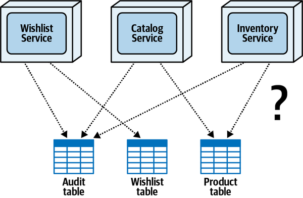
Figure 9-1. Once data is broken apart, tables must be assigned to services that own them
To further complicate matters, notice that the Wishlist Service writes to both the Audit table and the Wishlist table, the Catalog Service writes to the Audit table and the Product table, and the Inventory Service writes to the Audit table and the Product table. Suddenly, this simple real-world example makes assigning data ownership a complex and confusing task.
In this chapter, we unravel this complexity by discussing the three scenarios encountered when assigning data ownership to services (single ownership, common ownership, and joint ownership), and exploring techniques for resolving these scenarios, using Figure 9-1 as a common reference point.
Single Ownership Scenario
Single table ownership occurs when only one service writes to a
In this scenario, it is clear that the Wishlist Service should be the owner of the Wishlist table (regardless of other services that need read-only access to the Wishlist table), see Figure 9-2. Notice that on the right side of this diagram, the Wishlist table becomes part of the bounded context of the Wishlist Service. This diagramming technique is an effective way to indicate table ownership and the bounded context formed between the service and its corresponding data.
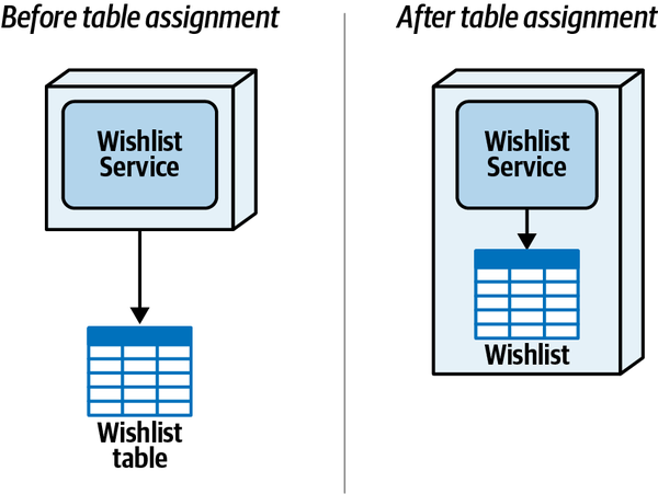
Figure 9-2. With single ownership, the service that writes to the table becomes the table owner
Because of the simplicity of this scenario, we recommend addressing single table ownership relationships first to clear the playing field in order to better address the more complicated scenarios that arise: common ownership and joint ownership.
Common Ownership Scenario
Common table ownership occurs when most (or all) of the services need to write to the same table.
The solution of simply putting the Audit table in a shared database or shared schema that is used by all services unfortunately reintroduces all of the data-sharing issues described at the beginning of Chapter 6, including change control, connection starvation, scalability, and fault tolerance. Therefore, another solution is needed to solve common data ownership.
A popular technique for addressing common table ownership is to assign a dedicated single service as the primary (and only) owner of that data, meaning only one service is responsible for writing data to the table.
If no information or acknowledgment is needed by services sending the data, services can use persisted queues for asynchronous fire-and-forget messaging. Alternatively, if information needs to be returned to the caller based on a write action (such as returning a confirmation number or database key), services can use something like REST, gRPC, or request-reply messaging (pseudosynchronous) for a synchronous call.
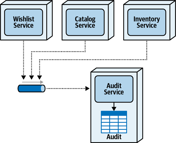
Figure 9-3. Common ownership uses a dedicated service owner
In some cases, it may be necessary for services to read common data they don’t own. These read-only access techniques are described in detail in Chapter 10.
Joint Ownership Scenario
One of the more common (and complex) scenarios involving data
Figure 9-4 shows the isolated joint ownership example from Figure 9-1. The Catalog Service inserts new products into the table, removes products no longer offered, and updates static product information as it changes, whereas the Inventory Service is responsible for reading and updating the current inventory for each product as products are queried, sold, or returned.
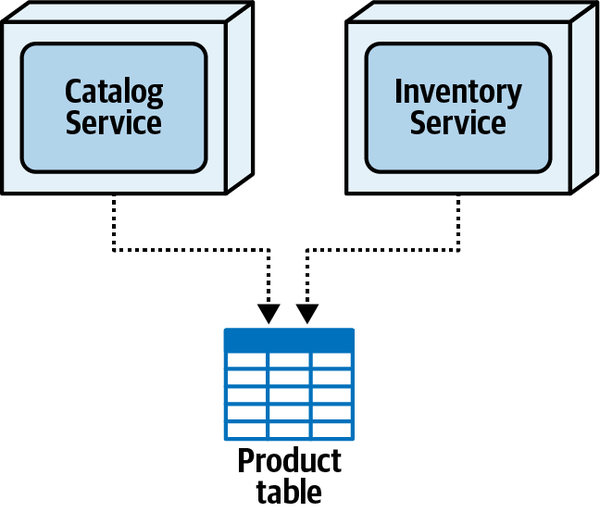
Figure 9-4. Joint ownership occurs when multiple services within the same domain perform write operations on the same table
Fortunately, several techniques exist to address this type of ownership scenario—the table split technique, the data domain technique, the delegation technique, and the service consolidation technique. Each is discussed in detail in the following sections.
Table Split Technique
The table split technique breaks a single table into multiple tables
To illustrate the table split technique, consider the Product table example illustrated in Figure 9-4. In this case, the architect or developer would first create a separate Inventory table containing the product ID (key) and the inventory count (number of items available), pre-populate the Inventory table with data from the existing Product table, then finally remove the inventory count column from the Product table. The source listing in Example 9-1 shows how this technique might be implemented using data definition language (DDL) in a typical relational database.
Example 9-1. DDL source code for splitting up the Product table and moving inventory counts to a new Inventory table
CREATETABLEInventory(product_idVARCHAR(10),inv_cntINT);INSERTINTOInventoryVALUES(product_id,inv_cnt)ASSELECTproduct_id,inv_cntFROMProduct;COMMIT;ALTERTABLEProductDROPCOLUMNinv_cnt;
Splitting the database table moves the joint ownership to a single table ownership scenario: the Catalog Service owns the data in the Product table, and the Inventory Service owns the data in the Inventory table. However, as shown in Figure 9-5, this technique requires communication between the Catalog Service and Inventory Service when products are created or removed to ensure the data remains consistent between the two tables.
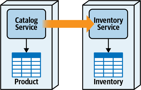
Figure 9-5. Joint ownership can be addressed by breaking apart the shared table
For example, if a new product is added, the Catalog Service generates a product ID and inserts the new product into the Product table. The Catalog Service then must send that new product ID (and potentially the initial inventory counts) to the Inventory Service. If a product is removed, the Catalog Service first removes the product from the Product table, then must notify the Inventory Service to remove the inventory row from the Inventory table.
Synchronizing data between split tables is not a trivial matter. Should communication between the Catalog Service and the Inventory Service be synchronous or asynchronous? What should the Catalog Service do when adding or removing a product and finding that the Inventory Service is not available? These are hard questions to answer, and are usually driven by the traditional availability verses consistency trade-off commonly found in distributed architectures. Choosing availability means that it’s more important that the Catalog Service always be able to add or remove products, even though a corresponding inventory record may not be created in the Inventory table. Choosing consistency means that it’s more important that the two tables always remain in sync with each other, which would cause a product creation or removal operation to fail if the Inventory Service is not available. Because network partitioning is necessary in distributed architectures, the CAP theorem states that only one of these choices (consistency or availability) is possible.
The type of communication protocol (synchronous versus asynchronous) also matters when splitting a table. Does the Catalog Service require a confirmation that the corresponding Inventory record is added when creating a new product? If so, then synchronous communication is required, providing better data consistency at the sacrifice of performance. If no confirmation is required, the Catalog Service can use asynchronous fire-and-forget communication, providing better performance at the sacrifice of data consistency. So many trade-offs to consider!
Table 9-1 summarizes the trade-offs associated with the table split technique for joint ownership.
Data Domain Technique
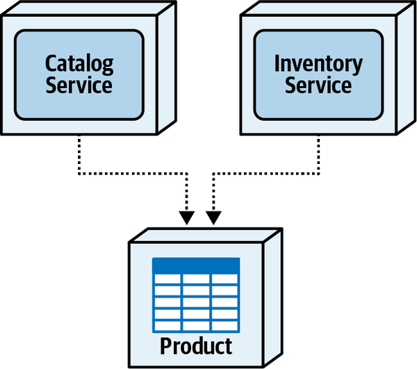
Figure 9-6. With joint ownership, services can share data by using the data domain technique (shared schema)
While data sharing is generally discouraged in distributed architectures
Tip
Unfortunately, sharing data in a distributed architecture introduces a number of issues, the first of these being increased effort for changes made to the structure of the data (such as changing the schema of a table). Because a broader bounded context is formed between the services and the data, changes to the shared table structures may require those changes to be coordinated among multiple services. This increases development effort, testing scope, and deployment risk.
Another issue with the data domain technique with regard to data ownership is controlling which services have write responsibility to what data. In some cases, this might not matter, but if it’s important to control write operations to certain data, additional effort is required to apply specific governance rules to maintain specific table or column write ownership.
Table 9-2 summarizes the trade-offs associated with the data domain technique for the joint ownership scenario.
Delegate Technique
One of the challenges of the delegate technique is knowing which service to assign as the delegate (the sole owner of the table). The first option, called primary domain priority, assigns table ownership to the service that most closely represents the primary domain of the data—in other words, the service that does most of the primary entity CRUD operations for the particular entity within that domain. The second option, called operational characteristics priority, assigns table ownership to the service needing higher operational architecture characteristics, such as performance, scalability, availability, and throughput.
With the primary domain priority option, the service that performs most of the CRUD operations on the main entity becomes the owner of the table. As illustrated in Figure 9-7, since the Catalog Service performs most of the CRUD operations on product information, the Catalog Service would be assigned as the single owner of the table. This means that the Inventory service must communicate with the Catalog Service to retrieve or update inventory counts since it doesn’t own the table.
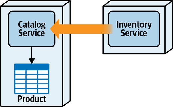
Figure 9-7. Table ownership is assigned to the Catalog service because of domain priority
Like the common ownership scenario described earlier, the delegate technique
With synchronous communication, the Inventory Service must wait for the inventory to be updated by the Catalog Service, which impacts overall performance but ensures data consistency. Using asynchronous communication to send inventory updates makes the Inventory Service perform much faster, but the data is only eventually consistent. Furthermore, with asynchronous communication, because an error can occur in the Catalog Service while trying to update inventory, the Inventory Service has no guarantee that the inventory was ever updated, impacting data integrity as well.
With this option, frequent updates to inventory counts can use direct database calls rather than remote access protocols, therefore making inventory operations much faster and more reliable. In addition, the most volatile data (inventory count) is kept highly consistent.
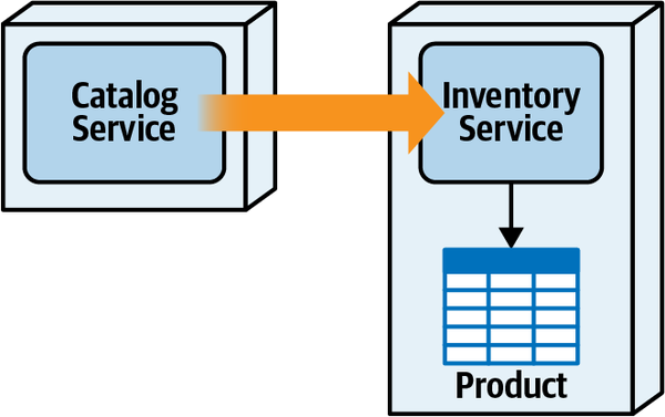
Figure 9-8. Table ownership is assigned to the Inventory Service because of operational characteristics priority
However, one major problem with the diagram illustrated in Figure 9-8 is that of domain management responsibility. The Inventory Service is responsible for managing product inventory, not the database activity (and corresponding error handling) for adding, removing, and updating static product information. For this reason, we usually recommend the domain priority option, and leveraging things like a replicated in-memory cache or a distributed cache to help address performance and fault-tolerance issues.
Regardless of which service is assigned as the delegate (sole table owner), the delegate technique has some disadvantages, the biggest being service coupling and the need for interservice communication. This in turn leads to other issues for nondelegate services, including the lack of an atomic transaction when performing write operations, low performance due to network and processing latency, and low fault tolerance. Because of these issues, the delegate technique is generally better suited for database write scenarios that do not require atomic transactions and that can tolerate eventual consistency through asynchronous communications.
Service Consolidation Technique
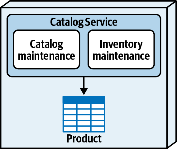
Figure 9-9. Table ownership is resolved by combining services
Like the data domain technique, this technique resolves issues associated with service dependencies and performance, while at the same time addressing the joint ownership problem. However, like the other techniques, it has its share of trade-offs as well.
Combining services creates a more coarse-grained service, thereby increasing the overall testing scope as well as overall deployment risk (the chance of breaking something else in the service when a new feature is added or a bug is fixed). Consolidating services might also impact overall fault tolerance since all parts of the service fail together.
Overall scalability is also impacted when using the service consolidation
Catalog service) must unnecessarily scale to meet the high demands of the inventory retrieval and update functionality. Table 9-4 summarizes the overall trade-offs of the service consolidation technique.
Data Ownership Summary
Figure 9-10 shows the resulting
Once table ownership has been assigned to services, an architect must then validate the table ownership assignments by analyzing business workflows and their corresponding transaction requirements.
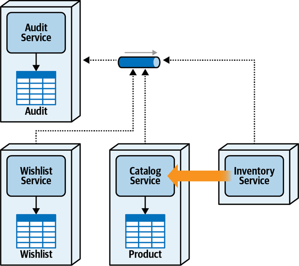
Figure 9-10. Resulting data ownership using delegate technique for joint ownership
Distributed Transactions
When architects and developers think about transactions, they usually
Atomicity means a transaction must either commit or roll back all of its updates in a single unit of work, regardless of the number of updates made during that transaction. In other words, all updates are treated as a collective whole, so all changes either get committed or get rolled back as one unit. For example, assume registering a customer involves inserting customer profile information into a Customer Profile table, inserting credit card information into a Wallet table, and inserting security-related information into a Security table. Suppose the profile and credit card information are successfully inserted, but the security information insert fails. With atomicity, the profile and credit card inserts would be rolled back, keeping the database tables in sync.
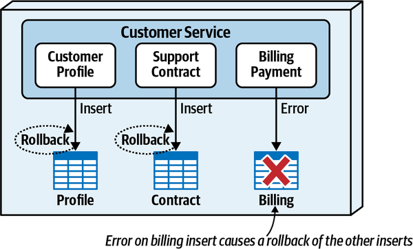
Figure 9-11. With ACID transactions, an error on the billing insert causes a rollback to the other table inserts
First, notice that with an ACID transaction, because an error occurred when trying to insert the billing information, both the profile information and support contract information that were previously inserted are now rolled back (that’s the atomicity and consistency parts of ACID). While not illustrated in the diagram, data inserted into each table during the course of the transaction is not visible to other requests (that’s the isolation part of ACID).
Note that ACID transactions can exist within the context of each service in a distributed architecture, but only if the corresponding database supports ACID properties as well. Each service can perform its own commits and rollbacks to the tables it owns within the scope of the atomic business transaction.
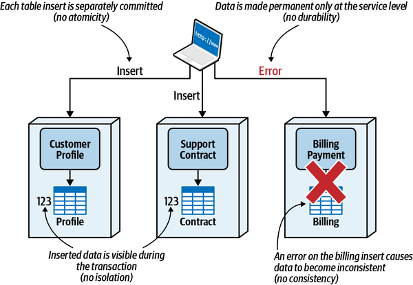
Figure 9-12. Distributed transactions do not support ACID properties
As you can see, distributed transactions do not support ACID properties.
Atomicity is not supported because each separately deployed
Isolation is not supported because once the Customer Profile Service inserts
Eventual consistency (the E part of BASE) means that given enough time,
Eventual Consistency Patterns
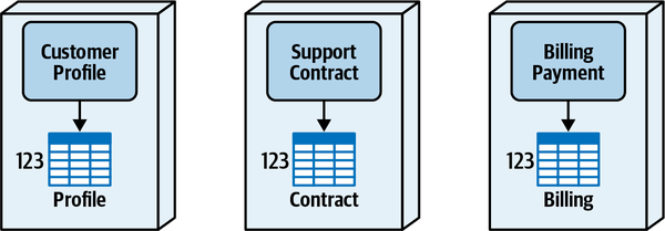
Figure 9-13. Customer 123 is a subscriber in the Sysops Squad application
Customer 123 decides they are no longer interested in the Sysops Squad support plan, so they unsubscribe from the service. As shown in Figure 9-14, the Customer Profile Service receives this request from the user interface, removes the customer from the Profile table, and returns a confirmation to the customer that they are successfully unsubscribed and will no longer be billed. However, data for that customer still exists in the Contract table owned by the Support Contract Service and the Billing table owned by the Billing Payment Service.
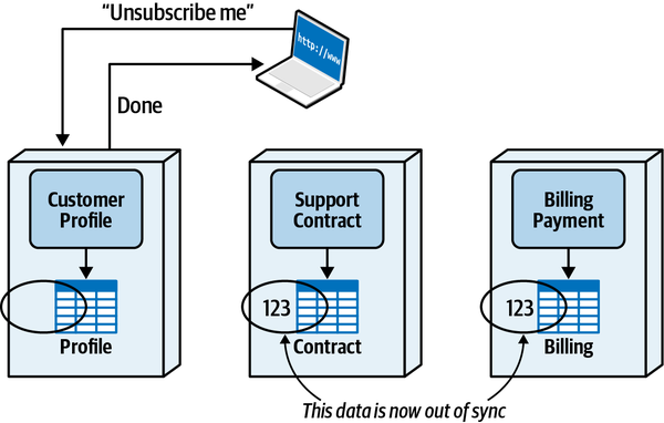
Figure 9-14. Data is out of sync after the customer unsubscribes from the support plan
We will use this scenario to describe each of the eventual consistency patterns for getting all of the data in sync for this atomic business request.
Background Synchronization Pattern
The background synchronization pattern uses a separate external service
One of the challenges of this pattern is that the background process used to keep all the data in sync must know what data has changed. This can be done through an event stream, a database trigger, or reading data from source tables and aligning target tables with the source data. Regardless of the technique used to identify changes, the background process must have knowledge of all the tables and data sources involved in the transaction.
Figure 9-15 illustrates the use of the background synchronization pattern for the Sysops Squad unregister example. Notice that at 11:23:00 the customer issues a request to unsubscribe from the support plan. The Customer Profile Service receives the request, removes the data, and one second later (11:23:01) responds back to the customer that they have been successfully unsubscribed from the system. Then, at 23:00 the background batch synchronization process starts. The background synchronization process detects that customer 123 has been removed either through event streaming or primary table versus secondary table deltas, and deletes the data from the Contract and Billing tables.
This pattern is good for overall responsiveness because the end user doesn’t have to wait for the entire business transaction to complete (in this case, unsubscribing from the support plan). But, unfortunately, some serious trade-offs with this eventual consistency pattern.
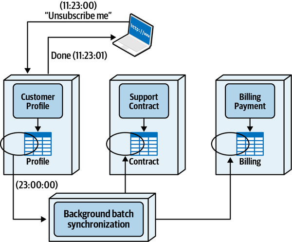
Figure 9-15. The background synchronization pattern uses an external process to ensure data consistency
The biggest disadvantage of the background synchronization pattern is that it couples all of the data sources together, thus breaking every bounded context between the data and the services. Notice in Figure 9-16 that the background batch synchronization process must have write access to each of the tables owned by the corresponding services, meaning that all of the tables effectively have shared ownership between the services and the background synchronization process.
This shared data ownership between the services and the background synchronization process is riddled with issues, and emphasizes the need for tight bounded contexts within a distributed architecture. Structural changes made to the tables owned by each service (changing a column name, dropping a column, and so on) must also be coordinated with an external background process, making changes difficult and time-consuming.
In addition to difficulties with change control, problems occur with regard to duplicated business logic as. In looking at Figure 9-15, it might seem fairly straightforward that the background process would simply perform a DELETE operation on all rows in the Contract and Billing tables containing customer 123. However, certain business rules may exist within these services for the particular operation.
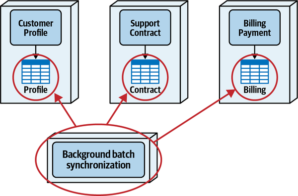
Figure 9-16. The background synchronization pattern is coupled to the data sources, therefore breaking the bounded context and data ownership
For example, when a customer unsubscribes, their existing support contracts and billing history are kept for three months in the event the customer decides to resubscribe to the support plan. Therefore, rather than deleting the rows in those tables, a remove_date column is set with a long value representing the date the rows should be removed (a zero value in this column indicates an active customer). Both services check the remove_date daily to determine which rows should be removed from their respective tables. The question is, where is that business logic located? The answer, of course, is in the Support Contract and Billing Payment Services—oh, and also the background batch process!
The background synchronization eventual consistency pattern is not suitable for distributed architectures requiring tight bounded contexts (such as microservices) where the coupling between data ownership and functionality is a critical part of the architecture. Situations where this pattern is useful are closed (self-contained) heterogeneous systems that don’t communicate with each other or share data.
For example, consider a contractor order entry system that accepts orders for building materials, and another separate system (implemented in a different platform) that does contractor invoicing. Once a contractor orders supplies, a background synchronization process moves those orders to the invoicing system to generate invoices. When a contractor changes an order or cancels it, the background synchronization process moves those changes to the invoicing system to update the invoices. This is a good example of systems becoming eventually consistent, with the contractor order always in sync between the two systems.
Table 9-5 summarizes the trade-offs for the background synchronization pattern for eventual consistency.
Orchestrated Request-Based Pattern
Unlike the previous background synchronization pattern or the event-based pattern described in the next section, the orchestrated request-based pattern attempts to process the entire distributed transaction during the business request, and therefore requires some sort of orchestrator to manage the distributed transaction. The orchestrator, which can be a designated existing service or a new separate service, is responsible for managing all of the work needed to process the request, including knowledge of the business process, knowledge of the participants involved, multicasting logic, error handling, and contract ownership.
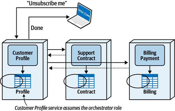
Figure 9-17. The Customer Profile Service takes on the role of an orchestrator for the distributed transaction
Although this approach avoids the need for a separate orchestration service, it tends to overload the responsibilities of the service designated as the distributed transaction orchestrator. In addition to the role of an orchestrator, the designated service managing the distributed transaction must perform its own responsibilities as well. Another drawback to this approach is that it lends itself to tight coupling and synchronous dependencies between services.
The approach we generally prefer when using the orchestrated request-based pattern is to use a dedicated orchestration service for the business request. This approach, illustrated in Figure 9-18, frees up the Customer Profile Service from the responsibility of managing the distributed transaction and places that responsibility on a separate orchestration service.
We will use this separate orchestration service approach to describe how this eventual consistency pattern works and the corresponding trade-offs with this pattern.
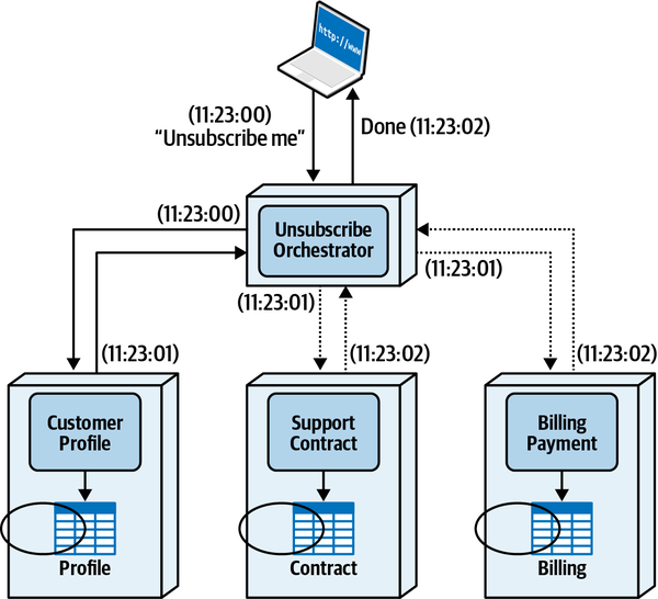
Figure 9-18. A dedicated orchestration service takes on the role of an orchestrator for the distributed transaction
Notice that at 11:23:00 the customer issues a request to unsubscribe from the Sysops Squad support plan. The request is received by the Unsubscribe Orchestrator Service, which then forwards the request synchronously to the Customer Profile Service to remove the customer from the Profile table. One second later, the Customer Profile Service sends back an acknowledgment to the Unsubscribe Orchestrator Service, which then sends parallel requests (either through threads or some sort of asynchronous protocol) to both the Support Contract and Billing Payment Services. Both of these services process the unsubscribe request, and then send an acknowledgment back one second later to the Unsubscribe Orchestrator Service indicating they are done processing the request. Now that all data is in sync, the Unsubscribe Orchestrator Service responds back to the client at 11:23:02 (two seconds after the initial request was made), letting the customer know they were successfully unsubscribed.
The first trade-off to observe is that the orchestration approach generally favors data consistency over responsiveness. Adding a dedicated orchestration service not only adds additional network hops and service calls, but depending on whether the orchestrator executes calls serially or in parallel, additional time is needed for the back-and-forth communication between the orchestrator and the services it’s calling.
Response time could be improved in Figure 9-18 by executing the Customer Profile request at the same time as the other services, but we chose to do that operation synchronously for error handling and consistency reasons. For example, if the customer could not be deleted from the Profile table because of an outstanding billing charge, no other action is needed to reverse the operations in the Support Contract and Billing Payment Services. This represents another example of consistency over responsiveness.
Besides responsiveness, the other trade-off with this pattern is complex error handling. While the orchestrated request-based pattern might seem straightforward, consider what happens when the customer is removed from the Profile table and Contract table, but an error occurs when trying to remove the billing information from the Billing table, as illustrated in Figure 9-19. Since the Profile and Support Contract Services individually committed their operations, the Unsubscribe Orchestrator Service must now decide what action to take while the customer is waiting for the request to be processed:
-
Should the orchestrator send the request again to the Billing Payment Service for another try?
-
Should the orchestrator perform a compensating transaction and have the Support Contract and Customer Profile Services reverse their update operations?
-
Should the orchestrator respond to the customer that an error occurred and to wait a bit before trying again, while trying to repair the inconsistency?
-
Should the orchestrator ignore the error in hopes that some other process will deal with the issue and respond to the customer that they have been successfully unsubscribed?
This real-world scenario creates a messy situation for the orchestrator. Because this is the eventual consistency pattern used, there is no other means to correct the data and get things back in sync (therefore negating options 3 and 4 in the preceding list). In this case,
remove_date column in the Contract table back to zero. This would require the orchestrator to have all of the necessary information to reinsert the customer, and that no side effects occur when creating a new customer (such as initializing the billing information or support contracts).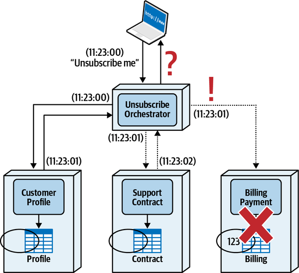
Figure 9-19. Error conditions are very hard to address when using the orchestrated request-based pattern
Table 9-6 summarizes the trade-offs for the orchestrated request-based pattern for eventual consistency.
Event-Based Pattern
customer unsubscribed) or command messages (such as unsubscribe customer) to a topic or event stream. Services involved in the distributed transaction listen for certain events and respond to those events.The eventual consistency time is usually short for achieving data consistency because of the parallel and decoupled nature of the asynchronous message processing. Services are highly decoupled from one another with this pattern, and responsiveness is good because the service triggering the eventual consistency event doesn’t have to wait for the data synchronization to occur before returning information to the customer.
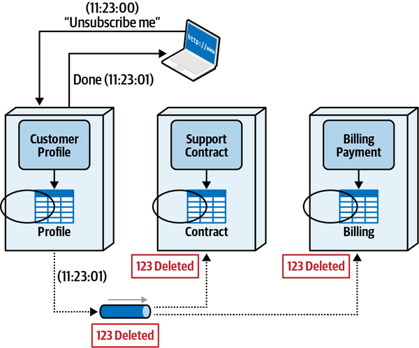
Figure 9-20. The event-based pattern uses asynchronous publish-and-subscribe messaging or event streams to achieve eventual consistency
For implementations using standard topic-based
Most message brokers will try a certain number of times to deliver a message,
Sysops Squad Saga: Data Ownership for Ticket Processing
Tuesday, January 18, 09:14
“No wonder nothing ever seems to work around here,” observed Sydney. “We’ve always had issues and arguments between us and the database team, and now I see the results of our company treating us as two separate teams.”
“Exactly,” said Addison. “I’m glad we are working more closely with the data team now. So, from what Dana said, the service that performs write actions on the data table owns the table, regardless of what other services need to access the data in a read-only manner. In that case, looks like the User Maintenance Service needs to own the data.”
Sydney agreed, and Addison created a general architecture decision record describing what to do for single-table ownership scenarios:
ADR: Single Table Ownership for Bounded Contexts
Context
When forming bounded contexts between services and data, tables must be assigned ownership to a particular service or group of services.Decision
When only one service writes to a table, that table will be assigned ownership to that service. Furthermore, services requiring read-only access to a table in another bounded context cannot directly access the database or schema containing that table.Per the database team, table ownership is defined as the service that performs write operations on a table. Therefore, for single table ownership scenarios, regardless of how many other services need to access the table, only one service is ever assigned an owner, and that owner is the service that maintains the data.
Consequences
Depending on the technique used, services requiring read-only access to a table in another bounded context may incur performance and fault-tolerance issues when accessing data in a different bounded context.
Now that Sydney and Addison better understood table ownership and how to form bounded contexts between the service and the data, they started to work on the survey functionality. The Ticket Completion Service would write the timestamp the ticket was completed and the expert who performed the job to the survey table. The Survey Service would write the timestamp the survey was sent to the customer, and also insert all of the survey results once the survey is received.
“This isn’t so hard now that I better understand bounded contexts and table ownership,” said Sydney.
“OK, let’s move on to the survey functionality,” said Addison.
“Oops,” said Sydney. “Both the Ticket Completion Service and the Survey Service write to the Survey table.”
“That’s what Dana called joint-table ownership,” said Addison.
“So, what are our options?” asked Sydney.
“Since splitting up the table won’t work, it really leaves us with only two options,” said Addison. “We can use a common data domain so that both services own the data, or we can use the delegate technique and assign only one service as the owner.”
“I like the common data domain. Let both services write to the table and share a common schema,” said Sydney.
“Except that won’t work in this scenario,” said Addison. “The Ticket Completion Service is already talking to the common ticketing data domain. Remember, a service can’t connect to multiple schemas.”
“Oh, right,” said Sydney. “Wait, I know, just add the survey tables to the ticketing data domain schema.”
“But now we are starting to combine all the tables back together.” said Addison. “Pretty soon we’ll be right back to a monolithic database again.”
“So what do we do?” asked Sydney.
“Wait, I think I see a good solution here,” said Addison. “You know how the Ticket Completion Service has to send a message to the Survey Service anyway to kick off the survey process once a ticket is complete? What if we passed in the necessary data along with that message so that the Survey Service can insert the data when it creates the customer survey?”
“That’s brilliant,” said Sydney. “That way, the Ticket Completion doesn’t need any access to the Survey table.”
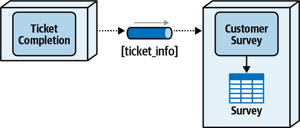
Figure 9-21. Survey Service owns the data using the delegation technique
ADR: Survey Service Owns the Survey Table
Context
Both the Ticket Completion Service and the Survey Service write to the Survey table. Because this is a joint ownership scenario, the alternatives are to use a common shared data domain or use the delegation technique. Table splitting is not an option because of the structure of the Survey table.Decision
The Survey Service will be the single owner of the Survey table, meaning it is the only service that can perform write operations to that table.Once a ticket is marked as complete and is accepted by the system, the Ticket Completion Service needs to send a message to the Survey Service to kick off the customer survey processing. Since the Ticket Completion Service is already sending a notification event, the necessary ticket information can be passed along with that event, thus eliminating the need for the Ticket Completion Service to have any access to the Survey table.
Consequences
All of the necessary data that the Ticket Completion Service needs to insert into the Survey table will need to be sent as part of the payload when triggering the customer survey process.In the monolithic system, the ticket completion inserted the survey record as part of the completion process. With this decision, the creation of the survey record is a separate activity from the ticket creation process and is now handled by the Survey Service.
Chapter 10. Distributed Data Access
Monday, January 3, 12:43
“Now that we’ve assigned ownership of the expert profile table to
“Can you modify the way the assignment algorithm works so that we can reduce the number of queries it needs?” asked Addison.
“Beats me,” replied Sydney. “Taylen’s the one who usually maintains those algorithms.”
Addison and Sydney met with Taylen to discuss the data access issue and to see if Taylen could modify the expert assignment algorithms to reduce the nimber of database calls to the expert profile table.
“Are you kidding me?” asked Taylen. “There’s no way I can rewrite the assignment algorithms to do what you are asking. Absolutely no way at all.”
“But our only other option is to make remote calls to the User Management Service every time the assignment algorithm needs expert data,” said Addison.
“What?” screamed Taylen. “We can’t do that!”
“That what I said as well,” said Sydney. “That means we are back to square one again. This distributed architecture stuff is hard. I hate to say this, but I am actually starting to miss the monolithic application. Wait, I know. What if we made messaging calls to the User Maintenance Service instead of using REST?”
“That’s the same thing,” said Taylen. “I still have to wait for the information to come back, whether we use messaging, REST, or any other remote access protocol. That table simply needs to be in the same data domain as the ticketing tables.”
“There’s got to be another solution to access data we no longer own,” said Addison. “Let me check with Logan.”
In most monolithic systems using a single database, developers don’t give a second thought to reading database tables. SQL table joins are commonplace, and with a simple query all necessary data can be retrieved in a single database call. However, when data is broken into separate databases or schemas owned by distinct services, data access for read operations starts to become hard.
This chapter describes the various ways services can gain read access to data they don’t own—in other words, outside the bounded context of the services needing the data. The four patterns of data access we discuss in this chapter include the Inter-service Communication pattern, Column Schema Replication pattern, Replicated Cache pattern, and the Data Domain pattern.
In this example, when a request is made from a customer to display in their wish list, both the item ID and and the item description (item_desc) are returned to the customer. However, the Wishlist Service does not have the item description in its table; that data is owned by the Catalog Service in a tightly formed bounded context providing change control and data ownership. Therefore, the architect must use one of the data access patterns outlined in this chapter to ensure the Wishlist Service can obtain the product descriptions from the Catalog Service.
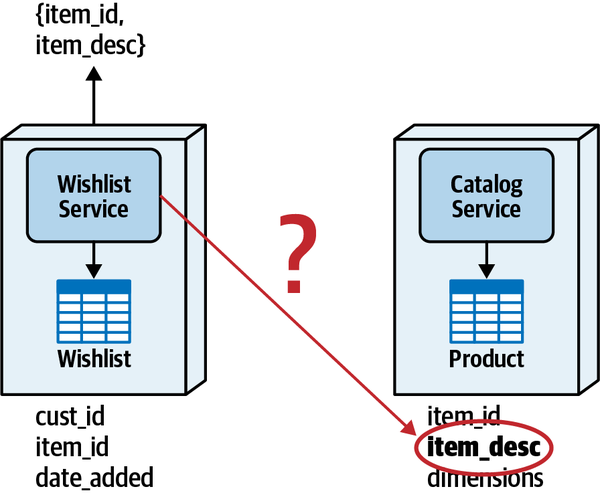
Figure 10-1. Wishlist Service needs item descriptions but doesn’t have access to the product table containing the data
Interservice Communication Pattern
The Interservice Communication pattern is by far the most
Notice that for every request to get a customer wish list, the Wishlist Service must make a remote call to the Catalog Service to get the item descriptions.
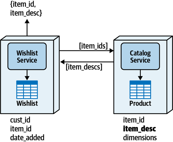
Figure 10-2. Interservice communication data access pattern
Column Schema Replication Pattern
item_desc column is added to the Wishlist table, making that data available to the Wishlist Service without having to ask the Catalog Service for the data. 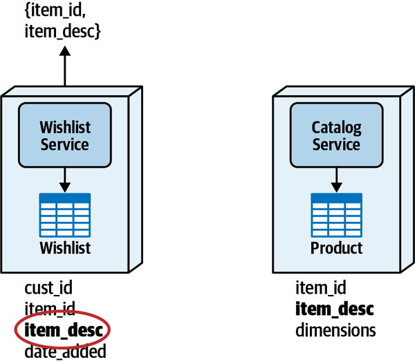
Figure 10-3. With the Column Schema Replication data access pattern, data is replicated to other tables
Data synchronization and data consistency are the two biggest issues associated with the Column Schema Replication data access pattern.
Even though the services are still coupled because of data synchronization, the service requiring read access has immediate access to the data, and can do simple SQL joins or queries to its own table to get the data. This increases performance, fault tolerance, and scalability, all things that were disadvantages with the interservice communication pattern.
While in general we caution against use of this data access pattern for scenarios such as the Wishlist Service and Catalog Service example, some situations where it might be a consideration are data aggregation, reporting, or situations where the other data access patterns are not a good fit because of large data volumes, high responsiveness requirements, or high-fault tolerance requirements.
Replicated Caching Pattern
Most developers and architects think of caching as a technique for increasing overall responsiveness.
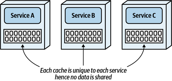
Figure 10-4. With a single in-memory cache, each service contains its own unique data
The other caching model used in distributed architectures is distributed caching. As illustrated in Figure 10-5, with this caching model, data is not held in-memory within each service, but rather held externally within a caching server. Services, using a proprietary protocol, make requests to the caching server to retrieve or update shared data. Note that unlike the single in-memory caching model, data can be shared among the services.
The distributed cache model is not an effective caching model to use for the replicated caching data access pattern for several reasons. First, there’s no benefit to the fault-tolerance issues found with the Interservice Communication pattern. Rather than depending on a service to retrieve data, the dependency has merely shifted to the caching server.
Because the cache data is centralized and shared, the distributed cache model allows other services to update data,
Lastly, since access to the centralized distributed cache is through a remote call, network latency adds additional retrieval time for the data, thus impacting overall responsiveness as compared to an in-memory replicated cache.
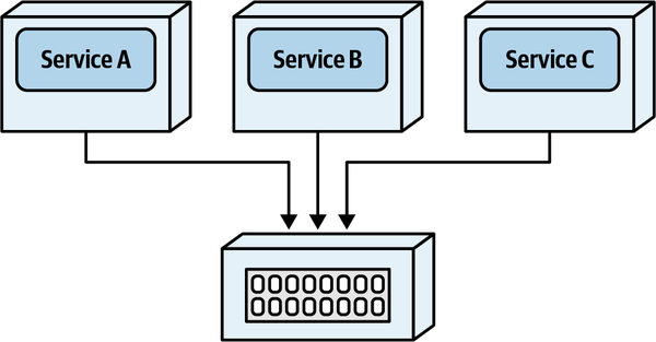
Figure 10-5. A distributed cache is external from the services
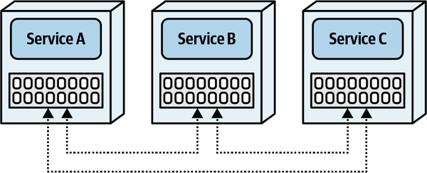
Figure 10-6. With a replicated cache, each service contains the same in-memory data
Not all caching products support replicated caching, so it’s important to check with the caching product vendor to ensure support for the replicated caching model.
To see how replicated caching can address distributed data access, we’ll return to our Wishlist Service and Catalog Service example. In Figure 10-7, the Catalog Service owns an in-memory cache of product descriptions (meaning it is the only service that can modify the cache), and the Wishlist Service contains a read-only in-memory replica of the same cache.
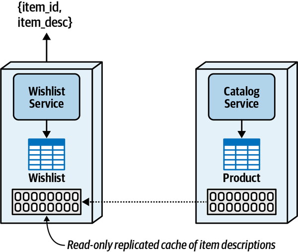
Figure 10-7. Replicated caching data access pattern
With this pattern, the Wishlist Service no longer needs to make calls to the Catalog Service to retrieve product descriptions—they’re already in-memory within the Wishlist Service. When updates are made to the product description by the Catalog Service, the caching product will update the cache in the Wishlist Service to make the data consistent.
The clear advantages of the replicated caching pattern are responsiveness, fault tolerance, and scalability. Because no explicit interservice communication is required between the services, data is readily available in-memory, providing the fastest possible access to data a service doesn’t own. Fault tolerance is also well supported with this pattern. Even if the Catalog Service goes down, the Wishlist Service can continue to operate. Once the Catalog Service comes back up, the caches connect to one another without any disruption to the Wishlist Service. Lastly, with this pattern, the Wishlist Service can scale independently from the Catalog Service.
With all these clear advantages, how could there possibly be a trade-off with this pattern? As the first law of software architecture states in our book, The Fundamentals of Software Architecture, everything in software architecture is a trade-off, and if an architect thinks they have discovered something that isn’t a trade-off, it means they just haven’t identified the trade-off yet.
The first trade-off with this pattern is a service dependency with regard to the cache data and startup timing. Since the Catalog Service owns the cache and is responsible for populating the cache, it must be running when the initial Wishlist Service starts up. If the Catalog Service is unavailable, the initial Wishlist Service must go into a wait state until a connection with the Catalog Service is established. Notice that only the initial Wishlist Service instance is impacted by this startup dependency; if the Catalog Service is down, other Wishlist instances can be started up, with the cache data transferred from one of the other Wishlist instances. It’s also important to note that once the Wishlist Service starts and has the data in the cache, it is not necessary for the Catalog Service to be available. Once the cache is made available in the Wishlist Service, the Catalog Service can come up and down without impacting the Wishlist Service (or any of its instances).
The second trade-off with this pattern is that of data volumes. If the volume of data is too high (such as exceeding 500 MB), the feasibility of this pattern diminishes quickly, particularly with regard to multiple instances of services needing the data. Each service instance has its own replicated cache, meaning that if the cache size of 500 MB and 5 instances of a service are required, the total memory used is 2.5 GB. Architects must analyze both the size of the cache and the total number of services instances needing the cached data to determine the total memory requirements for the replicated cache.
A third trade-off is that the replicated caching model usually cannot keep the data fully in sync between services if the rate of change of the data (update rate) is too high. This varies based on the size of the data and the replication latency, but in general this pattern is not well suited for highly volatile data (such as product inventory counts). However, for relatively static data (such as a product description), this pattern works well.
The last trade-off associated with this pattern is that of configuration and setup management. Services know about each other in the replicated caching model through TCP/IP broadcasts and lookups. If the TCI/IP broadcast and lookup range is too broad, it can take a long time to establish the socket-level handshake between services. Cloud-based and containerized environments make this particularly challenging because of the lack of control over IP addresses and the dynamic nature of IP addresses associated with these environments.
Table 10-3 lists the trade-offs associated with the replicated cache data access pattern.
Data Domain Pattern
Consider the Wishlist Service and Catalog Service problem again, where the Wishlist Service needs access to the product descriptions but does not have access to the table containing those descriptions. Suppose the Interservice Communication pattern is not a feasible solution because of reliability issues with the Catalog Service as well as the performance issues with network latency and the additional data retrieval. Also suppose using the Column Schema Replication pattern is not feasible because of the need for high levels of data consistency. Finally, suppose that the Replicated Cache pattern isn’t an option because of the high data volumes. The only other solution is to create a data domain, combining the Wishlist and Product tables in the same shared schema, accessible to both the Wishlist Service and the Catalog Service.
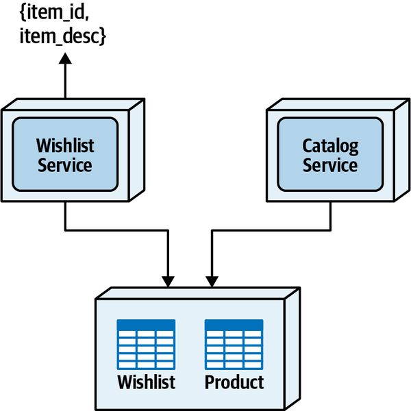
Figure 10-8. Data domain data access pattern
While the sharing of data is generally discouraged in a distributed architecture, this pattern has huge benefits over the other data access patterns. First of all, the services are completely decoupled from each other, thereby resolving any availability dependency, responsiveness, throughput, and scalability issues. Responsiveness is very good with this pattern because the data is available using a normal SQL call, removing the need to do additional data aggregations within the functionality of the service (as is required with the Replicated Cache pattern).
Both data consistency and data integrity rate very high with the Data Domain pattern. Since multiple services access the same data tables, data does not need to be transferred, replicated, or synchronized. Data integrity is preserved in this pattern in the sense that foreign-key constraints can now be enforced between the tables. In addition, other database artifacts, such as views, stored procedures, and triggers, can exist within the data domain. As a matter of fact, the preservation of these integrity constraints and database artifacts is another driver for the use of the Data Domain pattern.
With this pattern, no additional contracts are needed to
Table 10-4 lists trade-offs associated with the data domain data access pattern.
Sysops Squad Saga: Data Access for Ticket Assignment
Thursday, March 3, 14:59
“Unless we start consolidating all of these services, I guess we are stuck with the fact that the Ticket Assignment needs to somehow get to the expert profile data, and fast,” said Taylen.
“OK,” said Addison. “So service consolidation is out because these services are in entirely different domains, and the shared data domain option is out for the same reasons we talked about before—we cannot have the Ticket Assignment Service connecting to two different databases.”
“So, that leaves us with one of two choices.” said Sydney. “Either we use interservice communication or replicated caching.”
“Wait. Let’s explore the replicated caching option for a minute,” said Taylen. “How much data are we talking about here?”
“Well,” said Sydney, “we have 900 experts in the database. What data does the Ticket Assignment Service need from the expert profile table?”
“It’s mostly static information as we get the current expert location feeds from elsewhere. So, it would be the expert’s skill, their service location zones, and their standard scheduled availability,” said Taylen.
“OK, so that’s about 1.3 KB of data per expert. And since we have 900 experts total, that would be…about 1200 KB of data total. And the data is relatively static,” said Sydney.
“Hmm, that isn’t much data to store in memory,” said Taylen.
“Let’s not forget that if we used a replicated cache, we would have to take into account how many instances we would have for the User Management Service as well as the Ticket Assignment Service,” said Addison. “Just to be on the safe side, we should use the maximum number of instances of each we expect.”
“I’ve got that information,” said Taylen. “We expect to have only a maximum of two instances of the User Management Service, and a maximum of four at our highest peak for the Ticket Assignment Service.”
“That’s not much total in-memory data,” observed Sydney.
“No, it’s not,” said Addison. “OK, let’s analyze the trade-offs using the hypothesis-based approach we tried earlier. I suggest that we should go with the in-memory replicated cache option to cache only the data necessary for the Ticket Assignment Service. Any other trade-offs you can think of?”
Both Taylen and Sydney sat there for while trying to think of some negatives for the replicated cache approach.
“What if the User Management Service goes down?” asked Sydney.
“As long as the cache is populated, then the Ticket Assignment Service would be fine,” said Addison.
“Wait, you mean to tell me that the data would be in-memory, even if the User Management Service is unavailable?” asked Taylen.
“As long as the User Management Service starts before the Ticket Assignment Service, then yes,” said Addison.
“Ah!” said Taylen. “Then there’s our first trade-off. Ticket assignment cannot function unless the User Management Service is started. That’s not good.”
“But,” said Addison, “if we made remote calls to the User Management Service and it goes down, the Ticket Assignment Service becomes nonoperational. At least with the replicated cache option, once User Management is up and running, we are no longer dependent on it. So, replicated caching is actually more fault tolerant in this case.”
“True,” said Taylen. “We just have to be careful about the startup dependency.”
“Anything else you can think of as a negative?” asked Addison, knowing another obvious trade-off but wanting the development team to come up with it on their own.
“Um,” said Sydney, “yeah. I have one. What caching product are we going to use?”
“Ah,” said Addison, “that is in fact another trade-off. Have either of you done replicated caching before? Or anyone on the development team for that matter?”
Both Taylen and Sydney shook their heads.
“Then we have some risk here,” said Addison.
“Actually,” said Taylen, “I’ve been hearing a lot about this caching technique for a while and have been dying to try it out. I would volunteer to research some of the products and do some proof-of-concepts on this approach.”
“Great,” said Addison. “In the meantime, I will research what the licensing cost would be for those products as well, and if there’s any technical limitation with respect to our deployment environment. You know, things like availability zone crossovers, firewalls, that sort of stuff.”
The team began their research and proof-of-concept work, and found that this is indeed not only a feasible solution cost and effort wise, but would solve the issue of data access to the expert profile table. Addison discussed this approach with Logan, who approved the solution. Addison created an ADR outlining and justifying this decision.
ADR: Use of In-Memory Replicated Caching for Expert Profile Data
Context
The Ticket Assignment Service needs continuous access to the expert profile table, which is owned by the User Management Service in a separate bounded context. Access to the expert profile information can be done through interservice communication, in-memory replicated caching, or a common data domain.Decision
We will use replicated caching between the User Management Service and the Ticket Assignment Service, with the User Management Service being the sole owner for write operations.Because the Ticket Assignment Service already connects to the shared ticket data domain schema, it cannot connect to an additional schema. In addition, since the user management functionality and the core ticketing functionality are in two separate domains, we do not want to combine the data tables in a single schema. Therefore, using a common data domain is not an option.
Using an in-memory replicated cache resolves the performance and fault-tolerance issues associated with the interservice communication option.
Consequences
At least one instance of the User Management Service must be running when starting the first instance of the Ticket Assignment Service.Licensing costs for the caching product would be required for this option.
Chapter 11. Managing Distributed Workflows
Tuesday, February 15, 14:34
Austen bolted into Logan’s office just after lunch. “I’ve been looking
“Whoa, there, you maniac,” said Logan. “Where did you hear that? What gives you that impression?”
“Well, I’ve been reading a lot about microservices, and everyone’s advice seems to be to keep things highly decoupled. When I look at the patterns for communication, it seems that choreography is the most decoupled, so we should always use it, right?”
"Always is a tricky term in software architecture. I had a mentor who had a memorable perspective on this, who always said, Never use absolutes when talking about architecture, except when talking about absolutes. In other words, never say never. I can’t think of many decisions in architecture where always or never applies.”
“OK,” said Austen. “So how do architects decide between the different communication patterns?”
In Chapter 2, we identified three coupling forces when considering interaction models in distributed architectures:
Figure 11-1. The dimensions of dynamic quantum coupling
In this chapter, we discuss coordination: combining two or more
Orchestration is distinguished by the use of an orchestrator, whereas a choreographed solution does not use one.
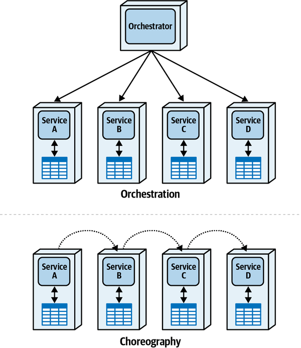
Figure 11-2. Orchestration versus choreography in distributed architectures
Orchestration Communication Style
The orchestration pattern uses an orchestrator (sometimes called a mediator) component
In this example, services A-D are domain services, each responsible for its own bounded context, data, and behavior. The Orchestrator component generally doesn’t include any domain behavior outside of the workflow it mediates.
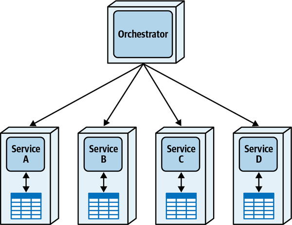
Figure 11-3. Orchestration among distributed microservices
Orchestration is useful when an architect must model a complex workflow that includes more than just the single “happy path,” but also alternate paths and error conditions. However, to understand the basic shape of the pattern, we start with the nonerror happy path. Consider a very simple example of Penultimate Electronics selling a device to one of its customers online, shown in Figure 11-4.
This system passes the Place Order request to the Order Placement Orchestrator, which makes a synchronous call to the Order Placement Service, which records the order and returns a status message. Next, the mediator calls the Payment Service, which updates payment information. Next, the orchestrator makes an asynchronous call to the Fulfillment Service to handle the order. The call is asynchronous because no strict timing dependencies exist for order fulfillment, unlike payment verification. For example, if order fulfillment happens only a few times a day, there is no reason for the overhead of a synchronous call. Similarly, the orchestrator then calls the Email Service to notify the user of a successful electronics order.
If the world consisted of only happy paths, software architecture would be easy. However, one of the primary hard parts of software architecture is error conditions and pathways.
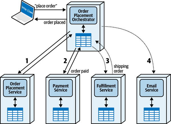
Figure 11-4. A “happy path” workflow using an orchestrator to purchase electronic equipment (note the asynchronous calls denoted by dotted lines for less time-sensitive calls)
Consider two potential error scenarios for electronics purchasing. First, what happens if the customer’s payment method is rejected? This error scenario appears in Figure 11-5.
Here, the Order Placement Orchestrator updates the order via the Order Placement Service as before. However, when trying to apply payment, it is rejected by the payment service, perhaps because of an expired credit card number. In that case, the Payment Service notifies the orchestrator, which then places a (typically) asynchronous call to send a message to the Email Service to notify the customer of the failed order. Additionally, the orchestrator updates the state of the Order Placement Service, which still thinks this is an active order.
Notice in this example we’re allowing each service to maintain its own transactional state, modeling our “Fairy Tale Saga(seo) Pattern”. One of the hardest parts of modern architectures is managing transactions, which we cover in Chapter 12.
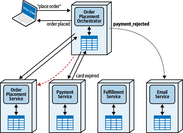
Figure 11-5. Payment rejected error condition
In the second error scenario, the workflow has progressed further along: what happens when the Fulfillment Service reports a back order? This error scenario appears in Figure 11-6.
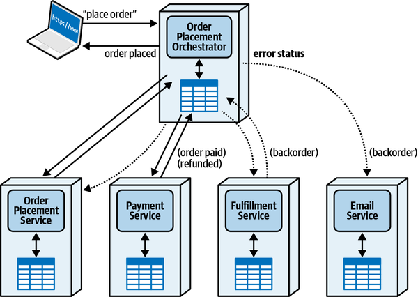
Figure 11-6. When an item is back-ordered, the orchestrator must rectify the state
As you can see, the workflow preceeds as normal until the Fulfillment Service notifies the orchestrator that the current item is out of stock, necessitating a back order. In that case, the orchestrator must refund the payment (this is why many online services don’t charge until shipment, not at order time) and update the state of the Order Placement Service.
One interesting characteristic to note in Figure 11-6: even in the most elaborate error scenarios, the architect wasn’t required to add additional communication paths that weren’t already there to facilitate the normal workflow, which differs from the “Choreography Communication Style”.
General advantages of the orchestration communication style include the following:
- Centralized workflow
-
As complexity goes up, having a unified component for state and behavior becomes beneficial.
- Error handling
-
Error handling is a major part of many domain workflows, assisted by having a state owner for the workflow.
- Recoverability
-
Because an orchestrator monitors the state of the workflow, an architect may add logic to retry if one or more domain services suffers from a short-term outage.
- State management
-
Having an orchestrator makes the state of the workflow queriable,
providing a place for other workflows and other transient states.
General disadvantages of the orchestration communication style include the following:
- Responsiveness
-
All communication must go through the mediator, creating a potential throughput bottleneck that can harm responsiveness.
- Fault tolerance
- While orchestration enhances recoverability for domain services,it creates a potential single point of failure for the workflow, which can be addressed with redundancy but adds more complexity.
- Scalability
- This communication style doesn’t scale as well as choreographybecause it has more coordination points (the orchestrator), which cuts down on potential parallelism. As we discussed inChapter 2, several dynamic coupling patterns utilize choreography and thus achieve higher scale (notably “Time Travel Saga(sec) Pattern” and “Anthology Saga(aec) Pattern”).
- Service coupling
-
Having a central orchestrator creates higher coupling between it and domain components, which is sometimes necessary. The orchestration communication style’s trade-offs appear in Table 11-1.
Choreography Communication Style
In this workflow, the initiating request goes to the first service in the chain of responsibility—in this case, the Order Placement Service. Once it has updated internal records about the order, it sends an asynchronous request that the Payment Service receives. Once payment has been applied, the Payment Service generates a message received by the Fulfillment Service, which plans for delivery and sends a message to the Email Service.
At first glance, the choreography solution seems simpler—fewer services (no orchestrator), and a simple chain of events/commands (messages). However, as with many issues in software architecture, the difficulties lie not with the default paths but rather with boundary and error conditions.
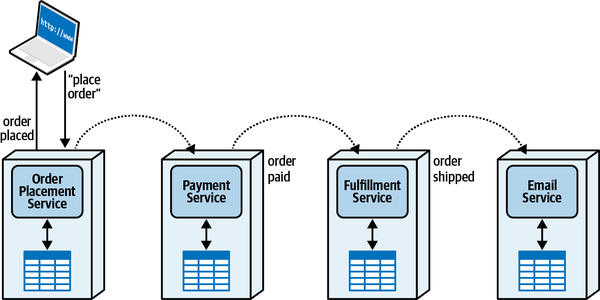
Figure 11-7. Purchasing electronics using choreography
As in the previous section, we cover two potential error scenarios. The first results from failed payment, as illustrated in Figure 11-8.
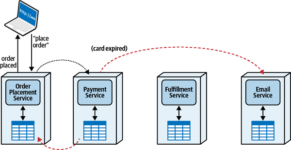
Figure 11-8. Error in payment in choreography
Rather than send a message intended for the Fulfillment Service, the Payment service sends messages indicating failure to the Email Service and back to the Order Placement Service to update the order status. This alternate workflow doesn’t appear too complex, with a single new communication link that didn’t exist before.
However, consider the increasing complexity imposed by the other error scenario for a product back order, shown in Figure 11-9.
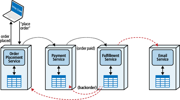
Figure 11-9. Managing the workflow error condition of product backlog
Many steps of this workflow have already completed before the event (out of stock) that causes the error. Because each of these services implement its own transactionality (this is an example of the “Anthology Saga(aec) Pattern”), when an error occurs, each service must issue compensating messages to other services. Once the Fulfillment Service realizes the error condition, it should generate events suited to its bounded context, perhaps a broadcast message subscribed to by the Email, Payment, and Order Placement services.
The example shown in Figure 11-9 illustrates the dependency between complex workflows and mediators. While the initial workflow in choreography illustrated in Figure 11-7 seemed simpler than Figure 11-4, the error case (and others) keeps adding more complexity to the choreographed solution. In Figure 11-10, each error scenario forces domain services to interact with each other, adding communication links that weren’t necessary for the happy path.
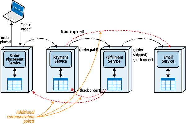
Figure 11-10. Error conditions in choreography typically add communication links
Every workflow that architects need to model in software has a certain amount
The semantic coupling of a workflow is mandated by the domain requirements of the solution and must be modeled somehow. However clever an architect is, they cannot reduce the amount of semantic coupling, but their implementation choices may increase it. This doesn’t mean that an architect might not push back on impractical or impossible semantics defined by business users—some domain requirements create extraordinarily difficult problems in architecture.
The architecture on the left represents the traditional layered architecture, separated by technical capabilities such as persistence, business rules, and so on. On the right, the same solution appears, but separated by domain concerns such as Catalog Checkout and Update Inventory rather than technical capabilities.
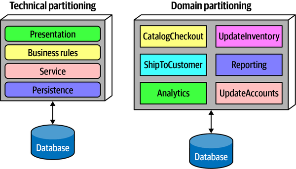
Figure 11-11. Technical versus domain partitioning in architecture
Both topologies are logical ways to organize a codebase. However, consider where domain concepts such as Catalog Checkout reside within each architecture, illustrated in Figure 11-12.
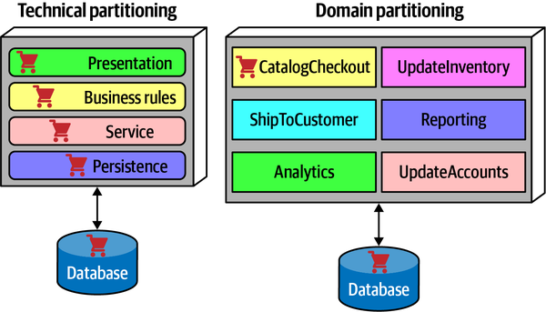
Figure 11-12. Catalog Checkout is smeared across implementation layers in a technically partitioned architecture
Catalog Checkout is “smeared” across the layers of the technical architecture, whereas it appears only in the matching domain component and database in the domain partitioned example. Of course, aligning a domain with domain partitioned architecture isn’t a revelation—one of the insights of domain-driven design was the primacy of the domain workflows. No matter what, if an architect wants to model a workflow, they must make those moving parts work together. If the architect has organized their architecture the same as the domains, the implementation of the workflow should have similar complexity.
Sometimes the extra complexity is warranted. For example, many layered architectures came from a desire by architects to gain cost savings by consolidating on architecture patterns, such as database connection pooling. In that case, an architect considered the trade-offs of the cost saving associated with technically partitioning database connectivity versus the imposed complexity and cost won in many cases.
The major lesson of the last decade of architecture design is to model the semantics of the workflow as closely as possible with the implementation.
Tip
An architect can never reduce semantic coupling via implementation, but they can make it worse.
Thus, we can establish a relationship between the semantic coupling and the need for coordination—the more steps required by the workflow, the more potential error and other optional paths appear.
Workflow State Management
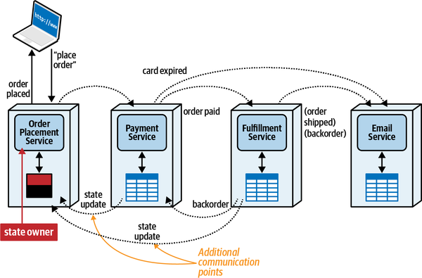
Figure 11-13. In choreography, a Front Controller is a domain service that owns workflow state in addition to domain behavior
In this scenario, some services must communicate back to the Order Placement Service to update the state of the order, as it is the state owner. While this simplifies the workflow, it increases communication overhead and makes the Order Placement Service more complex than one that handled only domain behavior. While the Front Controller pattern has some advantageous characteristics, it also has trade-offs, as shown in Table 11-2.
A second way for an architect to manage the transactional state is to keep no transient workflow state at all,
A third solution utilizes stamp coupling (described in more detail in “Stamp Coupling for Workflow Management”),
In Chapter 13, we discuss how contracts can reduce or increase workflow coupling in choreographed solutions.
Advantages of the choreography communication style include the following:
- Responsiveness
-
This communication style has fewer single choke points, thus offering more opportunities for parallelism.
- Scalability
-
Similar to responsiveness, lack of coordination points like orchestrators allows more independent scaling.
- Fault tolerance
- The lack of a single orchestrator allows an architect to enhance fault tolerance with the use of multiple instances.
- Service decoupling
-
No orchestrator means less coupling.
Disadvantages of the choreography communication style include the following:
- Distributed workflow
-
No workflow owner makes error management and other boundary conditions more difficult.
- State management
-
No centralized state holder hinders ongoing state management.
- Error handling
-
Error handling becomes more difficult without an orchestrator because the domain services must have more workflow knowledge.
- Recoverability
-
Similarly, recoverability becomes more difficult without an orchestrator to attempt retries and other remediation efforts.
Trade-Offs Between Orchestration and Choreography
State Owner and Coupling
However, as workflow complexity goes up, the need for an orchestrator rises proportionally, as illustrated in Figure 11-14.
In addition, the more semantic complexity contained in a workflow, the more utilitarian an orchestrator is. Remember, implementation coupling can’t make semantic coupling better, only worse.
Ultimately, the sweet spot for choreography lies with workflows that need responsiveness and scalability, and either don’t have complex error scenarios or they are infrequent. This communication style allows for high throughput; it is used by the dynamic coupling patterns “Phone Tag Saga(sac) Pattern”, “Time Travel Saga(sec) Pattern”, and “Anthology Saga(aec) Pattern”. However, it can also lead to extremely difficult implementations when other forces are mixed in, leading to the “Horror Story(aac) Pattern”.
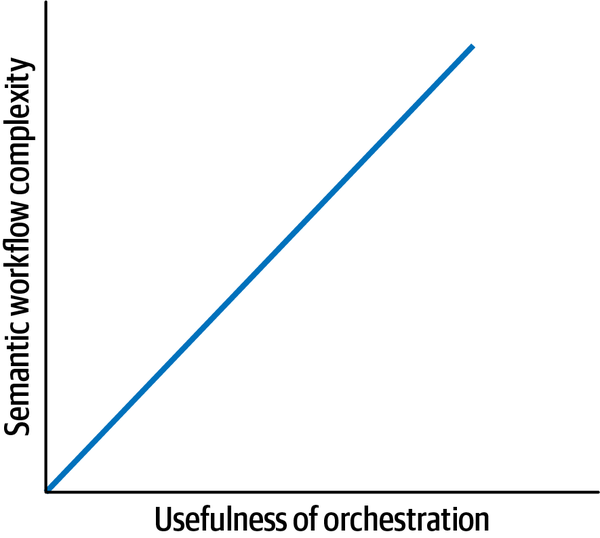
Figure 11-14. As the complexity of the workflow rises, orchestration becomes more useful
On the other hand, orchestration is best suited for complex workflows that include boundary and error conditions. While this style doesn’t provide as much scale as choreography, it greatly reduces complexity in most cases. This communication style appears in “Epic Saga(sao) Pattern”, “Fairy Tale Saga(seo) Pattern”, “Fantasy Fiction Saga(aao) Pattern”, and “Parallel Saga(aeo) Pattern”.
Coordination is one of the primary forces that create complexity for architects when determining how to best communicate between microservices. Next, we investigate how this force intersects with another primary force, consistency.
Sysops Squad Saga: Managing Workflows
Thursday, March 15, 11:00
Addison and Austen arrived at Logan’s office right on time, armed with a presentation and ritual coffee urn from the kitchen.
“Are you ready for us?” asked Addison.
“Sure,” said Logan. “Good timing—just got off a conference call. Are y’all ready to talk about workflow options for the primary ticket flow?”
“Yes!” said Austen. “I think we should use choreography, but Addison thinks orchestration, and we can’t decide.”
“Give me an overview of the workflow we’re looking at.”
“It’s the primary ticket workflow,” said Addison. “It involves four services; here are the steps.”
Customer-facing operations
-
Customer submits a trouble ticket through the Ticket Management Service and receives a ticket number.
Background operations
-
The Ticket Assignment Service finds the right Sysops expert for the trouble ticket.
-
The Ticket Assignment Service routes the trouble ticket to the systems expert’s mobile device.
-
The customer is notified via the Notification Service that the Sysops expert is on their way to fix the problem.
-
The expert fixes the problem and marks the ticket as complete, which is sent to the Ticket Management Service.
-
The Ticket Management Service communicates with the Survey Service to tell the customer to fill out the survey.
“Have you modeled both solutions?” asked Logan.
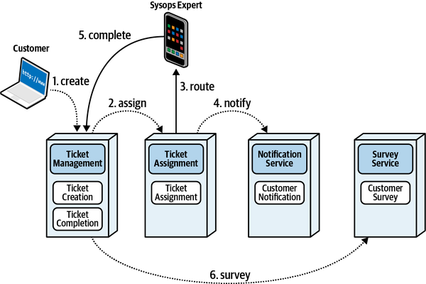
Figure 11-15. Primary ticket flow modeled as choreography
“…and the model for orchestration is in Figure 11-16.”
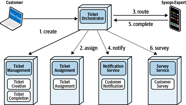
Figure 11-16. Primary ticket workflow modeled as orchestration
Logan pondered the diagrams for a moment, then pronounced, “Well, there doesn’t seem to be an obvious winner here. You know what that means.”
Austen piped up, “Trade-offs!”
“Of course,” laughed Logan. " Let’s think about the likely scenarios and see how each solution reacts to them. What are the primary issues you are concerned with?”
“The first is lost or misrouted tickets. The business has been complaining about it, and it has become a priority,” said Addison.
“OK, which handles that problem better—orchestration or choreography?”
“Easier control of the workflow sounds like the orchestrator version is better—we can handle all the workflow issues there,” volunteered Austen.
“OK, let’s build a table of issues and preferred solutions in Table 11-6.”
“What’s the next issue we should model?” Addison asked.
“We need to know the status of a trouble ticket at any given moment—the business has requested this feature, and it makes it easier to track several metrics. That implies we need an orchestrator so that we can query the state of the workflow.”
“But you don’t have to have an orchestrator for that—we can query any given service to see if it has handled a particular part of the workflow, or use stamp coupling,” said Addison.
“That’s right—this isn’t a zero-sum game,” said Logan. “It’s possible that both or neither work just as well. We’ll give both solutions credit in our updated table in Table 11-7.”
“OK, what else?”
“Just one more that I can think of,” Addison said. “Tickets can get canceled by the customer, and tickets can get reassigned because of expert availability, lost connections to the expert’s mobile device, or expert delays at a customer site. Therefore, proper error handling is important. That means orchestration?”
“Yes, generally. Complex workflows must go somewhere, either in an orchestrator or scattered through services. It’s nice to have a single place to consolidate error handling. And choreography definitely does not score well here, so we’ll update our table in Table 11-8.”
“That looks pretty good. Any more?”
“Nothing that’s not obvious,” said Addison. “We’ll write this up in an ADR; in case we think of any other issues, we can add them there.”
ADR: Use Orchestration for Primary Ticket Workflow
Context
For the primary ticket workflow, the architecture must support easy tracking of lost or mistracked messages, excellent error handling, and the ability to track ticket status. Either an orchestration solution illustrated in Figure 11-16 or a choreography solution illustrated in Figure 11-15 will work.Decision
We will use orchestration for the primary ticketing workflow.We modeled orchestration and choreography and arrived at the trade-offs in Table 11-8.
Consequences
Ticketing workflow might have scalability issues around a single orchestrator, which should be reconsidered if current scalability requirements change.
Chapter 12. Transactional Sagas
Thursday, March 31, 16:55
Austen showed up at Logan’s office late on a windy Thursday afternoon. “Addison just sent me over here to ask you about some horror story?”
Logan stopped and looked up. “Is that a description of whatever crazy extreme sport you’re doing this weekend? What is it this time?”
“It’s late spring, so a bunch of us are going ice skating on the thawing lake. We’re wearing body suits, so it’s really a combination of skating and swimming. But that’s not what Addison meant at all. When I showed Addison my design for the Ticketing workflow, I was immediately instructed to come to you and tell you I’ve created a horror story.”
Logan laughed. “Oh, I see what’s going on—you stumbled into the Horror Story saga communication pattern. You designed a workflow with asynchronous communication, atomic transactionality, and choreography, right?”
“How did you know?”
“That’s the Horror Story saga pattern, or really, anti-pattern. There are eight generic saga patterns we start from, so it’s good to know what they are, because each has a different balance of trade-offs.”
However, recall from Chapter 2 that this is only one of eight possible types of sagas. In this section, we dive much deeper and look at the inner workings of transactional sagas and how to manage them, particularly when errors occur. After all, since distributed transactions lack atomicity (see “Distributed Transactions”), what makes them interesting is when problems occur.
Transactional Saga Patterns
In Chapter 2, we introduced a matrix that juxtaposed each
| Pattern name | Communication | Consistency | Coordination |
|---|---|---|---|
Epic Saga(sao) | Synchronous | Atomic | Orchestrated |
Phone Tag Saga(sac) | Synchronous | Atomic | Choreographed |
Fairy Tale Saga(seo) | Synchronous | Eventual | Orchestrated |
Time Travel Saga(sec) | Synchronous | Eventual | Choreographed |
Fantasy Fiction Saga(aao) | Asynchronous | Atomic | Orchestrated |
Horror Story(aac) | Asynchronous | Atomic | Choreographed |
Parallel Saga(aeo) | Asynchronous | Eventual | Orchestrated |
Anthology Saga(aec) | Asynchronous | Eventual | Choreographed |
We provide whimsical names for each combination, all derived from types of sagas. However, the pattern names exist to help differentiate the possibilities, and we don’t want to provide a memorization test to associate a pattern name to a set of characteristics, so we have added a superscript to each saga type indicating the values of the three dimensions listed in alphabetical order (as in Table 12-1). For example, the Epic Saga(sao) pattern indicates the values of synchronous, atomic, and orchestrated for communication, consistency, and coordination. The superscripts help you associate names to character sets more easily.
While architects will utilize some of the patterns more than others, they all have legitimate uses and differing sets of trade-offs.
We illustrate each possible communication combination with both a
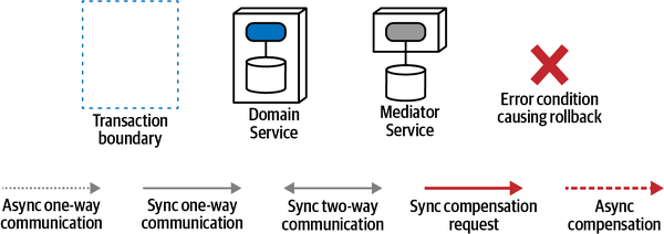
Figure 12-1. Legend for ISO architecture interaction diagrams
For each of the architecture patterns, we do not show every possible interaction, which would become repetitive. Instead, we identify and illustrate the differentiating features of the pattern—what makes its behavior unique among the patterns.
Epic Saga(sao) Pattern
This type of communication is the “traditional” saga pattern as many
This pattern utilizes synchronous communication, atomic consistency, and orchestrated coordination. The architect’s goal when choosing this pattern mimics the behavior of monolithic systems—in fact, if a monolithic system were added to this diagram in Figure 12-2, it would be the origin (0, 0, 0), lacking distribution entirely. Thus, this communication style is most familiar with architects and developers of traditional transactional systems.
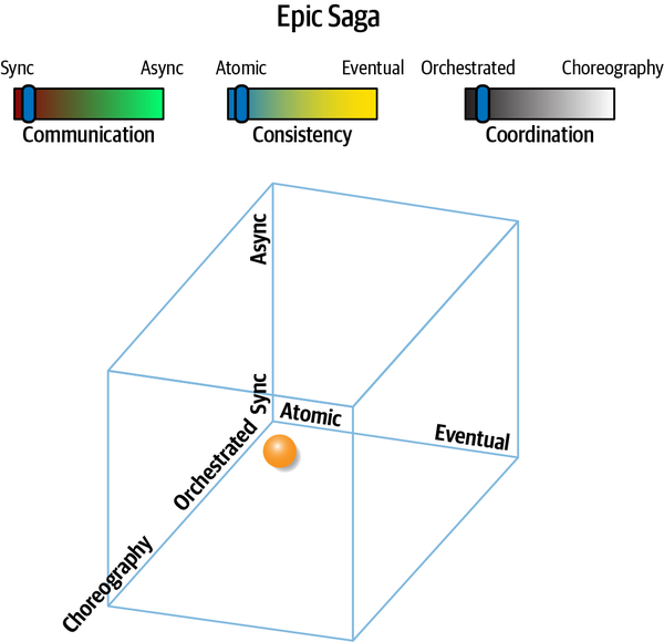
Figure 12-2. The Epic Saga(sao) pattern’s dynamic coupling (communication, consistency, coordination) relationships
The isomorphic representation of the Epic Saga(sao) pattern appears in Figure 12-3.
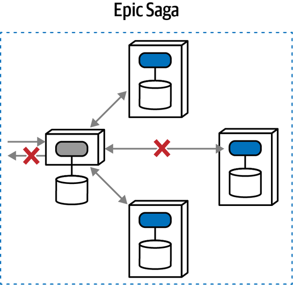
Figure 12-3. The isomorphic communication illustration of the Epic Saga(sao) pattern
Here, an orchestrator service orchestrates a workflow that includes updates for three services, expected to occur transactionally—either all three calls succeed or none do. If one of the calls fails, they all fail and return to the previous state. An architect can solve this coordination problem in a variety of ways, all complex in distributed architectures. However, such transactions limit the choice of databases and have legendary failure modes.
Many nascent or naive architects trust that, because a pattern exists for a problem, it represents a clean solution. However, the pattern is recognition of only commonality, not solvability.
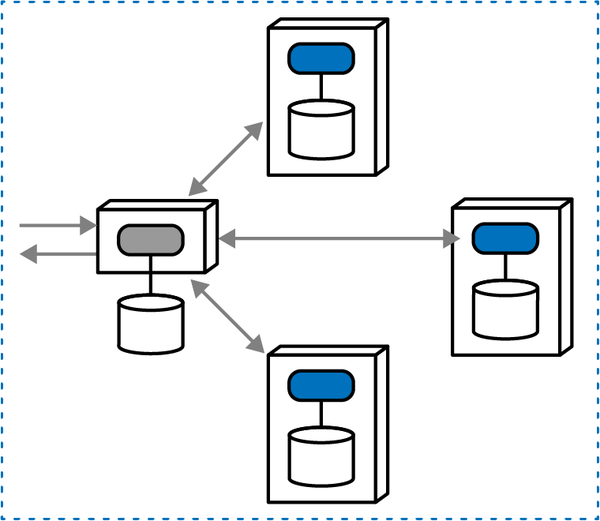
Figure 12-4. A successful orchestrated transactional Epic Saga using a compensating transaction
However, as with many things in architecture, the error conditions cause the difficulties. In a compensating transaction framework, the mediator monitors the success of calls, and issues compensating calls to other services if one or more of the requests fail, as shown in Figure 12-5.
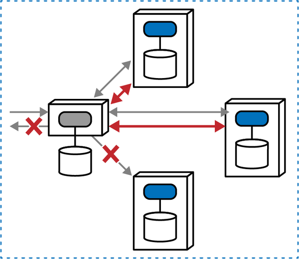
Figure 12-5. When an error occurs, a mediator must send compensating requests to other services
A mediator both accepts requests and mediates the workflow, and synchronous calls to the first two services succeed. However, when trying to make the call to the last service, it fails (from a possibly a wide variety of both domain and operational reasons). Because the goal of the Epic Saga(sao) is atomic consistency, the mediator must utilize compensating transactions and request that the other two services undo the operation from before, returning the overall state to what it was before the transaction started.
This pattern is widely used: it models familiar behavior, and it has a well-established pattern name. Many architects default to the Epic Saga(sao) pattern because it feels familiar to monolithic architectures, combined with a request (sometimes demand) from stakeholders that state changes must synchronize, regardless of technical constraints. However, many of the other dynamic quantum coupling patterns may offer a better set of trade-offs.
The clear advantage of the Epic Saga(sao) is the transactional coordination that mimics monolithic systems, coupled with the clear workflow owner represented via an orchestrator. However, the disadvantages are varied. First, orchestration plus transactionality may have an impact on operational architecture characteristics such as performance, scale, elasticity, and so on—the orchestrator must make sure that all participants in the transaction have succeeded or failed, creating timing bottlenecks. Second, the various patterns used to implement distributed transactionality (such as compensating transactions) succumb to a wide variety of failure modes and boundary conditions, along with adding inherent complexity via undo operations. Distributed transactions present a host of difficulties and thus are best avoided if possible.
The Epic Saga(sao) pattern features the following characteristics:
- Coupling level
-
This pattern exhibits extremely high levels of coupling across all possible dimensions: synchronous communication, atomic consistency, and orchestrated coordination—it is in fact the most highly coupled pattern in the list. This isn’t surprising, as it models the behavior of highly coupled monolithic system communication, but creates a number of issues in distributed architectures.
- Complexity level
-
Error conditions and other intensive coordination added to the requirement of atomicity add complexity to this architecture. The synchronous calls this architecture uses mitigate some of the complexity, as architects don’t have to worry about race conditions and deadlocks during calls.
- Responsiveness/availability
-
Orchestration creates a bottleneck, especially when it must also coordinate transactional atomicity, which reduces responsiveness. This pattern uses synchronous calls, further impacting performance and responsiveness. If any of the services are not available or an unrecoverable error occurs, this pattern will fail.
- Scale/elasticity
-
Similar to responsiveness, the bottleneck and coordination required to implement this pattern make scale and other operational concerns difficult.
While the Epic Saga(sao) is popular because of familiarity, it creates a number of challenges, both from a design and operational characteristics standpoint, as shown in Table 12-2.
| Epic Saga(sao) pattern | Ratings |
|---|---|
Communication | Synchronous |
Consistency | Atomic |
Coordination | Orchestrated |
Coupling | Very high |
Complexity | Low |
Responsiveness/availability | Low |
Scale/elasticity | Very low |
Fortunately, architects need not default to patterns that, while seemingly familiar, create accidental complexity—a variety of other patterns exist with differing sets of trade-offs. Refer to the “Sysops Squad Saga: Atomic Transactions and Compensating Updates” for a concrete example of the Epic Saga(sao) and some of the complex challenges it presents (and how to address those challenges).
Phone Tag Saga(sac) Pattern
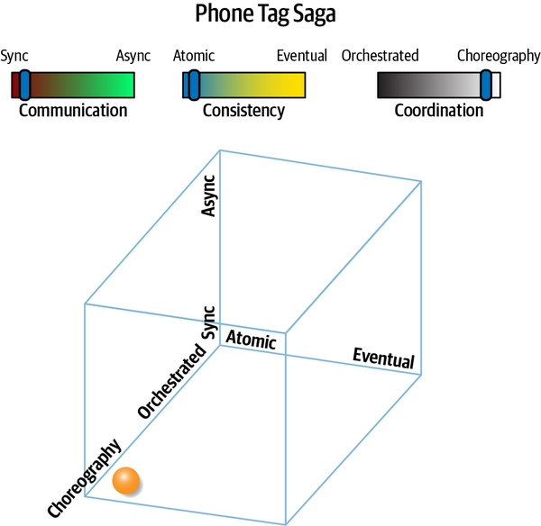
Figure 12-6. The Phone Tag pattern utilizes loosely coupled communication
The pattern name is Phone Tag because it resembles a well-known children’s game known as Telephone in North America: children form a circle, and one person whispers a secret to the next person, who passes it along to the next, until the final version is spoken by the last person. In Figure 12-6, choreography is favored over orchestration, creating the corresponding change in the structural communication shown in Figure 12-7.
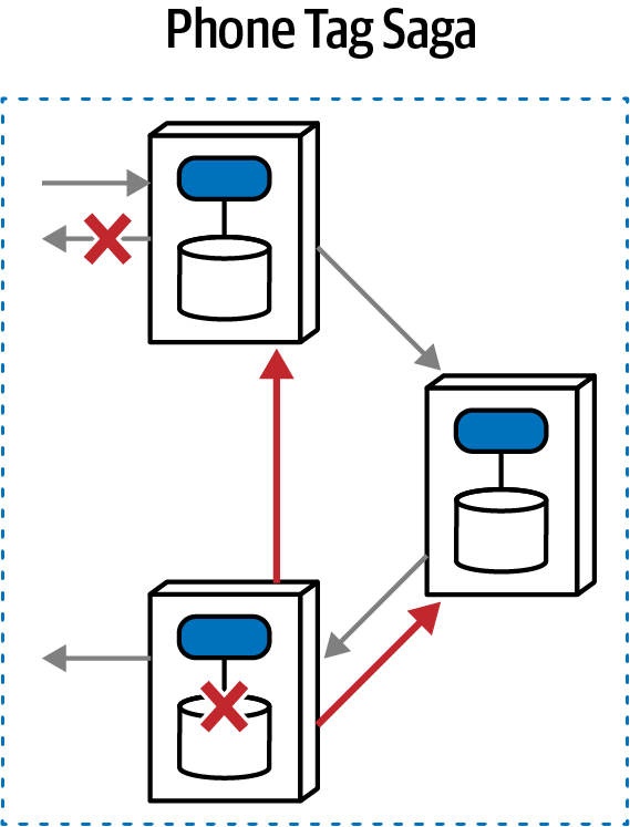
Figure 12-7. Because of a lack of orchestration, each participant must coordinate status
The Phone Tag Saga(sac) pattern features atomicity but also choreography, meaning that the architect designates no formal orchestrator. Yet atomicity requires some degree of coordination. In Figure 12-7, the initially called service becomes the coordination point (sometimes called the front controller). Once it has finished its work, it passes a request on to the next service in the workflow, which continues until the workflow succeeds. However, if an error condition occurs, each service must have built-in logic to send compensating requests back along the chain.
Because the architectural goal is transactional atomicity, logic to coordinate that atomicity must reside somewhere. Thus, domain services must contain more logic about the workflow context they participate within, including error handling and routing. For complex workflows, the front controller in this pattern will become as complex as most mediators, reducing the appeal and applicability of this pattern. Thus, this pattern is commonly used for simple workflows that need higher scale, but with a potential performance impact.
How does choreography versus orchestration improve operational architecture characteristics like scale?
Generally, the Phone Tag Saga(sac) offers slightly better scale than the Epic Saga(sao) because of the lack of a mediator, which can sometimes become a limiting bottleneck. However, this pattern also features lower performance for error conditions and other workflow complexities—without a mediator, the workflow must be resolved via communication between services, which impacts performance.
With the improved scalability brought about because of a lack of orchestration comes the increased complexity of the domain services to manage the workflow concerns in addition to their nominal responsibility. For complex workflows, increased complexity and interservice communication may drive architects back toward orchestration and its trade-offs.
The Phone Tag Saga(sac) has a fairly rare combination of features—generally, if an architect chooses choreography, they also choose asynchronicity. However, in some cases where an architect might choose this combination instead: synchronous calls ensure that each domain service completes its part of the workflow before invoking the next, eliminating race conditions. If error conditions are easy to resolve, or domain services can utilize idempotence and retries, then architects can build higher parallel scale using this pattern compared to an Epic Saga(sao).
The Phone Tag Saga(sac) pattern has the following characteristics:
- Coupling level
-
This pattern relaxes one of the coupling dimensions of the Epic Saga(sao) pattern, utilizing a choreographed rather than orchestrated workflow. Thus, this pattern is slightly less coupled, but with the same transactional requirement, meaning that the complexity of the workflow must be distributed between the domain services.
- Complexity level
- This pattern is significantly more complex than the Epic Saga(sao); complexity in this pattern rises linearly proportionally to the semantic complexity of the workflow: the more complex the workflow, the more logic must appear in each service to compensate for lack of orchestrator.Alternatively, an architect might add workflow information to the messages themselves as a form of stamp coupling (see“Stamp Coupling for Workflow Management”) to maintain state but adding to the overhead context required by each service.
- Responsiveness/availability
-
Less orchestration generally leads to better responsiveness, but error conditions in this pattern become more difficult to model without an orchestrator, requiring more coordination via callbacks and other time-consuming activities.
- Scale/elasticity
-
Lack of orchestration translates to fewer bottlenecks, generally increasing scalability, but only slightly. This pattern still utilizes tight coupling around two of the three dimensions, so scalability isn’t a highlight, especially if error conditions are common.
The ratings for the Phone Tag Saga(sac) appear in Table 12-3.
| Phone Tag Saga(sac) | Ratings |
|---|---|
Communication | Synchronous |
Consistency | Atomic |
Coordination | Choreographed |
Coupling | High |
Complexity | High |
Responsiveness/availability | Low |
Scale/elasticity | Low |
The Phone Tag Saga(sac) pattern is better for simple workflows that don’t have many common error conditions. While it offers a few better characteristics than the Epic Saga(sao), the complexity introduced by lack of an orchestrator offsets many of the advantages.
Fairy Tale Saga(seo) Pattern
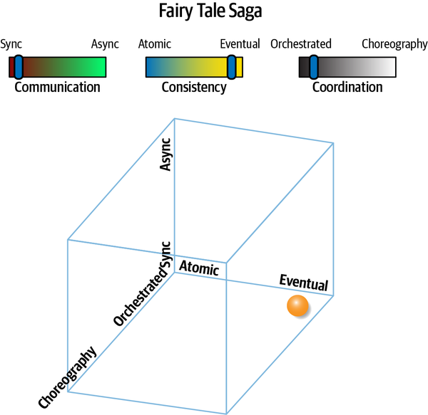
Figure 12-8. The Fairy Tale Saga(seo) illustrates eventual consistency
This communication pattern relaxes the difficult atomic requirement, providing many more options for architects to design systems. For example, if a service is down temporarily, eventual consistency allows for caching a change until the service restores. The communication structure for the Fairy Tale Saga(seo) is illustrated in Figure 12-9.
In this pattern, an orchestrator exists to coordinate request, response, and error handling. However, the orchestrator isn’t responsible for managing transactions, which each domain service retains responsibility for (for examples of common workflows, see Chapter 11). Thus the orchestrator can manage compensating calls, but without the requirement of occurring within an active transaction.
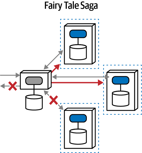
Figure 12-9. Isomorphic illustration of a Fairy Tale interaction
This is a much more attractive pattern and appears commonly in many microservices architectures. Having a mediator makes managing workflows easier, synchronous communication is the easier of the two choices, and eventual consistency removes the most difficult coordination challenge, especially for error handling.
The biggest appealing advantage of the Fairy Tale Saga(seo) is the lack of holistic transactions. Each domain service manages its own transactional behavior, relying on eventual consistency for the overall workflow.
Compared to many other patterns, this pattern generally exhibits a good balance of trade-offs:
- Coupling level
-
The Fairy Tale Saga(seo) features high coupling, with two of the three coupling drivers maximized in this pattern (synchronous communication and orchestrated coordination). However, the worse driver of coupling complexity—transactionality—disappears in this pattern in favor of eventual consistency. The orchestrator must still manage complex workflows, but without the stricture of doing so within a transaction.
- Complexity level
-
Complexity for the Fairy Tale Saga(seo) is quite low; it includes the most convenient options (orchestrated, synchronicity) with the loosest restriction (eventual consistency). Thus the name Fairy Tale Saga(seo)—a simple story with a happy ending.
- Responsiveness/availability
-
Responsiveness is typically better in communication styles of this type because, even though the calls are synchronous, the mediator needs to contain less time-sensitive state about ongoing transactions, allowing for better load balancing. However, true distinctions in performance come with asynchronicity, illustrated in future patterns.
- Scale/elasticity
-
Lack of coupling generally leads to higher scale; removing transactional coupling allows each service to scale more independently.
The ratings for the Fairy Tale Saga(seo) appear in Table 12-4.
| Fairy Tale Saga(seo) | Ratings |
|---|---|
Communication | Synchronous |
Consistency | Eventual |
Coordination | Orchestrated |
Coupling | High |
Complexity | Very low |
Responsiveness/availability | Medium |
Scale/elasticity | High |
If an architect can take advantage of eventual consistency, this pattern is quite attractive, combining the easy moving parts with the fewest scary restrictions, making it a popular choice among architects.
Time Travel Saga(sec) Pattern
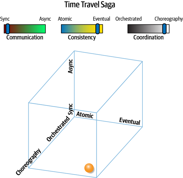
Figure 12-10. The Time Travel Saga(sec) pattern uses two of three decoupling techniques
The structural topology illustrates the lack of orchestration, shown in Figure 12-11.
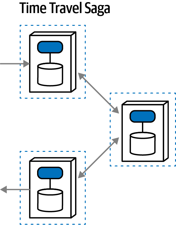
Figure 12-11. Complex workflows become difficult to manage without orchestration
In this workflow, each service accepts a request, performs an action, and then forwards the request on to another service.
The lack of transactions in the Time Travel Saga(sec) pattern makes workflows easier to model; however, the lack of an orchestrator means that each domain service must include most workflow state and information. As in all choreographed solutions, a direct correlation exists between workflow complexity and the utility of an orchestrator; thus, this pattern is best suited for simple workflows.
For solutions that benefit from high throughput, this pattern works extremely well for “fire and forget” style workflows, such as electronic data ingestion, bulk transactions, and so on. However, because no orchestrator exists, domain services must deal with error conditions and coordination.
Lack of coupling increases scalability with this pattern; only adding asynchronicity would make it more scalable (as in the Anthology Saga(aec) pattern). However, because this pattern lacks holistic transactional coordination, architects must take extra effort to synchronize data.
Here is the qualitative evaluation of the Time Travel Saga(sec) pattern:
- Coupling level
-
The coupling level falls in the medium range with the Time Travel Saga(sec), with the decreased coupling brought on by the absence of an orchestrator balanced by the still remaining coupling of synchronous communication. As with all eventual consistency patterns, the absence of transactional coupling eases many data concerns.
- Complexity level
-
The loss of transactionality provides a decrease in complexity for this pattern. This pattern is quasi-special-purpose, superbly suited to fast throughput, one-way communication architectures, and the coupling level matches that style of architecture well.
- Responsiveness/availability
-
Responsiveness scores a medium with this architectural pattern: it is quite high for built-to-purpose systems, as described previously, and quite low for complex error handling. Because no orchestrator exists in this pattern, each domain service must handle the scenario to restore eventual consistency in the case of an error condition, which will cause a lot of overhead with synchronous calls, impacting responsiveness and performance.
- Scale/elasticity
-
This architecture pattern offers extremely good scale and elasticity; it could only be made better with asynchronicity (see the Anthology Saga(aec) pattern).
| Time Travel Saga(sec) | Ratings |
|---|---|
Communication | Synchronous |
Consistency | Eventual |
Coordination | Choreographed |
Coupling | Medium |
Complexity | Low |
Responsiveness/availability | Medium |
Scale/elasticity | High |
The Time Travel Saga(sec) pattern provides an on-ramp to the more complex but ultimately scalable Anthology Saga(aec) pattern. Architects and developers find dealing with synchronous communication easier to reason about, implement, and debug; if this pattern provides adequate scalability, teams don’t have to embrace the more complex but more scalable alternatives.
Fantasy Fiction Saga(aao) Pattern
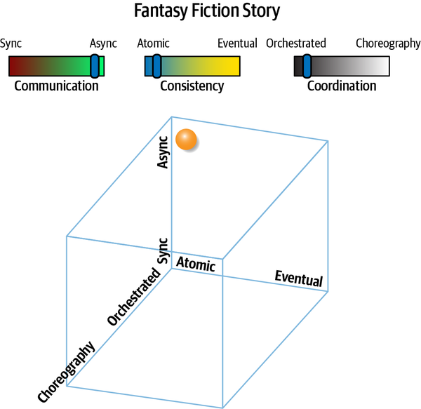
Figure 12-12. Asynchronous communication makes transactionality difficult in this pattern
The structure representation shown in Figure 12-13 starts to show some of the difficulties with this pattern.
Just because a combination of architectural forces exists doesn’t mean it forms an attractive pattern, yet this relatively implausible combination has uses. This pattern resembles the Epic Saga(sao) in all aspects except for communication—this pattern uses asynchronous rather than synchronous communication. Traditionally, one way that architects increase the responsiveness of distributed systems is by using asynchronicity, allowing operations to occur in parallel rather than serially. This may seem like a good way to increase the perceived performance over an Epic Saga(sao).
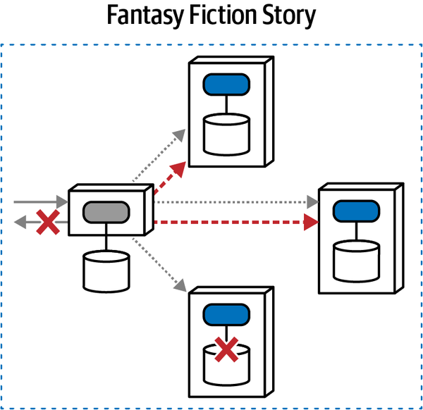
Figure 12-13. The Fantasy Fiction Saga(aao) pattern is far-fetched because transaction coordination for asynchronous communication presents difficulties
However, asynchronicity isn’t a simple change—it adds many
It gets worse. Suppose that workflow Gamma begins, but the first call to the domain service depends on the still pending outcome of Alpha—how can an architect model this behavior? While possible, the complexity grows and grows.
Adding asynchronicity to orchestrated workflows adds asynchronous transactional state to the equation, removing serial assumptions about ordering and adding the possibilities of deadlocks, race conditions, and a host of other parallel system challenges.
This pattern offers the following challenges:
- Coupling level
-
The coupling level is extremely high in this pattern, using an orchestrator and atomicity but with asynchronous communication, which makes coordination more difficult because architects and developers must deal with race conditions and other out-of-order problems imposed by asynchronous communication.
- Complexity level
-
Because the coupling is so difficult, the complexity rises in this pattern as well. There’s not only design complexity, requiring architects to develop overly complex workflows, but also debugging and operational complexity of dealing with asynchronous workflows at scale.
- Responsiveness/availability
-
Because this pattern attempts transactional coordination across calls, responsiveness will be impacted overall and be extremely bad if one or more of the services isn’t available.
- Scale/elasticity
-
High scale is virtually impossible in transaction systems, even with asynchronicity. Scale is much better in the similar pattern Parallel Saga(aeo), which switches atomic to eventual consistency.
| Fantasy Fiction | Ratings |
|---|---|
Communication | Asynchronous |
Consistency | Atomic |
Coordination | Orchestrated |
Coupling | High |
Complexity | High |
Responsiveness/availability | Low |
Scale/elasticity | Low |
This pattern is unfortunately more popular than it should be, mostly from the mis-guided attempt to improve the performance of Epic Saga(sao) while maintaining transactionality; a better option is usually Parallel Saga(aeo).
Horror Story(aac) Pattern
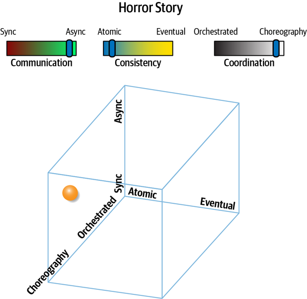
Figure 12-14. The most difficult combination: achieving transactionality while asynchronous and choreographed
Why is this combination so horrible? It combines the most stringent coupling around consistency (atomic) with the two loosest coupling styles, asynchronous and choreography. The structural communication for this pattern appears in Figure 12-15.
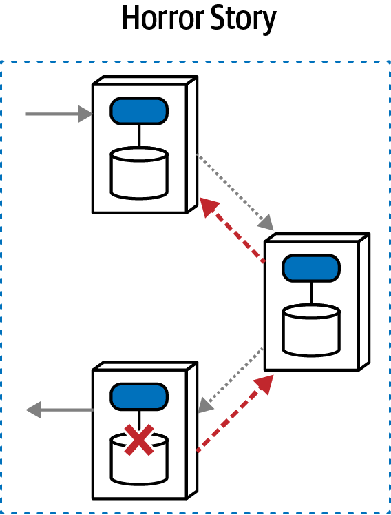
Figure 12-15. This pattern requires a lot of interservice communication because of required transactionality and the lack of a mediator
In this pattern, no mediator exists to manage transactional consistency across multiple services—while using asynchronous communication. Thus, each domain service must track undo information about multiple pending transactions, potentially out of order because of asynchronicity, and coordinate with each other during error conditions. For just one of many possible horrible examples, imagine that transaction Alpha starts and, while pending, transaction Beta starts. One of the calls for the Alpha transaction fails—now, the choreographed services have to reverse the order of firing, undoing each (potentially out-of-order) element of the transaction along the way. The multiplicity and complexity of error conditions makes this a daunting option.
Why might an architect choose this option? Asynchronicity is appealing as a performance boost, yet the architect may still try to maintain transactional integrity, which has many myriad failure modes. Instead, an architect would be better off choosing the Anthology Saga(aec) pattern, which removes holistic transactionality.
The qualitative evaluations for the Horror Story(aac) pattern are as follows:
- Coupling level
-
Surprisingly, the coupling level for this pattern isn’t the worst (that “honor” goes to the Epic Saga(sao) pattern). While this pattern does attempt the worst kind of single coupling (transactionality), it relieves the other two, lacking both a mediator and the coupling—increasing synchronous communication.
- Complexity level
-
Just as the name implies, the complexity of this pattern is truly horrific, the worst of any because it requires the most stringent requirement (transactionality) with the most difficult combination of other factors to achieve that (asynchronicity and choreography).
- Scale/elasticity
-
This pattern does scale better than ones with a mediator, and asynchronicity also adds the ability to perform more work in parallel.
- Responsiveness/availability
-
Responsiveness is low for this pattern, similar to the other patterns that require holistic transactions: coordination for the workflow requires a large amount of interservice “chatter,” hurting performance and responsiveness.
The trade-offs for the Horror Story(aac) pattern appear in Table 12-7.
| Horror Story(aac) | Ratings |
|---|---|
Communication | Asynchronous |
Consistency | Atomic |
Coordination | Choreographed |
Coupling | Medium |
Complexity | Very high |
Responsiveness/availability | Low |
Scale/elasticity | Medium |
The aptly named Horror Story(aac) pattern is often the result of a well-meaning architect starting with an Epic Saga(sao) pattern, noticing slow performance because of complex workflows, and
Parallel Saga(aeo) Pattern
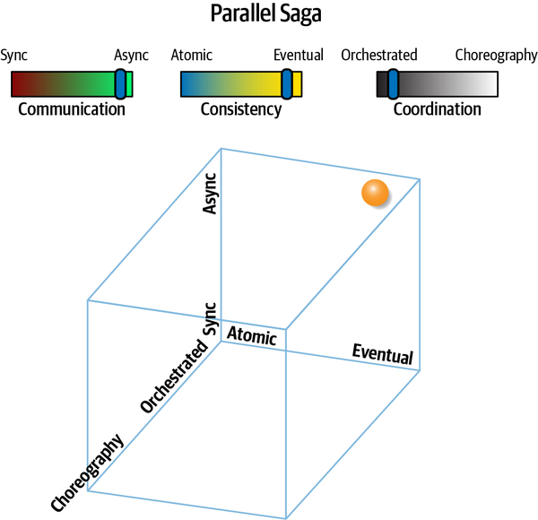
Figure 12-16. Parallel Saga(aeo) offers performance improvements over traditional sagas
The most difficult goals in the Epic Saga(sao) pattern revolve around transactions and synchronous communication, both of which cause bottlenecks and performance degradation. As shown in Figure 12-16, the pattern loosens both restraints.
The isomorphic representation of Parallel Saga(aeo) appears in Figure 12-17.
This pattern uses a mediator, making it suitable for complex workflows. However, it uses asynchronous communication, allowing for better responsiveness and parallel execution. Consistency in the pattern lies with the domain services, which may require some synchronization of shared data, either in the background or driven via the mediator. As in other architectural problems that require coordination, a mediator becomes quite useful.
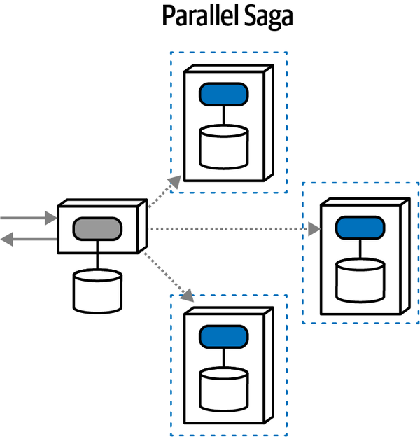
Figure 12-17. Each service owns its own transactionality; the mediator coordinates request and response
For example, if an error occurs during the execution of a workflow, the mediator can send asynchronous messages to each involved domain service to compensate for the failed change, which may entail retries, data synchronization, or a host of other remediations.
Of course, the loosening of constraints implies that some benefits will be traded off, which is the nature of software architecture. Lack of transactionality imposes more burden on the mediator to resolve error and other workflow issues. Asynchronous communication, while offering better responsiveness, makes resolving timing and synchronization issues difficult—race conditions, deadlocks, queue reliability, and a host of other distributed architecture headaches reside in this space.
The Parallel Saga(aeo) pattern exhibits the following qualitative scores:
- Coupling level
-
This pattern has a low coupling level, isolating the coupling-intensifying force of transactions to the scope of the individual domain services. It also utilizes asynchronous communication, further decoupling services from wait states, allowing for more parallel processing but adding a time element to an architect’s coupling analysis.
- Complexity level
-
The complexity of the Parallel Saga(aeo) is also low, reflecting the lessening of coupling stated previously. This pattern is fairly easy for architects to understand, and orchestration allows for simpler workflow and error-handling designs.
- Scale/elasticity
-
Using asynchronous communication and smaller transaction boundaries allows this architecture to scale quite nicely, and with good levels of isolation between services. For example, in a microservices architecture, some public-facing services might need higher levels of scale and elasticity, where back office services don’t need scale but higher levels of security. Isolating transactions at the domain level frees the architecture to scale around domain concepts.
- Responsiveness/availability
-
Because of lack of coordinated transactions and asynchronous communication, the responsiveness of this architecture is high. In fact, because each of these services maintains its own transactional context, this architecture is well suited to highly variable service performance footprints between services, allowing architects to scale some services more than others because of demand.
The ratings associated with the Parallel Saga(aeo) pattern appear in Table 12-8.
| Parallel Saga(aeo) | Ratings |
|---|---|
Communication | Asynchronous |
Consistency | Eventual |
Coordination | Orchestrated |
Coupling | Low |
Complexity | Low |
Responsiveness/availability | High |
Scale/elasticity | High |
Overall, the Parallel Saga(aeo) pattern offers an attractive set of trade-offs for many scenarios, especially with complex workflows that need high scale.
Anthology Saga(aec) Pattern
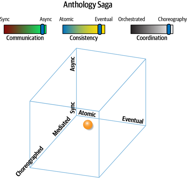
Figure 12-18. The Anthology Saga(aec) pattern offers the opposite extremes of the Epic Saga, and is therefore the least coupled pattern
The anthology pattern uses message queues to send asynchronous messages to other domain services without orchestration, as illustrated in Figure 12-19.
As you can see, each service maintains its own transactional integrity, and no orchestrator exists, forcing each domain service to include more context about the workflows they participate in, including error handling and other coordination strategies.
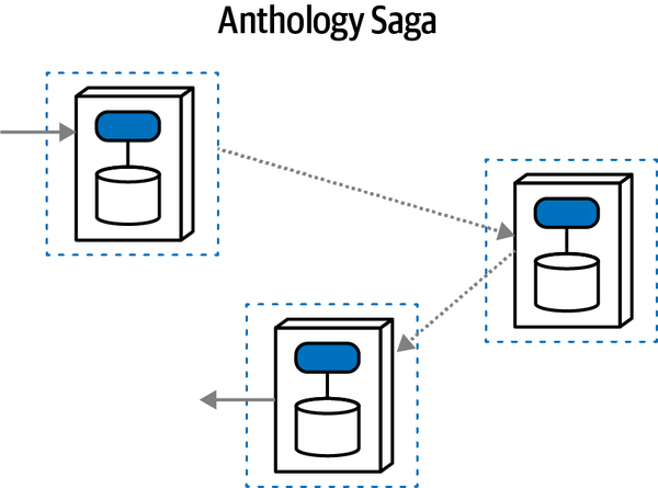
Figure 12-19. Lack of orchestration, eventual consistency, and asynchronicity make this pattern highly decoupled but a challenge for coordination
The lack of orchestration makes services more complex but allows for much higher throughput, scalability, elasticity, and other beneficial operational architecture characteristics. No bottlenecks or coupling choke points exist in this architecture, allowing for high responsiveness and scalability.
However, this pattern doesn’t work particularly well for complex workflows, especially around resolving data consistency errors. While it may not seem possible without an orchestrator, stamp coupling (“Stamp Coupling for Workflow Management”) may be used to carry workflow state, as described in the similar Phone Tag Saga(sac) pattern.
This pattern works best for simple, mostly linear workflows, where architects desire high processing throughput. This pattern provides the most potential for both high performance and scale, making it an attractive choice when those are key drivers for the system. However, the degree of decoupling makes coordination difficult, prohibitively so for complex or critical workflows.
The short-story-inspired Anthology Saga(aec) pattern has the following characteristics:
- Coupling level
-
Coupling for this pattern is the lowest for any other combination of forces, creating a highly decoupled architecture well suited for high scale and elasticity.
- Complexity level
-
While the coupling is extremely low, complexity is correspondingly high, especially for complex workflows where an orchestrator (lacking here) is convenient.
- Scale/elasticity
-
This pattern scores the highest in the scale and elasticity category, correlating with the overall lack of coupling found in this pattern.
- Responsiveness
-
Responsiveness is high in this architecture because of a lack of speed governors (transactional consistency, synchronous communication) and use of responsiveness accelerators (choreographed coordination).
The ratings table for the Anthology Saga(aec) pattern appear in Table 12-9.
| Anthology Saga(aec) | Ratings |
|---|---|
Communication | Asynchronous |
Consistency | Eventual |
Coordination | Choreographed |
Coupling | Very low |
Complexity | High |
Responsiveness/availability | High |
Scale/elasticity | Very high |
The Anthology Saga(aec) pattern is well suited to extremely high throughput communication with simple or infrequent error conditions.
Architects can implement the patterns described in this section in a variety of ways. For example, architects can manage transactional sagas through atomic transactions by using compensating updates or by managing transactional state with eventual consistency. This section showed the advantages and disadvantages of each approach, which will help an architect decide which transactional saga pattern to use.
State Management and Eventual Consistency
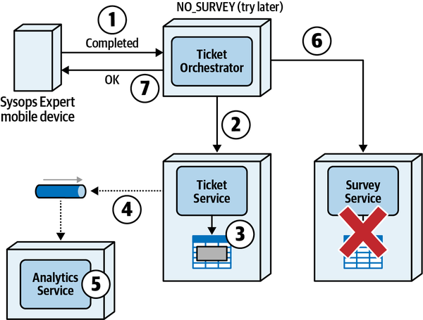
Figure 12-20. The Fairy Tale Saga leads to better responsiveness, but leaves data sources out of sync with one another until they can be corrected
Notice that the Survey Service is not available during the scope of the distributed transaction. However, with this type of saga, rather than issue a compensating update, the state of the saga is changed to NO_SURVEY and a successful response is sent to the Sysops Expert (step 7 in the diagram). The Ticket Orchestrator Service then works asynchronously (behind the scenes) to resolve the error programmatically by retries and error analysis. If it cannot resolve the error, the Ticket Orchestrator Service sends the error to an administrator or supervisor for manual repair and processing.
By managing the state of the saga rather than issuing compensating updates,
Saga State Machines
To illustrate how a saga state machine works, consider the following workflow of a new problem ticket created by a customer in the Sysops Squad system:
-
The customer enters a new problem ticket into the system.
-
The ticket is assigned to the next available Sysops Squad expert.
-
The ticket is then routed to the expert’s mobile device.
-
The expert receives the ticket and works on the issue.
-
The expert finishes the repair and marks the ticket as complete.
-
A survey is sent to the customer.
START node indicating the saga entry point, and terminates with the CLOSED node indicating the saga exit point. 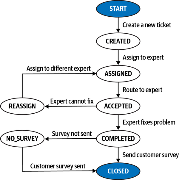
Figure 12-21. State diagram for creating a new problem ticket
The following items describe in more detail this transactional saga and the corresponding states and transition actions that happen within each state:
- START
-
The transactional saga starts with a customer entering a new problem ticket into the system. The customer’s support plan is verified, and the ticket data is validated. Once the ticket is inserted into the ticket table in the database, the transactional saga state moves to CREATED and the customer is notified that the ticket has been successfully created. This is the only possible outcome for this state transition—any errors within this state prevent the saga from starting.
- CREATED
-
Once the ticket is successfully created, it is assigned to a Sysops Squad expert. If no expert is available to service the ticket, it is held in a wait state until an expert is available. Once an expert is assigned, the saga state moves to the ASSIGNED state. This is the only outcome for this state transition, meaning the ticket is held in CREATED state until it can be assigned.
- ASSIGNED
-
Once a ticket is assigned to an expert, the only possible outcome is to route the ticket to the expert. It is assumed that during the assignment algorithm, the expert has been located and is available. If the ticket cannot be routed because the expert cannot be located or is unavailable, the saga stays in this state until it can be routed. Once routed, the expert must acknowledge that the ticket has been received. Once this happens, the transactional saga state moves to ACCEPTED. This is the only possible outcome for this state transition.
- ACCEPTED
-
There are two possible states once a ticket has been accepted by a Sysops Squad expert: COMPLETED or REASSIGN. Once the expert finishes the repair and marks the ticket as “complete,” the state of the saga moves to COMPLETED. However, if for some reason the ticket was wrongly assigned or the expert is not able to finish the repair, the expert notifies the system and the state moves to REASSIGN.
- REASSIGN
-
Once in this saga state, the system will reassign the ticket to a different expert. Like the CREATED state, if an expert is not available, the transactional saga will remain in the REASSIGN state until an expert is assigned. Once a different expert is found and the ticket is once again assigned, the state moves into the ASSIGNED state, waiting to be accepted by the other expert. This is the only possible outcome for this state transition, and the saga remains in this state until an expert is assigned to the ticket.
- COMPLETED
-
The two possible states once an expert completes a ticket are CLOSED or NO_SURVEY. When the ticket is in this state, a survey is sent to the customer to rate the expert and the service, and the saga state is moved to CLOSED, thus ending the transaction saga. However, if the Survey Service is unavailable or an error occurs while sending the survey, the state moves to NO_SURVEY, indicating that the issue was fixed but no survey was sent to the customer.
- NO_SURVEY
-
In this error condition state, the system continues to try sending the survey to the customer. Once successfully sent, the state moves to CLOSED, marking the end of the transactional saga. This is the only possible outcome of this state transaction.
In many cases, it’s useful to put the list of all possible state transitions and the corresponding transition action in some sort of table. Developers can then use this table to implement the state transition triggers and possible error conditions in an orchestration service (or respective services if using choreography). An example of this practice is shown in Table 12-10, which lists all the possible states and actions that are triggered when the state transition occurs.
| Initiating state | Transition state | Transaction action |
|---|---|---|
START | CREATED | Assign ticket to expert |
CREATED | ASSIGNED | Route ticket to assigned expert |
ASSIGNED | ACCEPTED | Expert fixes problem |
ACCEPTED | COMPLETED | Send customer survey |
ACCEPTED | REASSIGN | Reassign to a different expert |
REASSIGN | ASSIGNED | Route ticket to assigned expert |
COMPLETED | CLOSED | Ticket saga done |
COMPLETED | NO_SURVEY | Send customer survey |
NO_SURVEY | CLOSED | Ticket saga done |
The choice between using compensating updates or state management
Techniques for Managing Sagas
NEW_TICKET, CANCEL_TICKET, and so on) are contained within the Transaction enum, providing a single place within the source code for listing and documenting the various sagas that exist within an application context. Example 12-1. Source code defining a transactional saga annotation (Java)
@Retention(RetentionPolicy.RUNTIME)@Target(ElementType.TYPE)public@interfaceSaga{publicTransaction[]value();publicenumTransaction{NEW_TICKET,CANCEL_TICKET,NEW_CUSTOMER,UNSUBSCRIBE,NEW_SUPPORT_CONTRACT}}
Example 12-2. Source code defining a transactional saga attribute (C#)
[AttributeUsage(AttributeTargets.Class)]classSaga:System.Attribute{publicTransaction[]transaction;publicenumTransaction{NEW_TICKET,CANCEL_TICKET,NEW_CUSTOMER,UNSUBSCRIBE,NEW_SUPPORT_CONTRACT};}
Once defined, these annotations or attributes can be used to identify
SurveyServiceAPI class as the service entry point) is involved in the NEW_TICKET saga, whereas the Ticket Service (identified by the TicketServiceAPI class as the service entry point) is involved in two sagas: the NEW_TICKET and the CANCEL_TICKET. Example 12-3. Source code showing the use of the transactional saga annotation (Java)
@ServiceEntrypoint@Saga(Transaction.NEW_TICKET)publicclassSurveyServiceAPI{...}@ServiceEntrypoint@Saga({Transaction.NEW_TICKET,)Transaction.CANCEL_TICKET})publicclassTicketServiceAPI{...}
Notice how the NEW_TICKET saga includes the Survey Service and the Ticket Service. This is valuable information to a developer because it helps them define the testing scope when making changes to a particular workflow or saga, and also lets them know what other services might be impacted by a change to one of the services within the transactional saga.
Using these annotations and custom attributes, architects and developers can write simple command-line interface (CLI) tools to walk through a codebase or source code repository to provide saga information in real time. For example, using a simple custom code-walk tool, a developer, architect, or even a business analyst can query what services are involved for the NEW_TICKET saga:
$./sagatool.sh NEW_TICKET -services -> Ticket Service -> Assignment Service -> Routing Service -> Survey Service$
A custom code-walking tool can look at each class file in the application context containing the @ServiceEntrypoint custom annotation (or attribute) and check the @Saga custom annotation for the presence of the particular saga (in this case, Transaction.NEW_TICKET). This sort of custom tool is not complicated to write, and can help provide valuable information when managing transactional sagas.
Sysops Squad Saga: Atomic Transactions and Compensating Updates
Tuesday, April 5, 09:44
Addison and Austen met first thing with Logan to hash out the issues around transactionality in the new microservices architecture in the longish conference room.
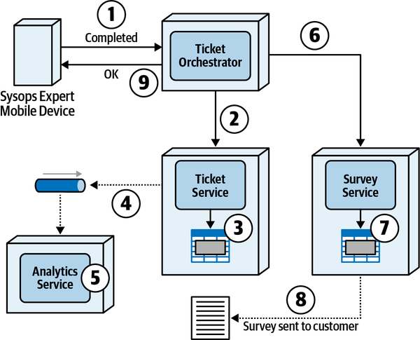
Figure 12-22. The epic saga requires the ticket status to be updated and survey to be sent in one synchronous atomic operation
Logan continued, “I’ve also created a list that describes each step. The circled numbers on the diagram match up with the workflow.”
-
The Sysops Squad expert marks the ticket as complete using an app on their mobile device, which is synchronously received by the Ticket Orchestrator Service.
-
The Ticket Orchestrator Service sends a synchronous request to the Ticket Service to change the state of the ticket from “in-progress” to “complete.”
-
The Ticket Service updates the ticket number to “complete” in the database table and commits the update.
-
As part of the ticket completion process, the Ticket Service asynchronously sends ticketing information (such as ticket repair time, ticket wait time, duration, and so on) to a queue to be picked up by the Analytics Service. Once sent, the Ticket Service sends an acknowledgment to the Ticket Orchestrator Service that the update is complete.
-
At about the same time, the Analytics Service asynchronously receives the updated ticket analytics and starts to process the ticket information.
-
The Ticket Orchestrator Service then sends a synchronous request to the Survey Service to prepare and send the customer survey to the customer.
-
The Survey Service inserts data into a table with the survey information (customer, ticket info, and timestamp) and commits the insert.
-
The Survey Service then sends the survey to the customer via email and returns an acknowledgment back to the Ticket Orchestrator Service that the survey processing is complete.
-
Finally, the Ticket Orchestrator Service sends a response back to the Sysops Squad expert’s mobile device stating that the ticket completion processing is done. Once this happens, the expert can select the next problem ticket assigned to them.
“Wow, this is really helpful. How long did it take you to create this?” said Addison.
“Not a little time, but it’s come in handy. You aren’t the only group that’s confused about how to get all these moving pieces to work together. This is the hard part of software architecture. Everyone understand the basics of the workflow?”
To a sea of nods, Logan continued, “One of the first issues that occurs with compensating updates is that since there’s no transactional isolation within a distributed transaction (see “Distributed Transactions”), other services may have taken action on the data updated within the scope of the distributed transaction before the distributed transaction is complete. To illustrate this issue, consider the same Epic Saga example appearing in Figure 12-23: the Sysops Squad expert marks a ticket as complete, but this time the Survey Service is not available. In this case, a compensating update (step 7 in the diagram) is sent to the Ticket Service to reverse the update, changing the ticket state from completed back to in-progress (step 8 in the diagram).”
“Notice also in Figure 12-23 that since this is an atomic distributed transaction, an error is then sent back to the Sysops Squad expert indicating that the action was not successful and to try again. Now, a question for you: why should the Sysops Squad expert have to worry that the survey is not sent?”
Austen pondered a moment. “But wasn’t that part of the workflow in the monolith? All that stuff happened within a transaction, if I remember correctly.”
“Yeah, but I always thought that was weird, just never said anything,” said Addison. “I don’t see why the expert should worry about the survey. The expert just wants to get on to the next ticket assigned to them.”
“Right,” Logan said. “This is the issue with atomic distributed transactions—the end user is unnecessarily semantically coupled to the business process. But notice that Figure 12-23 also illustrates the issue with the lack of transaction isolation within a distributed transaction. Notice that as part of the original update to mark the ticket as complete, the Ticket Service asynchronously sent the ticket information to a queue (step 4 in the diagram) to be processed by the Analytics Service (step 5). However, when the compensating update is issued to the Ticket Service (step 7), the ticket information has already been processed by the Analytics Service in step 5.”
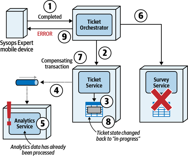
Figure 12-23. Epic Saga(sao) requires compensation, but side effects can occur
“We call this a side effect within distributed architectures.
Logan paused for a moment, then continued, “Another issue—”
Austen interrupted, “Another issue?”
Logan smiled. “Another issue regarding compensating updates is compensation failures. Keeping with the same Epic Saga example for completing a ticket, notice in Figure 12-24 that in step 7 a compensating update is issued to the Ticket Service to change the state from completed back to in-progress. However, in this case, the Ticket Service generates an error when trying to change the state of the ticket (step 8).”
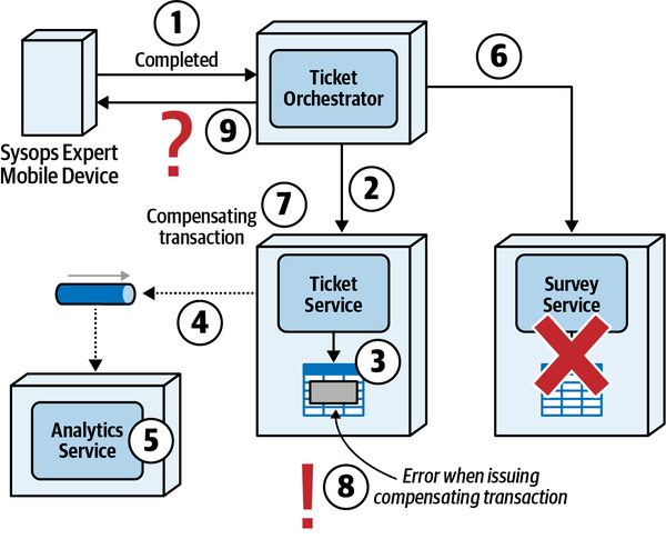
Figure 12-24. Compensating updates within an Epic Saga can fail, leading to inconsistency and confusion about what action to take in the event of a compensation failure
“I’ve seen that happen! It took forever to track that down,” said Addison.
“Architects and developers tend to assume that compensating updates will always work,” Logan said. “But sometimes they don’t. In this case, as shown in Figure 12-24, there is confusion about what sort of response to send back to the end user (in this case, the Sysops Squad expert). The ticket status is already marked as complete because the compensation failed, so attempting the “mark as complete” request again might only lead to yet another error (such as Ticket already marked as complete). Talk about confusion on the part of the end user!”
“Yeah, I can imagine the developers coming to us to ask us how to resolve this issue,” Addison said.
“Often developers are good checks on incomplete or confusing architecture solutions. If they are confused, there may be a good reason,” said Logan. “OK, one more issue. Atomic distributed transactions and corresponding compensating updates also impact responsiveness. If an error occurs, the end user must wait until all corrective action is taken (through compensating updates) before a response is sent telling the user about the error.”
“Isn’t that where the change to eventual consistency helps, for responsiveness?” asked Austen.
“Yes, while responsiveness can sometimes be resolved by asynchronously issuing compensating updates through eventual consistency (such as with the Parallel Saga and the Anthology Saga pattern), nevertheless most atomic distributed transactions have worse responsiveness when compensating updates are involved.”
“OK, that makes sense—atomic coordination will always have overhead,” Austen said.
“That’s a lot of information. Let’s build a table to summarize some of the trade-offs associated with atomic distributed transactions and compensating updates.” (See Table 12-12.)
Logan said, “While this compensating transaction pattern exists, it also offers a number of challenges. Who wants to name one?”
“I know: a service cannot perform a rollback,” said Austen. “What if one of the services cannot successfully undo the previous operation? The orchestrator must have coordination code to indicate that the transaction wasn’t successful.”
“Right—what about another?”
"To lock or not lock participating services?" said Addison. “When the mediator places a call to a service and it updates a value, the mediator will make calls to subsequent services that are part of the workflow. However, what happens if another request appears for the first service contingent on the outcome of the first request’s resolution, either from the same mediator or a different context? This distributed architecture problem becomes worse when the calls are asynchronous rather than synchronous (illustrated in “Phone Tag Saga(sac) Pattern”). Alternatively, the mediator could insist that other services don’t accept calls during the course of a workflow, which guarantees a valid transaction but destroys performance and scalability.”
Logan said, “Correct. Let’s get philosophical for a moment. Conceptually, transactions force participants to stop their individual worlds and synchronize on a particular value. This is so easy to model with monolithic architectures and relational databases that architects overuse transactions in those systems. Much of the real world isn’t transactional,
“Is there an alternative to using an Epic Saga?” Addison asked.
“Yes!” Logan said. “A more realistic approach to the scenario described in Figure 12-24 might be to use either a Fairy Tale Saga or a Parallel Saga pattern. These sagas rely on asynchronous eventual consistency and state management rather than atomic distributed transactions with compensating updates when errors occur. With these types of sagas, the user is less impacted by errors that might occur within the distributed transaction, because the error is addressed behind the scenes, without end-user involvement. Responsiveness is also better with the state management and eventual consistency approach, because the user does not have to wait for corrective action to be taken within the distributed transaction. If we have issues with atomicity, we can investigate those patterns as alternatives.”
“Thanks—that’s a lot of material, but now I see why the architects made some of the decisions in the new architecture,” Addison said.
Chapter 13. Contracts
Friday, April 15, 12:01
Addison met with Sydney over lunch in the cafeteria to chat about coordination
“Why not just use gRPC for all the communication? I heard it’s really fast,” said Sydney.
“Well, that’s an implementation, not an architecture,” Addison said. “We need to decide what types of contracts we want before we choose how to implement them. First, we need to decide between tight or loose contracts. Once we decide on the type, I’ll leave it to you to decide how to implement them, as long as they pass our fitness functions.”
“What determines what kind of contract we need?” Sydney said.
However much an architecture can discern a relationship like this one, some forces cut across the conceptual space and affect all of the other dimensions equally. If pursuing the visual three-dimensional metaphor, these cross-cutting forces act as an additional dimension, much as time is orthogonal to the three physical dimensions.
Figure 13-1. Three-dimensional intersecting space for messaging forces in distributed architectures
One constant factor in software architecture that cuts across and affects virtually every aspect of architect decision making is contracts, broadly defined as how disparate parts of an architecture connect with one another. The dictionary definition of a contract is as follows:
- contract
-
A written or spoken agreement, especially one concerning employment, sales, or tenancy, that is intended to be enforceable by law.
In software, we use contracts broadly to describe things like integration points in architecture, and many contract formats are part of the design process of software development: SOAP, REST, gRPC, XMLRPC, and an alphabet soup of other acronyms. However, we broaden that definition and make it more consistent:
- hard parts contract
-
The format used by parts of an architecture to convey information or dependencies.
This definition of contract encompasses all techniques used to “wire together” parts of a system, including transitive dependencies for frameworks and libraries, internal and external integration points, caches, and any other communication among parts.
This chapter illustrates the effects of contracts on many parts of architecture, including static and dynamic quantum coupling, as well as ways to improve (or harm) the effectiveness of workflows.
Strict Versus Loose Contracts
Like many things in software architecture, contracts don’t exist
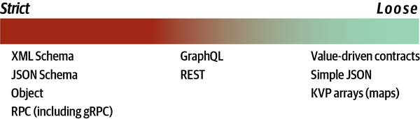
Figure 13-2. The spectrum of contract types, from strict to loose
A strict contract requires adherence to names, types, ordering, and all other details, leaving no ambiguity. An example of the strictest possible contract in software is a remote method call, using a platform mechanism such as RMI in Java. In that case, the remote call mimics an internal method call, matching name, parameters, types, and all other details.
Many strict contract formats mimic the semantics of method calls.
Many architects like strict contracts because they model the identical semantic behavior of internal method calls.
Even an ostensibly loose format such as
Example 13-1. Strict JSON contract
{"$schema":"http://json-schema.org/draft-04/schema#","properties":{"acct":{"type":"number"},"cusip":{"type":"string"},"shares":{"type":“number", "minimum": 100}},"required": ["acct", "cusip", "shares"]}
The first line references the schema definition we use and will validate against. We define three properties (acct, cusip, and shares), along with their types and, on the last line, which ones are required. This creates a strict contract, with required fields and types specified.
Examples of looser contracts include formats such
Similarly, GraphQL is used by distributed architectures to provide
Example 13-2. Customer Wishlist Profile representation
typeProfile{name:String}
Example 13-3. Customer Profile representation
typeProfile{name:Stringaddr1:Stringaddr2:Stringcountry:String...}
The concept of profile appears in both examples but with different values. In this scenario, the Customer Wishlist doesn’t have internal access to the customer’s name, only a unique identifier. Thus, it needs access to a Customer Profile that maps the identifier to the customer name. The Customer Profile, on the other hand, includes a large amount of information about the customer in addition to the name. As far as Wishlist is concerned, the only interesting thing in Profile is the name.
A common anti-pattern that some architects fall victim to is to assume that Wishlist might eventually need all the other parts, so the architects include them in the contract from the outset. This is an example of stamp coupling and an anti-pattern in most cases, because it introduces breaking changes where they aren’t needed, making the architecture fragile yet providing little benefit. For example, if the Wishlist cares about only the customer name from Profile, but the contract specifies every field in Profile (just in case), then a change in Profile that Wishlist doesn’t care about causes a contract breakage and coordination to fix. Keeping contracts at a “need to know” level strikes a balance between semantic coupling and necessary information without creating needless fragility in integration architecture.
At the far end of the spectrum of contract coupling lie extremely loose contracts, often expressed as name-value pairs in formats like YAML or JSON, as illustrated in Example 13-4.
Example 13-4. Name-value pairs in JSON
{"name":"Mark","status":"active","joined":"2003"}
Nothing but the raw facts in this example! No additional metadata, type information, or anything else, just name-value pairs.
Using such loose contracts allows for extremely decoupled
Trade-Offs Between Strict and Loose Contracts
When should an architect use strict contracts and when should they use looser ones? Like all the hard parts of architecture, no generic answer exists for this question, so it is important for architects to understand when each is most suitable.
Strict contracts
Stricter contracts have a number of advantages, including these:
- Guaranteed contact fidelity
-
Building schema verification within contracts ensures exact adherence to the values, types, and other governed metadata. Some problem spaces benefit from tight coupling for contract changes.
- Versioned
- Strict contracts generally require a versioning strategy to supporttwo endpoints that accept different values or to manage domain evolution over time. This allows gradual changes to integration points while supporting a selective number of past versions to make integration collaboration easier.
- Easier to verify at build time
-
Many schema tools provide mechanisms to verify contracts at build time, adding a level of type checking for integration points.
- Better documentation
-
Distinct parameters and types provide excellent documentation with no ambiguity.
Strict contracts also have a few disadvantages:
- Tight coupling
- By our general definition of coupling, strict contracts create tightcoupling points. If two services share a strict contract and the contract changes, both services must change.
- Versioned
-
This appears in both advantages and disadvantages. While keeping distinct versions allows for precision, it can become an integration nightmare if the team doesn’t have a clear deprecation strategy or tries to support too many versions.
Loose contracts
Loose contracts, such as name-value pairs, offer the least
These are some advantages of loose contracts:
- Highly decoupled
-
Many architects have a stated goal for microservices architectures
that includes high levels of decoupling, and loose contracts provide the most flexibility. - Easier to evolve
-
Because little or no schema information exists, these contracts can evolve more freely. Of course, semantic coupling changes still require coordination across all interested parties—implementation cannot reduce semantic coupling—but loose contracts allow easier implementation evolution.
Loose contracts also have a few disadvantages:
- Contract management
-
Loose contracts by definition don’t have strict contract features, which may cause problems such as misspelled names, missing name-value pairs, and other deficiencies that schemas would fix.
- Requires fitness functions
- To solve the contract issues just described, many teams useconsumer-driven contracts as an architecture fitness function to make sure that loose contracts still contain sufficient information for the contract to function.
For an example of the common trade-offs encountered by architects, consider the example of contracts in microservice architectures.
Contracts in Microservices
Coupling levels
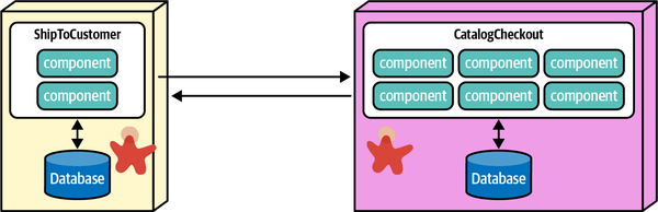
Figure 13-3. Two services that must share domain information about the customer
The architect could implement both services in the same technology stack and use a strictly typed contract, either a platform-specific remote procedure protocol (such as RMI) or an implementation-independent one like gRPC, and pass the customer information from one to another with high confidence of contract fidelity. However, this tight coupling violates one of the aspirational goals of microservices architectures, where architects try to create decoupled services.
Consider the alternative approach, where each service has its own internal representation of Customer, and the integration uses name-value pairs to pass information from one service to another, as illustrated in Figure 13-4.
Here, each service has its own bounded-context definition of Customer. When passing information, the architect utilizes name-value pairs in JSON to pass the relevant information in a loose contract.
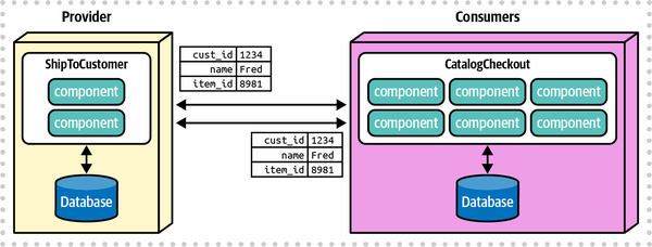
Figure 13-4. Microservices with their own internal semantic representation can pass values in simple messages
This loose coupling satisfies many of the overarching goals of microservices. First, it creates highly decoupled services modeled after bounded contexts, allowing each team to evolve internal representations as aggressively as needed. Second, it creates implementation decoupling. If both services start in the same technology stack, but the team in the second decides to move to another platform, it likely won’t affect the first service at all. All platforms in common use can produce and consume name-value pairs, making them the lingua franca of integration architecture.
The biggest downside of loose contracts is contract fidelity—as an
Consumer-driven contracts
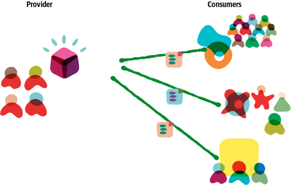
Figure 13-5. Consumer-driven contracts allow the provider and consumers to stay in sync via automated architectural governance
In this example, the team on the left provides bits of (likely) overlapping information to each of the consumer teams on the right. Each consumer creates a contract specifying required information and passes it to the provider, who includes their tests as part of a continuous integration or deployment pipeline. This allows each team to specify the contract as strictly or loosely as needed while guaranteeing contract fidelity as part of the build process. Many consumer-driven contract testing tools provide facilities to automate build-time checks of contracts, providing another layer of benefit similar to stricter contracts.
Consumer-driven contracts are quite common in microservices architecture because they allow architects to solve the dual problems of loose coupling and governed integration. Trade-offs of consumer-driven contracts are shown in Table 13-3.
Advantages of consumer-driven contracts are as follows:
- Allow loose contract coupling between services
-
Using name-value pairs is the loosest possible coupling between two services, allowing implementation changes with the least chance of breakage.
- Allow variability in strictness
-
If teams use architecture fitness functions, architects can build stricter verifications than typically offered by schemas or other type-additive tools. For example, most schemas allow architects to specify things like numeric type but not acceptable ranges of values. Building fitness functions allows architects to build as much specificity as they like.
- Evolvable
-
Loose coupling implies evolvability. Using simple name-value pairs allows integration points to change implementation details without breaking the semantics of the information passed between services.
These are disadvantages of consumer-driven contracts:
- Require engineering maturity
-
Architecture fitness functions are a great example of a capability that really works well only when well-disciplined teams have good practices and don’t skip steps. For example, if all teams run continuous integration that includes contract tests, then fitness functions provide a good verification mechanism. On the other hand, if many teams ignore failed tests or are not timely in running contract tests, integration points may be broken in architecture longer than desired.
- Two interlocking mechanisms rather than one
-
Architects often look for a single mechanism to solve problems, and many of the schema tools have elaborate capabilities to create end-to-end connectivity. However, sometimes two simple interlocking mechanisms can solve the problem more simply. Thus, many architects use the combination of name-value pairs and consumer-driven contracts to validate contracts. However, this means that teams require two mechanisms rather than one.
The architect’s best solution for this trade-off comes down to team maturity and decoupling with loose contracts versus complexity plus certainty with stricter contracts.
Stamp Coupling
A common pattern and sometimes anti-pattern in distributed
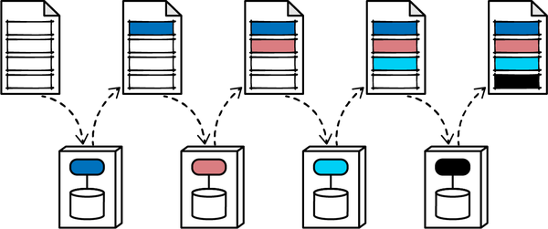
Figure 13-6. Stamp coupling between four services
Each service accesses (either reads, writes, or both) only a small portion of the data structure passed between each service. This pattern is common when an industry-standard document format exists, typically in XML. For example, the travel industry has a global standard XML document format that specifies details about travel itineraries. Several systems that work with travel-related services pass the entire document around, updating only their relevant sections.
Stamp coupling, however, is often an accidental anti-pattern, where an architect has over-specified the details in a contract that aren’t needed or accidentally consumes far too much bandwidth for mundane calls.
Over-Coupling via Stamp Coupling
Going back to our Wishlist and Profile Services, consider
In this example, even though the Wishlist Service needs only the name (accessed via a unique ID), the architect has coupled Profile’s entire data structure as the contract, perhaps in a misguided effort for future proofing. However, the negative side effect of too much coupling in contracts is brittleness. If Profile changes a field that Wishlist doesn’t care about, such as state, it still breaks the contract.
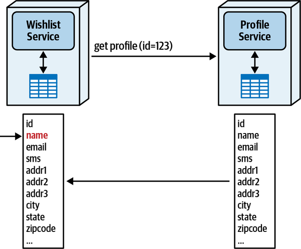
Figure 13-7. The Wishlist Service is stamp coupled to the Profile Service
Over-specifying details in contracts is generally an anti-pattern but easy to fall into when also using stamp coupling for legitimate concerns, including uses such as workflow management (see “Stamp Coupling for Workflow Management”).
Bandwidth
The other inadvertent anti-pattern that some architects fall into
Consider the previous example for 2,000 requests per second. If each payload is 500 KB, then the bandwidth required for this single request equals 1,000,000 KB per second! This is obviously an egregious use of bandwidth for no good reason. Alternatively, if the coupling between Wishlist and Profile contained only the necessary information, name, the overhead changes to 200 bytes per second, for a perfectly reasonable 400 KB.
Stamp coupling can create problems when overused, including issues caused by coupling too tightly to bandwidth. However, like all things in architecture, it has beneficial uses as well.
Stamp Coupling for Workflow Management
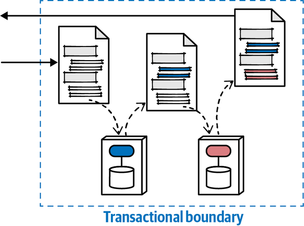
Figure 13-8. Using stamp coupling for workflow management
In this example, an architect designs the contract to include workflow information: status of the workflow, transactional state, and so on. As each domain service accepts the contract, it updates its portion of the contract and state for the workflow, then passes it along. At the end of the workflow, the receiver can query the contract to determine success or failure, along with status and information such as error messages. If the system needs to implement transactional consistency throughout, then domain services should rebroadcast the contract to previously visited services to restore atomic consistency.
Using stamp coupling to manage workflow does create higher
Sysops Squad Saga: Managing Ticketing Contracts
Tuesday, May 10, 10:10
Sydney and Addison met again in the cafeteria over coffee to discuss the contracts in the ticket management workflow.
“The contracts between the orchestrator and the two ticket services, Ticket Management and Ticket Assignment, are tight; that information is highly semantically coupled and likely to change together,” Addison said. “For example, if we add new types of things to manage, the assignment must sync up. The Notification and Survey Service can be much looser—the information changes more slowly, and doesn’t benefit from brittle coupling.”
Sydney said, “All those decisions make sense—but what about the contract between the orchestrator and the Sysops Squad expert application? It seems that would need as tight a contract as assignment.”
“Good catch—nominally, we would like the contract with the mobile application to match ticket assignment. However, we deploy the mobile application through a public app store, and their approval process sometimes takes a long time. If we keep the contracts looser, we gain flexibility and slower rate of change.”
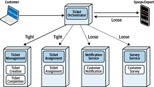
Figure 13-9. Types of contracts between collaborators in the ticket management workflow
They both wrote an ADR for this:
ADR: Loose Contract for Sysops Squad Expert Mobile Application
Context
The mobile application used by Sysops Squad experts must be deployed through the public app store, imposing delays on the ability to update contracts.Decision
We will use a loose, name-value pair contract to pass information to and from the orchestrator and the mobile application.We will build an extension mechanism to allow temporary extensions for short-term flexibility.
Consequences
The decision should be revisited if the app store policy allows for faster (or continuous) deployment.More logic to validate contracts must reside in the orchestrator and mobile application.
Chapter 14. Managing Analytical Data
Tuesday, May 31, 13:23
Logan and Dana (the data architect) were standing outside the big conference room, chatting after the weekly status meeting.
“How are we going to handle analytical data in this new architecture?” asked Dana. “We’re splitting the databases into small parts, but we’re going to have to glue all that data back together for reporting and analytics. One of the improvements we’re trying to implement is better predictive planning, which means we are using more data science and statistics to make more strategic decisions. We now have a team that thinks about analytical data, and we need a part of the system to handle this need. Are we going to have a data warehouse?”
Logan said, “We looked into creating a data warehouse, and while it solved the consolidation problem, it had a bunch of issues for us.”
Previous Approaches
The split between operational and analytical data is hardly a new problem—the fundamental different uses of data have existed as long as data. As architecture styles have emerged and evolved, approaches for how to handle data have changed and evolved similarly.
The Data Warehouse
Back in earlier eras of software development (for example,
Architects made an early attempt to provide queriable analytical data with the Data Warehouse pattern. The basic problem they tried to address goes to the core of the separation of operational and analytical data: the formats and schemas of one don’t necessarily fit (or even allow the use of) the other. For example, many analytical problems require aggregations and calculations, which are expensive operations on relational databases, especially those already operating under heavy transactional load.
The Data Warehouse patterns that evolved had slight variations, mostly based on vendor offerings and capabilities. However, the pattern had many common characteristics. The basic assumption was that operational data was stored in relational databases directly accessible via the network. Here are the main characteristics of the Data Warehouse pattern:
- Data extracted from many sources
-
As the operational data resided in individual databases, part of this pattern specified a mechanism for extracting the data into another (massive) data store, the “warehouse” part of the pattern. It wasn’t practical to query across all the various databases in the organization to build reports, so the data was extracted into the warehouse solely for analytical purposes.
- Transformed to single schema
- Often, operational schemas don’t match the ones needed for reporting. For example, an operational system needs to structure schemas and behavior around transactions, whereas an analytical system is rarely OLTP data (seeChapter 1) but typically deals with large amounts of data, for reporting, aggregations, and so on.Thus, most data warehouses utilized a Star Schema to implement dimensional modelling, transforming data from operational systems in differing formats into the warehouse schema. To facilitate speed and simplicity, warehouse designers denormalize the data to facilitate performance and simpler queries.
- Loaded into warehouse
-
Because the operational data resides in individual systems, the warehouse must build mechanisms to regularly extract the data, transform it, and place it in the warehouse. Designers either used built-in relational database mechanisms like replication or specialized tools to build translators from the original schema to the warehouse schema. Of course, any changes to operational systems schemas must be replicated in the transformed schema, making change coordination difficult.
- Analysis done on the warehouse
-
Because the data “lives” in the warehouse, all analysis is done there. This is desirable from an operational standpoint: the data warehouse machinery typically featured massively capable storage and compute, offloading the heavy requirements into its own ecosystem.
- Used by data analysts
-
The data warehouse utilized data analysts, whose job included building reports and other business intelligence assets. However, building useful reports requires domain understanding, meaning that domain expertise must reside in both the operational data system and the analytical systems, where query designers must use the same data in a transformed schema to build meaningful reports and business intelligence.
- BI reports and dashboards
-
The output of the data warehouse included business intelligence reports, dashboards that provide analytical data, reports, and any other information to allow the company to make better decisions.
- SQL-ish interface
-
To make it easier for DBAs to use, most data warehouse query tools provided familiar affordances, such as a SQL-like language for forming queries. One of the reasons for the data transformation step mentioned previously was to provide users with a simpler way to query complex aggregations and other intelligence.
However, the major failings of the Data Warehouse pattern included integration brittleness, extreme partitioning of domain knowledge, complexity, and limited functionality for intended purpose:
- Integration brittleness
- The requirement built into this pattern to transform the dataduring the injection phase creates crippling brittleness in systems. A database schema for a particular problem domain is highly coupled to the semantics of that problem; changes to the domain require schema changes, which in turn require data import logic changes.
- Extreme partitioning of domain knowledge
-
Building complex business workflows requires domain knowledge. Building complex reports and business intelligence also requires domain knowledge, coupled with specialized analytics techniques. Thus, the Venn diagrams of domain expertise overlap, but only partially. Architects, developers, DBAs, and data scientists must all coordinate on data changes and evolution, forcing tight coupling between vastly different parts of the ecosystem.
- Complexity
-
Building an alternate schema to allow advanced analytics adds complexity to the system, along with the ongoing mechanisms required to injest and transform data. A data warehouse is a separate project outside the normal operational systems for an organization, so must be maintained as a wholly separate ecosystem, yet highly coupled to the domains embedded inside the operational systems. All these factors contribute to complexity.
- Limited functionality for intended purpose
-
Ultimately, most data warehouses failed because they didn’t deliver business value commensurate to the effort required to create and maintain the warehouse. Because this pattern was common long before cloud environments, the physical investment in infrastructure was huge, along with the ongoing development and maintenance. Often, data consumers would request a certain type of report that the warehouse couldn’t provide. Thus, such an ongoing investment for ultimately limited functionality doomed most of these projects.
- Synchronization creates bottlenecks
-
The need in a data warehouse to synchronize data across a wide variety of operational systems creates both operational and organizational bottlenecks—a location where multiple and otherwise independent data streams must converge. A common side effect of the data warehouse is the synchronization process impacting operational systems despite the desire for decoupling.
- Operational versus analytical contract differences
- Systems of record have specific contract needs (discussed inChapter 13). Analytical systems also have contractual needs that often differ from the operational ones. In a data warehouse, the pipelines often handle the transformation as well as ingestion, introducing contractual brittleness in the transformation process.
Table 14-1 shows the trade-offs for the data warehouse pattern.
Tuesday, May 31, 13:33
“Oh, yes, I read that post when it came out,” Logan said. “His site is a treasure trove of good information, and that post came out right after the topic of microservices became hot. In fact, I first read about microservices on that same site in 2014, and one of the big questions at the time was, How do we manage reporting in architectures like that? The data lake was one of the early answers, mostly as a counter to the data warehouse, which definitely won’t work in something like microservices.”
“Why not?” Dana asked.
The Data Lake
As in many reactionary responses to the complexity, expense,
The basic observation that many architects made was that the prebuilt schemas in data warehouses were frequently not suited to the type of report or inquiry required by users, requiring extra work to understand the warehouse schema enough to craft a solution. Additionally, many machine learning models work better with data “closer” to the semi-raw format rather than a transformed version. For domain experts who already understood the domain, this presented an excruciating ordeal, where data was stripped of domain separation and context to be transformed into the data warehouse, only to require domain knowledge to craft queries that weren’t natural fits of the new schema!
Characteristics of the Data Lake pattern are as follows:
- Data extracted from many sources
-
Operational data is still extracted in this pattern, but less transformation into another schema takes place—rather, the data is often stored in its “raw,” or native, form. Some transformation may still occur in this pattern. For example, an upstream system might dump formatted files into a lake that are organized based on a column-based snapshots.
- Loaded into the lake
-
The lake, often deployed in cloud environments, consists of regular data dumps from the operational systems.
- Used by data scientists
-
Data scientists and other consumers of analytical data discover the data in the lake and perform whatever aggregations, compositions, and other transformations necessary to answer specific questions.
The Data Lake pattern, while an improvement in many ways to the Data Warehouse pattern, still suffered many limitations.
This pattern still takes a centralized view of data, where data is extracted from operational systems’ databases and replicated into a more or less free-form lake. The burden was on the consumer to discover how to connect disparate data sets together, which often happened in the data warehouse despite the level of planning. The logic followed that, if we’re going to have to do pre-work for some analytics, let’s do it for all, and skip the massive up-front investment.
While the Data Lake pattern avoided the transformation-induced problems from the Data Warehouse pattern, it also either didn’t address or created new problems.
- Difficulty in discovery of proper assets
- Much of the understanding of data relationships within adomain evaporates as data flows into the unstructured lake. Thus, domain experts must still involve themselves in crafting analysis.
- PII and other sensitive data
- Concern around PII has risen inconcert with the capabilities of the data scientist to take disparate pieces of information and learn privacy-invading knowledge. Many countries now restrict not just private information, but also information that can be combined to learn and identify, for ad targeting or other less savory purposes. Dumping unstructured data into a lake often risks exposing information that can be stitched together to violate privacy. Unfortunately, just as in the discovery process, domain experts have the knowledge necessary to avoid accidental exposures, forcing them to reanalyze data in the lake.
- Still technically, not domain, partitioned
- The current trend in software architecture shifts focus from partitioninga system based on technical capabilities into ones based on domains, whereas both the Data Warehouse and Data Lake patterns focus on technical partitioning. Generally, architects design each of those solutions with distinct ingestion, transformation, loading, and serving partitions, each focused on a technical capability. Modern architecture patterns favor domain partitioning, encapsulating technical implementation details.For example, the microservices architecture attempts to separate services by domain rather than technical capabilities, encapsulating domain knowledge, including data, inside the service boundary. However, both the Data Warehouse and Data Lake patterns try to separate data as a separate entity, losing or obscuring important domain perspectives (such as PII data) in the process.
The disadvantages around brittleness and pathological coupling of pipelines remain. Although they do less transformation in the Data Lake pattern, it is still common, as well as data cleansing.
The Data Lake pattern pushes data integrity testing, data quality, and other quality issues to downstream lake pipelines, which can create some of the same operational bottlenecks that manifest in the Data Warehouse pattern.
Because of both technical partitioning and the batch-like nature, solutions may suffer from data staleness. Without careful coordination, architects either ignore the changes in upstream systems, resulting in stale data, or allow the coupled pipelines to break.
Tuesday, May 31, 14:43
“Fortunately, some recent research has found a way to solve the problem of analytical data with distributed architectures like microservices,” replied Logan. “It adheres to the domain boundaries we’re trying to achieve, but also allows us to project analytical data in a way that the data scientists can use. And, it eliminates the PII problems our lawyers are worried about.”
“Great!” Dana replied. “How does it work?”
The Data Mesh
Definition of Data Mesh
Data mesh is a sociotechnical approach to sharing, accessing, and managing analytical data in a decentralized fashion. It satisfies a wide range of analytical use cases, such as reporting, ML model training, and generating insights. Contrary to the previous architecture, it does so by aligning the architecture and ownership of the data with the business domains and enabling a peer-to-peer consumption of data.
Data mesh is founded on four principles:
- Domain ownership of data
-
Data is owned and shared by the domains that are most
intimately familiar with the data: the domains that either are originating the data, or are the first-class consumers of the data. This architecture allows for distributed sharing and accessing the data from multiple domains and in a peer-to-peer fashion without any intermediary and centralized lake or warehouse, and without a dedicated data team. - Data as a product
- To prevent siloing of data and encourage domains to share their data, data mesh introduces the concept of data served as a product. It puts in place the organizational roles and success metrics necessary to ensure that domains provide their data in a way that delights the experience of data consumers across the organization.This principle leads to the introduction of a new architectural quantum called data product quantum, to maintain and serve discoverable, understandable, timely, secure, and high-quality data to the consumers. This chapter introduces the architectural aspect of the data product quantum.
- Self-serve data platform
-
To empower the domain teams to build and maintain their data products, data mesh introduces a new set of self-serve platform capabilities. The capabilities focus on improving the experience of data product developers and consumers. It includes features such as declarative creation of data products, discoverability of data products across the mesh through search and browsing, and managing the emergence of other intelligent graphs, such as lineage of data and knowledge graphs.
- Computational federated governance
-
This principle assures that despite decentralized ownership of the data, organization-wide governance requirements—such as compliance, security, privacy, and quality of data, as well as interoperability of data products—are met consistently across all domains. Data mesh introduces a federated decision-making model composed of domain data product owners. The policies they formulate are automated and embedded as code in each and every data product. The architectural implication of this approach to governance is a platform-supplied embedded sidecar in each data product quantum to store and execute the policies at the point of access: data read or write.
Data Product Quantum
The core tenet of the data mesh overlays modern distributed architectures such as microservices. Just as in the service mesh, teams build a data product quantum (DPQ) adjacent but coupled to their service, as illustrated in Figure 14-1.
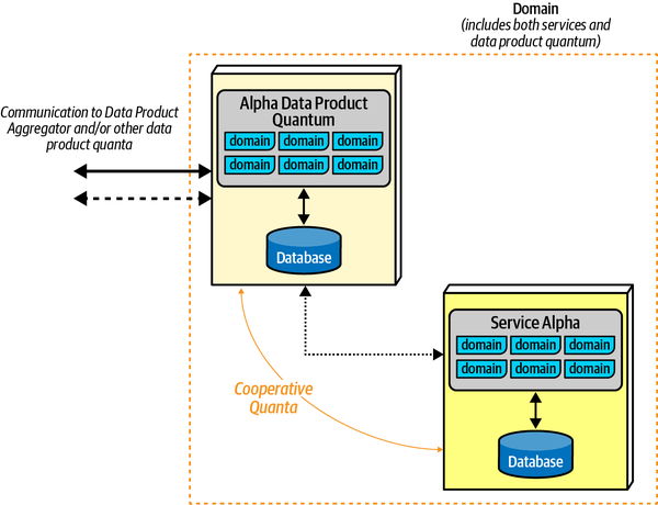
Figure 14-1. Structure of a data product quantum
In this example, the service Alpha contains both behavior and transactional (operational) data. The domain includes a data product quantum, which also contains code and data, and which acts as an interface to the overall analytical and reporting portion of the system. The DPQ acts as an operationally independent but highly coupled set of behaviors and data.
Several types of DPQs commonly exist in modern architectures:
- Source-aligned (native) DPQ
-
Provides analytical data on behalf of the collaborating
architecture quantum, typically a microservice, acting as a cooperative quantum. - Aggregate DQP
- Aggregates data from multiple inputs, either synchronously orasynchronously. For example, for some aggregations, an asynchronous request may be sufficient; for others, the aggregator DPQ may need to perform synchronous queries for a source-aligned DPQ.
- Fit-for-purpose DPQ
- A custom-made DPQ to serve a particular requirement, whichmay encompass analytical reporting, business intelligence, machine learning, or other supporting capability.
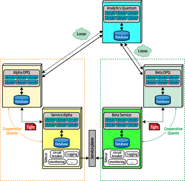
Figure 14-2. The data product quantum acts as a separate but highly coupled adjunct to a service
Here, the DPQ represents a component owned by the domain team responsible for implementing the service. It overlaps information stored in the database, and may have interactions with some of the domain behavior asynchronously. The data product quantum also likely has behavior as well as data for the purposes of analytics and business intelligence.
Each data product quantum acts as a cooperative quantum for the service itself:
- Cooperative quantum
-
An operationally separate quantum that communicates with its
cooperator via asynchronous communication and eventual consistency, yet features tight contract coupling with its cooperator and generally looser contract coupling to the analytics quantum, the service responsible for reports, analysis, business intelligence, and so on. While the two cooperating quanta are operationally independent, they represent two sides of data: operational data in the quantum and analytical data in the data product quantum.
Data Mesh, Coupling, and Architecture Quantum
When to Use Data Mesh
Like all things in architecture, this pattern has trade-offs
It is most suitable in modern distributed architectures such as microservices with well-contained transactionality and good isolation between services. It allows domain teams to determine the amount, cadence, quality, and transparency of the data consumed by other quanta.
It is more difficult in architectures where analytical and operational data must stay in sync at all times, which presents a daunting challenge in distributed architectures. Finding ways to support eventual consistency, perhaps with very strict contracts, allows many patterns that don’t impose other difficulties.
Data mesh is an outstanding example of the constant incremental evolution that occurs in the software development ecosystem; new capabilities create new perspectives, which in turn help address some persistent headaches from the past, such as the artificial separation of domain from data, both operational and analytical.
Sysops Squad Saga: Data Mesh
Friday, June 10, 09:55
“I just returned from a meeting with our data scientists, and they are trying to figure out a way we can solve a long-term problem for us—we need to become data-driven in expert supply planning, for skill sets demand for different geographical locations at different points in time. That capability will help recruitment, training, and other supply-related functions,” said Logan.
“I haven’t been involved in much of the data mesh implementation—how far along are we?” asked Addison.

Figure 14-3. Ticket Management Domain, including two services with their own DPQs, with a Tickets DPQ
Logan said, “Tickets DPQ is its own architecture quantum, and acts as an aggregation point for a couple of different ticket views that other systems care about.”
“How much does each team have to build versus already supplied?” Addison asked.
“I can answer that,” said Dana. “The data mesh platform team is supplying the data users and data product developers with a set of self-serve capabilities. That allows any team that wants to build a new analytical use case to search and find the data products of choice within existing architecture quanta, directly connect to them, and start using them. The platform also supports domains that want to create new data products. The platform continuously monitors the mesh for any data product downtimes, or incompatibility with the governance policies and informs the domain teams to take actions.”
Logan said, “The domain data product owners in collaboration with security, legal, risk, and compliance SMEs, as well as the platform product owners, have formed a global federated governance group, which decides on aspects of the DPQs that must be standardized, such as their data-sharing contracts, modes of asynchronous transport of data, access control, and so on. The platform team, over a span of time, enriches the DPQ’s sidecar with new policy execution capabilities and upgrades the sidecars uniformly across the mesh.”
“Wow, we’re further along that I thought,” said Dana. “What data do we need in order to supply the information for the expert supply problem?”
Logan replied, “In collaboration with the data scientists, we have determined what information we need to aggregate. It looks like we have the correct information: the Tickets DPQ serves the long-term view of all tickets raised and resolved, the User Maintenance DPQ provides daily snapshots for all expert profiles, and the Survey DPQ provides a log of all survey results from customers.”
“Awesome,” said Addison. “Perhaps we should create a new DPQ named something like Experts Supply DPQ, which takes asynchronous inputs from those three DPQs? Its first product can be called supply recommendations, which uses an ML model trained using data aggregated from DPQs in surveys, tickets, and maintenance domains. The Experts Supply DPQ will provide daily recommendations data, as new data becomes available about tickets, surveys and expert profiles. The overall design looks like Figure 14-4.”
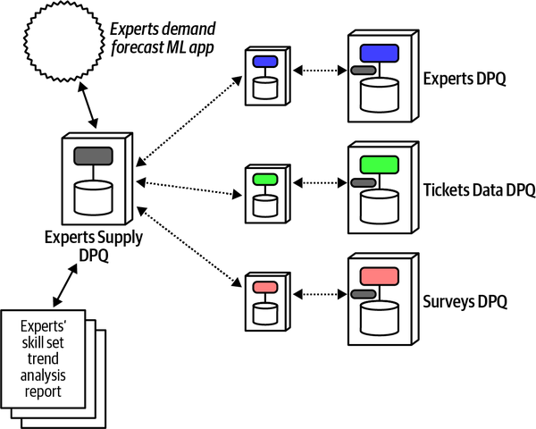
Figure 14-4. Implementing the Experts Supply DPQ
“OK, that looks perfectly reasonable,” said Dana. “The services are already done; we just have to make sure the specific endpoints exist in each of the source DPQs, and implement the new Experts Supply DPQ.”
“That’s right,” said Logan. “One thing we need to worry about, though—trend analysis depends on reliable data. What happens if one of the feeder source systems returns incomplete information for a chunk of time? Won’t that throw off the trend analysis?”
“That’s correct—no data for a time period is better than incomplete data, which makes it seem like there was less traffic than there was,” Dana said. “We can just exempt an empty day, as long as it doesn’t happen much.”
“OK, Addison, you know what than means, right?” Logan said.
“Yes, I certainly do—an ADR that specifies complete information or none, and a fitness function to make sure we get complete data.”
ADR: Ensure that Expert Supply DPQ Sources Supply an Entire Day’s Data or None
Context
The Expert Supply DPQ performs trend analysis over specified time periods. Incomplete data for a particular day will skew trend results and should be avoided.Decision
We will ensure that each data source for the Expert Supply DPQ receives complete snapshots for daily trends or no data for that day, allowing data scientists to exempt that day.The contracts between source feeds and the Expert Supply DPQ should be loosely coupled to prevent brittleness.
Consequences
If too many days become exempt because of availability or other problems, accuracy of trends will be negatively impacted.Fitness functions:
Complete daily snapshot. Check timestamps on messages as they arrive. Given typical message volume, any gap of more than one minute indicates a gap in processing, marking that day as exempt.
Consumer-driven contract fitness function for Ticket DPQ and Expert Supply DPQ. To ensure that internal evolution of the Ticket Domain doesn’t break the Experts Supply DPQ.
Chapter 15. Build Your Own Trade-Off Analysis
Monday, June 10, 10:01
The conference room somehow seemed more brightly lit than it did on that fateful day
“Well,” said Bailey, the main business sponsor and head of the Sysops Squad ticketing application, “I suppose we should get things started. As you know, the purpose of this meeting is to discuss how the IT department was able to turn things around and repair what was nine months ago a train wreck.”
“We call that a retrospective,” said Addison. “And it’s really useful for discovering how to do things better in the future, and to also discuss things that seemed to work well.”
“So then, tell us, what worked really well? How did you turn this business line around from a technical standpoint?” asked Bailey.
“It really wasn’t one single thing,” said Austen, “but rather a combination of a lot of things. First of all, we in IT learned a valuable lesson about looking at the business drivers as a way to address problems and create solutions. Before, we always used to focus only on the technical aspects of a problem, and as a result never saw the big picture.”
“That was one part of it,” said Dana, “but one of the things that turned things around for me and the database team was starting to work together more with the application teams to solve problems. You see, before, those of us on the database side of things did our own thing, and the application development teams did their own thing. We never would have gotten to where we are now without collaborating and working together to migrate the Sysops Squad application.”
“For me it was learning how to properly analyze trade-offs,” said Addison. “If it weren’t for Logan’s guidance, insights, and knowledge, we wouldn’t be in the shape we’re in now. It was because of Logan that we were able to justify our solutions from a business perspective.”
“About that,” said Bailey, “I think I speak for everyone here when I say that your initial business justifications were what prompted us to give you one last shot at repairing the mess we were in. That was something we weren’t accustomed to, and, well, quite frankly it took us by surprise—in a good way.”
“OK,” said Parker, “so now that we all agree things seem to be going well, how do we keep this pace going? How do we encourage other departments and divisions within the company from getting into the same mess we were in before?”
“Discipline,” said Logan. “We continue our new habit of creating trade-off tables for all our decisions, continue documenting and communicating our decisions through architecture decision records, and continue collaborating with other teams on problems and solutions.”
“But isn’t that just adding a lot of extra process and procedures to the mix?” asked Morgan, head of the marketing department.
“No,” said Logan. “That’s architecture. And as you can see, it works.”
To that end, this chapter provides some advice on how to build your own trade-off analysis, using many of the same techniques we used to derive the conclusions presented in this book.
Our three-step process for modern trade-off analysis, which we introduced in Chapter 2 is as follows:
-
Find what parts are entangled together.
-
Analyze how they are coupled to one another.
-
Assess trade-offs by determining the impact of change to interdependent systems.
We discuss some techniques and considerations for each step next.
Finding Entangled Dimensions
An architect’s first step in this process is to discover what dimensions are entangled, or braided, together. This is unique within a particular architecture but discoverable by experienced developers, architects, operations folks, and other roles familiar with the existing overall ecosystem and its capabilities and constraints.
Coupling
The first part of the analysis answers this question for an
For example, to create a static coupling diagram for a microservice within an architecture, an architect needs to gather the following details:
-
Operating systems/container dependencies
-
Dependencies delivered via transitive dependency management (frameworks, libraries, etc.)
-
Persistence dependencies on databases, search engines, cloud environments, etc.
-
Architecture integration points required for the service to bootstrap itself
-
Messaging infrastructure (such as a message broker) required to enable communication to other quanta
The static coupling diagram does not consider other quanta whose only coupling point is workflow communication with this quantum. For example, if an AssignTicket Service cooperates with the ManageTicket within a workflow but has no other coupling points, they are statically independent (but dynamically coupled during the actual workflow).
Teams that already have most of their environments built via automation can build into that generative mechanism an extra capability to document the coupling points as the system builds.
This process highlights the importance of iterative design in architecture. No architect is so brilliant that their first draft is always perfect. Building sample topologies for workflows (much as we do in this book) allows an architect or team to build a matrix view of trade-offs, allowing quicker and more thorough analysis than ad hoc approaches.
Analyze Coupling Points
| Parallel Saga | Ratings |
|---|---|
Communication | Asynchronous |
Consistency | Eventual |
Coordination | Centralized |
Coupling | Low |
Complexity | Low |
Responsiveness/availability | High |
Scale/elasticity | High |
When building these ratings lists, we considered each design solution (our named patterns) in isolation, combining them only at the end to see the differences, shown in Table 15-2.
Assess Trade-Offs
Trade-Off Techniques
Over time, the authors have created a number of trade-off analyses and have built up some advice on how to approach them.
Qualitative Versus Quantative Analysis
Similarly, architects within a particular organization can carry out the same exercise, building a dimensional matrix of coupled concerns, and look at representative examples (either within the existing organization or localized spikes to test theories).
We recommend you hone the skill of performing qualitative analysis, as few opportunities for true quantitative analysis exist in architecture.
MECE Lists
It is important for architects to be sure they are comparing the
A useful concept borrowed from the technology strategy world to help architects get the correct match of things to compare is a MECE list, an acronym for mutually exclusive, collectively exhaustive:
- Mutually exclusive
-
None of the capabilities can overlap between the compared items. As in the preceding example, it is invalid to compare a message queue to an entire ESB because they aren’t really the same category of thing. If you want to compare just the messaging capabilities absent the other parts, that reduces the comparison to two mutually comparable things.
- Collectively exhaustive
-
This suggests that you’ve covered all the possibilities in the decision space, and that you haven’t left out any obvious capabilities. For example, if a team of architects is evaluating high-performance message queues and consider only an ESB and simple message queue but not Kafka, they haven’t considered all the possibilities in the space.
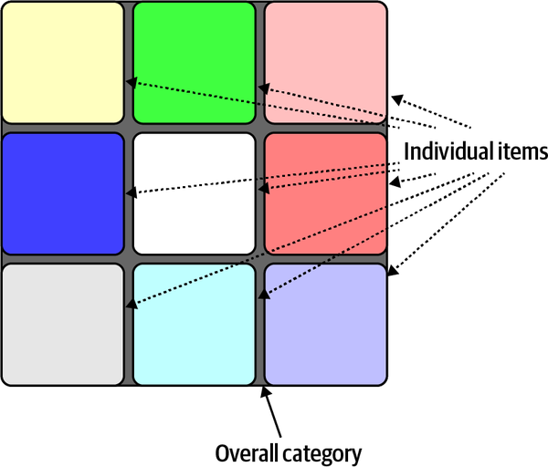
Figure 15-1. A MECE list is mutually exclusive and collectively exhaustive
The software development ecosystem constantly evolves, uncovering new capabilities along the way. When making a decision with long-term implications, an architect should make sure a new capability hasn’t just arrived that changes the criteria. Ensuring that comparison criteria is collectively exhaustive encourages that exploration.
The “Out-of-Context” Trap
When assessing trade-offs, architects must make sure to keep the decision in context;
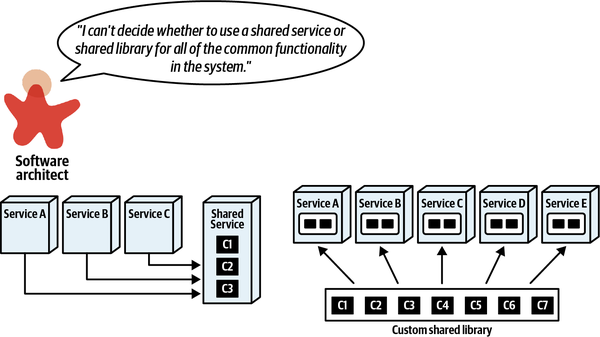
Figure 15-2. Deciding between shared service or library in a distributed architecture
The architect facing this decision will begin to study the two possible solutions, both via general characteristics discovered through research and via experimental data from within their organization. The results of that discovery process lead to a trade-off matrix such as the one shown in Figure 15-3.
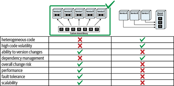
Figure 15-3. Trade-off analysis for two solutions
The architect seems justified in choosing the shared library approach, as the matrix clearly favors that solution…overall. However, this decision exemplifies the out-of-context problem—when the extra context for the problem becomes clear, the decision criteria changes, as illustrated in Figure 15-4.
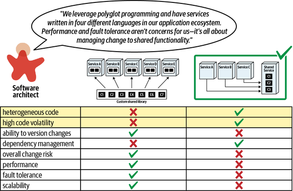
Figure 15-4. Shifting decision based on additional context
The architect continued to research not only the generic problem of service versus library, but the actual context that applies in this situation. Remember, generic solutions are rarely useful in real-world architectures without applying additional situation-specific context.
This process emphasizes two important observations. First, finding the best context for a decision allows the architect to consider fewer options, greatly simplifying the decision process. One common piece of advice from software sages is “embrace simple designs,” without ever explaining how to achieve that goal. Finding the correct narrow context for decisions allows architects to think about less, in many cases simplifying design.
Second, it’s critical for architects to understand the importance of iterative design in architecture, diagramming sample architectural solutions to play qualitative “what-if” games to see how architecture dimensions impact one another. Using iterative design, architects can investigate possible solutions and discover the proper context in which a decision belongs.
Model Relevant Domain Cases
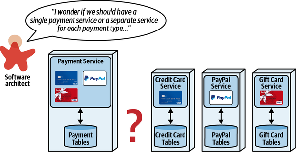
Figure 15-5. Choosing between a single payment service or one per payment type
As we discussed in Chapter 7, architects can choose from a number of integrators and disintegrators to assist this decision. However, those forces are generic—an architect may add more nuance to the decision by modeling some likely scenarios.
For example, consider the first scenario, illustrated in Figure 15-6, to update a credit card processing service.
In this scenario, having separate services provides better maintainability, testability, and deployability, all based on quantum-level isolation of the services. However, the downside of separate services is often duplicated code to prevent static quantum coupling between the services, which damages the benefit of having separate services.
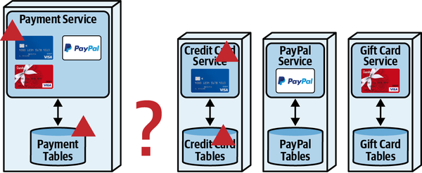
Figure 15-6. Scenario 1: update credit card processing service
In the second scenario, the architect models what happens when the system adds a new payment type, as shown in Figure 15-7.
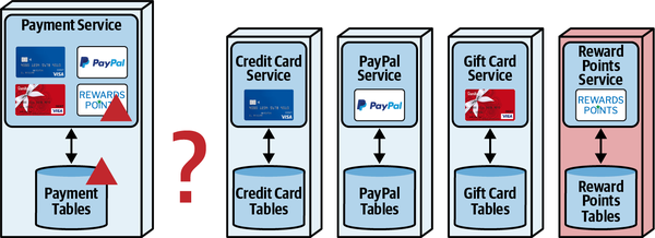
Figure 15-7. Scenario 2: adding a payment type
The architect adds a reward points payment type to see what impact it has on the architecture characteristics of interest, highlighting extensibility as a benefit of separate services. So far, separate services look appealing.
However, as in many cases, more complex workflows highlight the difficult parts of the architecture, as shown in the third scenario in Figure 15-8.
In this scenario, the architect starts gaining insight into the real trade-offs involved in this decision. Utilizing separate services requires coordination for this workflow, best handled by an orchestrater. However, as we discussed in Chapter 11, moving to an orchestrator likely impacts performance negatively and makes data consistency more of a challenge. The architect could avoid the orchestrator, but the workflow logic must reside somewhere—remember, semantic coupling can only be increased via implementation, never decreased.
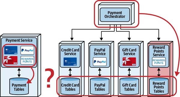
Figure 15-8. Scenario 3: using multiple types for payment
Having modeled these three scenarios, the architect realizes that the real trade-off analysis comes down to which is more important: performance and data consistency (a single payment service) or extensibility and agility (separate services).
Thinking about architecture problems in the generic and abstract gets an architect only so far. As architecture generally evades generic solutions, it is important for architects to build their skills in modeling relevant domain scenarios to home in on better trade-off analysis and decisions.
Prefer Bottom Line over Overwhelming Evidence
Rather than show all the information they have gathered, an architect should reduce the trade-off analysis to a few key points, which are sometimes aggregates of individual trade-offs.
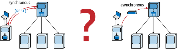
Figure 15-9. Deciding between communication types
The synchronous solution orchestrator makes synchronous REST calls to communicate with workflow collaborators, whereas the asynchronous solution uses message queues to implement asynchronous communication.
After considering the generic factors that point to one versus the other, the architect next thinks about specific domain scenarios of interest to nontechnical stakeholders. To that end, the architect will build a trade-off table that resembles Table 15-3.
After modeling these scenarios, the architect can create a bottom-line decision for the stakeholders: which is more important, a guarantee that the credit approval process starts immediately or responsiveness and fault-tolerance? Eliminating confusing technical details allows the nontechnical domain stakeholders to focus on outcomes rather than design decisions, which help avoids drowning them in a sea of details.
Avoiding Snake Oil and Evangelism
One unfortunate side effect of enthusiasm for technology is
Trouble comes because, when someone evangelizes a tool, technique, approach, or anything else people build enthusiasm for, they start enhancing the good parts and diminishing the bad parts. Unfortunately, in software architecture, the trade-offs always eventually return to complicate things.
An architect should also be wary of any tool or technique that promises any shocking new capabilities, which come and go on a regular basis. Always force evangelists for the tool or technique to provide an honest assessment of the good and bad—nothing in software architecture is all good—which allows a more balanced decision.
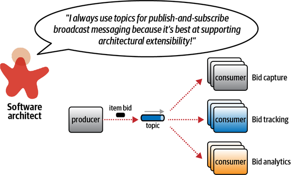
Figure 15-10. An architect evangelist who thinks they have found a silver bullet
This architect has likely worked on problems in the past where extensibility was a key driving architecture characteristic and believes that capability will always drive the decision process. However, solutions in architecture rarely scale outside narrow confines of a particular problem space. On the other hand, anecdotal evidence is often compelling. How do you get to the real trade-off hiding behind the knee-jerk evangelism?
While experience is useful, scenario analysis is one of an architect’s most powerful tools to allow iterative design without building whole systems. By modeling likely scenarios, an architect can discover if a particular solution will, in fact, work well.
In the example shown in Figure 15-10, an existing system uses a single topic to broadcast changes. The architect’s goal is to add bid history to the workflow—should the team keep the existing publish-and-subscribe approach or move to point-to-point messaging for each consumer?
To discover the trade-offs for this specific problem, the architect should model likely domain scenarios using the two topologies. Adding bid history to the existing publish-and-subscribe design appears in Figure 15-11.
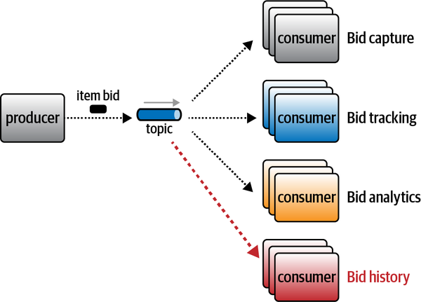
Figure 15-11. Scenario 1: Adding bid history to the existing topic
While this solution works, it has issues. First, what if the teams need different contracts for each consumer? Building a single large contract that encompasses everything implements the “Stamp Coupling for Workflow Management” anti-pattern; forcing each team to unify on a single contract creates an accidental coupling point in the architecture—if one team changes its required information, all the teams must coordinate on that change. Second, what about data security? Using a single publish-and-subscribe topic, each consumer has access to all the data, which can create both security problems and PII (Personally Identifiable Information, discussed in Chapter 14) issues as well. Third, the architect should consider the operational architecture characteristic differences between the different consumers. For example, if the operations team wanted to monitor queue depth and use auto-scaling for bid capture and bid tracking but not for the other two services, using a single topic prevents that capability—the consumers are now operationally coupled together.
To mitigate these shortcomings, the architect should model the alternative solution to see if it addresses the preceding problems (and doesn’t introduce new intractable ones). The individual queue version appears in Figure 15-12.
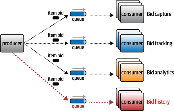
Figure 15-12. Using individual queues to capture bid information
Each part of this workflow (bid capture, bid tracking, bid analytics, and bid history) utilizes its own message queues and addresses many of the preceding problems. First, each consumer can have their own contract, decoupling the consumers from each other. Second, security access and control of data resides within the contract between the producer and each consumer, allowing differences in both information and rate of change. Third, each queue can now be monitored and scaled independently.
Of course, by this point in the book, you should realize that the point-to-point based system isn’t perfect either but offers a different set of trade-offs.
Once the architect has modeled both approaches, it seems that the differences boil down to the choices shown in Table 15-4.
In the end, the architect should consult with interested parties (operations, enterprise architects, business analysts, and so on) to determine which of these sets of trade-offs is more important.
Sometimes an architect doesn’t choose to evangelize something but is rather coerced into playing an opposite foil, particularly for something that has no clear advantage. Technologies develop fans, sometimes fervent ones, who tend to downplay disadvantages and enhance upsides.
For example, recently a tech lead on a project tried to wrangle one of the authors into an argument about
Instead, the architect pointed out that it was a trade-off, gently explaining that many of the advantages touted by the tech lead required a level of discipline that had never manifested within the team in the past, but will surely improve.
Rather than be forced into taking the opposing position, instead the architect forced a real-world trade-off analysis, not based on generic solutions. The architect agreed to try the Monorepo approach but also gather metrics to make sure that the negative aspects of the solution didn’t manifest. For example, one of the damaging anti-patterns they wanted to avoid was accidental coupling between two projects because of repository proximity, so the architect and team built a series of fitness functions to ensure that, while technically possible to create a coupling point, the fitness function prevented it.
Tip
Don’t allow others to force you into evangelizing something—bring it back to trade-offs.
We advise architects to avoid evangelizing and to try to become the objective arbiter of trade-offs. An architect adds real value to an organization not by chasing silver bullet after silver bullet but rather by honing their skills at analyzing the trade-offs as they appear.
Sysops Squad Saga: Epilogue
Monday, June 20, 16:55
“OK, I think I finally get it. We can’t really rely on generic advice
“That’s correct. But it’s not a disadvantage—it’s an advantage. Once we all learn how to isolate dimensions and perform trade-off analysis, we’re learning concrete things about our architecture. Who cares about other, generic ones? If we can boil the number of trade-offs for a problem down to a small enough number to actually model and test them, we gain invaluable knowledge about our ecosystem. You know, structural engineers have built a ton of math and other predictive tools, but building their stuff is difficult and expensive. Software is a lot…well, softer. I’ve always said that testing is the engineering rigor of software development. While we don’t have the kind of math other engineers have, we can incrementally build and test our solutions, allowing much more flexibility and leveraging the advantage of a more flexible medium. Testing with objective outcomes allows our trade-off analyses to go from qualitative to quantitative—from speculation to engineering. The more concrete facts we can learn about our unique ecosystem, the more precise our analysis can become.”
“Yeah, that makes sense. Want to go to the after-work gathering to celebrate the big turnaround?”
“Sure.”
Appendix A. Concept and Term References
In this book, we’ve made several references to terms or concepts that are explained in detail in our
Cyclomatic complexity: Chapter 6, page 81
Component coupling: Chapter 7, page 92
Component cohesion: Chapter 7, page 93
Technical versus domain partitioning: Chapter 8, page 103
Layered architecture: Chapter 10, page 135
Service-based architecture: Chapter 13, page 163
Microservices architecture: Chapter 12, page 151
Appendix B. Architecture Decision Record References
Each Sysops Squad decision in this book was accompanied by a corresponding Architecture Decision Record. We consolidated all the ADRs here for easy reference:
“ADR: A short noun phrase containing the architecture decision”
“ADR: Migrate Sysops Squad Application to a Distributed Architecture”
“ADR: Migration Using the Component-Based Decomposition Approach”
“ADR: Use of Document Database for Customer Survey”
“ADR: Consolidated Service for Ticket Assignment and Routing”
“ADR: Consolidated Service for Customer-Related Functionality”
“ADR: Using a Sidecar for Operational Coupling”
“ADR: Use of a Shared Library for Common Ticketing Database Logic”
“ADR: Single Table Ownership for Bounded Contexts”
“ADR: Survey Service Owns the Survey Table”
“ADR: Use of In-Memory Replicated Caching for Expert Profile Data”
“ADR: Use Orchestration for Primary Ticket Workflow”
“ADR: Loose Contract for Sysops Squad Expert Mobile Application”
Appendix C. Trade-Off References
The primary focus of this book is trade-off analysis; to that end, we created a number of trade-off tables and figures in Part II to summarize trade-offs around a particular architecture concern. This appendix summarizes all the trade-off tables and figures for easy reference:
Figure 6-25, “Relational databases rated for various adoption characteristics”
Figure 6-26, “Key-value databases rated for various adoption characteristics”
Figure 6-27, “Document databases rated for various adoption characteristics”
Figure 6-28, “Column family databases rated for various adoption characteristics”
Figure 6-30, “Graph databases rated for various adoption characteristics”
Figure 6-31, “New SQL databases rated for various adoption characteristics”
Figure 6-32, “Cloud native databases rated for various adoption characteristics”
Figure 6-33, “Time-series databases rated for various adoption characteristics”
Table 8-1, “Trade-offs for the code replication technique”
Table 8-2, “Trade-offs for the shared library technique”
Table 8-3, “Trade-offs for the shared service technique”
Table 8-4, “Trade-offs for the Sidecar pattern / service mesh technique”
Table 9-1, “Joint ownership table split technique trade-offs”
Table 9-2, “Joint ownership data-domain technique trade-offs”
Table 9-3, “Joint ownership delegate technique trade-offs”
Table 9-4, “Joint ownership service consolidation technique trade-offs”
Table 9-5, “Background synchronization pattern trade-offs”
Table 9-6, “Orchestrated request-based pattern trade-offs”
Table 9-7, “Event-based pattern trade-offs”
Table 10-1, “Trade-offs for the Interservice Communication data access pattern”
Table 10-2, “Trade-offs for the Column Schema Replication data access pattern”
Table 10-3, “Trade-offs associated with the replicated caching data access pattern”
Table 10-4, “Trade-offs associated with the data domain data access pattern”
Table 11-1, “Trade-offs for orchestration”
Table 11-2, “Trade-offs for the Front Controller pattern”
Table 11-3, “Stateless choreography trade-offs”
Table 11-4, “Stamp coupling trade-offs”
Table 11-5, “Trade-offs for the choreography communication style”
Table 11-6, “Trade-off between orchestration and choreography for ticket workflow”
Table 11-7, “Updated trade-offs between orchestration and choreography for ticket workflow”
Table 11-8, “Final trade-offs between orchestration and choreography for ticket workflow”
Table 12-12, “Trade-offs associated with atomic distributed transactions and compensating updates”
Table 13-1, “Trade-offs for strict contracts”
Table 13-2, “Trade-offs for loose contracts”
Table 13-3, “Trade-offs for consumer-driven contracts”
Table 13-4, “Trade-offs for stamp coupling”
Table 14-1, “Trade-offs for the Data Warehouse pattern”
Table 14-2, “Trade-offs for the Data Lake pattern”
Table 14-3, “Trade-offs for the Data Mesh pattern”
Table 15-2, “Consolidated comparison of dynamic coupling patterns”
Table 15-4, “Trade-offs between point-to-point versus publish-and-subscribe messaging”
Index
A
- abstractness of codebase, Abstractness and Instability
- distance from main sequence, Distance from the Main Sequence
- ACID (atomicity, consistency, isolation, durability) transactions
- about, Distributed Transactions-Distributed Transactions
- distributed transactions versus, Distributed Transactions
- example, Distributed Transactions
- BASE transactions versus, Distributed Transactions
- database types
- cloud native databases, Cloud Native Databases
- document databases, Document Databases
- graph databases, Graph Databases
- NewSQL databases, NewSQL Databases
- relational databases, Relational Databases, Relational Databases
- time series databases, Time-Series Databases
- about, Distributed Transactions-Distributed Transactions
- afferent coupling, Afferent and Efferent Coupling, Abstractness and Instability
- aggregate orientation, Relational Databases
- GraphQL read-only aggregated data, Strict Versus Loose Contracts
- key-value databases, Key-Value Databases
- NoSQL databases understanding, Column Family Databases
- agility
- modularity providing, Architectural Modularity, Modularity Drivers
- speed-to-market via, Modularity Drivers
- testability for, Testability
- versioning shared libraries, Versioning Strategies
- Amazon DynamoDB key-value database, Key-Value Databases
- Ambler, Scott, Decomposing Monolithic Data
- analytical data
- about, The Importance of Data in Architecture, Managing Analytical Data
- data meshes, The Data Mesh-When to Use Data Mesh
- analytical reporting coupled, Data Mesh, Coupling, and Architecture Quantum
- when to use, When to Use Data Mesh
- definition, The Importance of Data in Architecture
- domain over technical partitioning, The Data Lake
- previous approaches
- data lakes, The Data Lake-The Data Lake
- data warehouses, The Data Warehouse-The Data Warehouse
- Sysops Squad saga, Managing Analytical Data, The Data Warehouse, The Data Lake
- annotations
- distributed transaction management, Techniques for Managing Sagas
- metadata for, Code Replication
- Anthology Saga pattern, Anthology Saga(aec) Pattern-Anthology Saga(aec) Pattern
- Apache Cassandra column family database, Column Family Databases
- Apache Ignite replicated caching, Replicated Caching Pattern
- APIs
- endpoint versioning for shared services, Change Risk
- platforms for code reuse, Reuse via Platforms
- Architectural Decision Records (ADRs), Architectural Decision Records
- architectural decomposition
- about, Architectural Decomposition
- eating the elephant, Architectural Decomposition
- codebase analysis
- about, Is the Codebase Decomposable?
- abstractness and instability, Abstractness and Instability
- afferent and efferent coupling, Afferent and Efferent Coupling
- distance from main sequence, Distance from the Main Sequence
- component-based, Component-Based Decomposition-Component-Based Decomposition
- about, Architectural Decomposition, Component-Based Decomposition Patterns
- about patterns, Component-Based Decomposition, Component-Based Decomposition Patterns
- architecture stories, Component-Based Decomposition Patterns
- create component domains, Create Component Domains Pattern-Fitness function: All namespaces under <root namespace node> should be restricted to <list of domains>
- create domain services, Create Domain Services Pattern-Fitness function: All components in <some domain service> should start with the same namespace
- determine component dependencies, Determine Component Dependencies Pattern-Fitness function: <some component> should not have a dependency on <another component>
- flatten components, Flatten Components Pattern-Fitness function: No source code should reside in a root namespace
- gather common domain components, Gather Common Domain Components Pattern-Fitness function: Find common code across components
- identify and size components, Identify and Size Components Pattern-Sysops Squad Saga: Sizing Components
- services built from components, Component-Based Decomposition
- data
- about, Pulling Apart Operational Data
- about decomposing monolithic, Decomposing Monolithic Data
- assign tables to data domains, Step 2: Assign Tables to Data Domains-Step 2: Assign Tables to Data Domains
- create data domains, Step 1: Analyze Database and Create Data Domains
- drivers of decomposition, Data Decomposition Drivers-Database transactions
- Refactoring Databases (Ambler and Sadalage), Decomposing Monolithic Data
- schemas to separate servers, Step 4: Move Schemas to Separate Database Servers
- separate connections to data domains, Step 3: Separate Database Connections to Data Domains
- switch over to independent servers, Step 5: Switch Over to Independent Database Servers
- Sysops Squad saga, Sysops Squad Saga: Justifying Database Decomposition
- tactical forking, Component-Based Decomposition-Trade-Offs
- about, Architectural Decomposition
- trade-offs, Trade-Offs
- volatility-based decomposition, Code Volatility
- about, Architectural Decomposition
- architectural fitness functions (see fitness functions for governance)
- architecture
- architecture governance, Architecture Fitness Functions
- Big Ball of Mud anti-pattern, Is the Codebase Decomposable?
- Equifax data breach, Using Fitness Functions
- fitness functions, Using Fitness Functions
- (see also fitness functions)
- architecture quantum, Architecture (Quantum | Quanta)
- (see also architecture quantum)
- brittleness, Code Reuse: When Does It Add Value?
- data warehouses, The Data Warehouse
- strict contracts creating, Strict Versus Loose Contracts
- composition versus inheritance, Shared Service
- data importance, The Importance of Data in Architecture
- (see also data)
- definitions of terms, Architecture Versus Design: Keeping Definitions Simple
- architecture definition, Why “The Hard Parts”?
- design versus, Architecture Versus Design: Keeping Definitions Simple-Architecture Versus Design: Keeping Definitions Simple
- security controlled through design, Sysops Squad Saga: Customer Registration Granularity
- evolution of, Giving Timeless Advice About Software Architecture, Architecture Fitness Functions, Architectural Modularity
- (see also modularity)
- iterative nature of analysis, Analyze Coupling Points
- why more important than how, Architecture Versus Design: Keeping Definitions Simple
- architecture governance, Architecture Fitness Functions
- architecture governance, Architecture Fitness Functions
- Big Ball of Mud anti-pattern, Is the Codebase Decomposable?
- Equifax data breach, Using Fitness Functions
- fitness functions, Using Fitness Functions
- (see also fitness functions)
- architecture quantum
- about, Architecture (Quantum | Quanta), Architectural quantum
- coupling, static versus dynamic, Architecture (Quantum | Quanta)
- dynamic quantum coupling, Dynamic Quantum Coupling-Coordination
- high static coupling, High Static Coupling-High Static Coupling
- user interface, High Static Coupling
- data disintegration driver, Architectural quantum
- separate databases, Step 4: Move Schemas to Separate Database Servers
- Sysops Squad saga, Sysops Squad Saga: Justifying Database Decomposition
- data product quantum, Definition of Data Mesh-Data Product Quantum
- high functional cohesion, High Functional Cohesion
- database, Architectural quantum
- independently deployable, Independently Deployable
- Sysops Squad saga, Sysops Squad Saga: Understanding Quanta
- architecture stories, Component-Based Decomposition Patterns
- ArchUnit tool, Fitness function: All components in <some domain service> should start with the same namespace
- Aslett, Matthew, NewSQL Databases
- asynchronous communication
- about complexity of, Fantasy Fiction Saga(aao) Pattern, Horror Story(aac) Pattern
- definition, Architecture Versus Design: Keeping Definitions Simple
- delegate technique of data ownership, Delegate Technique
- distributed data access, Column Schema Replication Pattern
- fault tolerance, Availability/Fault Tolerance
- performance issues, Performance
- messaging mitigating, Performance
- publish-and-subscribe messaging, Event-Based Pattern
- dead letter queue, Event-Based Pattern
- durable subscribers, Event-Based Pattern
- synchronous versus, Communication, Sysops Squad Saga: Understanding Quanta
- atomic fitness functions, Using Fitness Functions
- atomic workflow
- consistency, Consistency
- definition, Architecture Versus Design: Keeping Definitions Simple
- eventual consistency versus, Architecture Versus Design: Keeping Definitions Simple, Consistency
- atomicity in ACID transactions, Distributed Transactions
- distributed transactions versus, Distributed Transactions
- attributes for distributed transaction management, Techniques for Managing Sagas
- availability
- basic availability of BASE transactions, Distributed Transactions
- coupling relationship, Analyze Coupling Points
- database types
- about availability, Selecting a Database Type
- cloud native databases, Cloud Native Databases
- column family databases, Column Family Databases
- document databases, Document Databases
- graph databases, Graph Databases
- key-value databases, Key-Value Databases
- NewSQL databases, NewSQL Databases
- relational databases, Relational Databases
- time series databases, Time-Series Databases
- modularity and, Availability/Fault Tolerance
- AWS Redshift cloud native database, Cloud Native Databases
- Azure CosmosDB cloud native database, Cloud Native Databases
B
- backpressure information link, Sysops Squad Saga: Ticket Assignment Granularity
- backup and restore databases, Step 4: Move Schemas to Separate Database Servers
- bandwidth and stamp coupling, Bandwidth
- BASE (basic availability, soft state, eventual consistency) transactions, Distributed Transactions
- Beck, Kent, Architecture Fitness Functions
- Berners-Lee, Tim, The Importance of Data in Architecture
- best practices nonexistent, What Happens When There Are No “Best Practices”?
- Big Ball of Mud anti-pattern, Is the Codebase Decomposable?
- tactical forking, Component-Based Decomposition-Trade-Offs
- bounded context in microservices, The Importance of Data in Architecture, Discerning Coupling in Software Architecture, Change control
- architecture quanta, High Static Coupling
- architecture quantum versus, Sysops Squad Saga: Understanding Quanta
- breaking database changes controlled, Change control-Change control
- database abstraction, Change control-Change control
- data domains, Decomposing Monolithic Data
- combining data domains, Step 2: Assign Tables to Data Domains
- data requirement in some architectures, Pulling Apart Operational Data
- data sovereignty per service, Step 3: Separate Database Connections to Data Domains
- granularity and, Data Relationships
- high functional cohesion, High Functional Cohesion
- ownership of data (see ownership of data)
- breaking changes to data structure, Change control
- bounded context controlling, Change control-Change control
- database abstraction, Change control-Change control
- bounded context controlling, Change control-Change control
- brittleness in architecture, Code Reuse: When Does It Add Value?
- data warehouses, The Data Warehouse
- strict contracts creating, Strict Versus Loose Contracts
- broker style event-driven architecture quantum, High Static Coupling, Sysops Squad Saga: Understanding Quanta
- Brooks, Fred, What Happens When There Are No “Best Practices”?
- business case for modularity, Sysops Squad Saga: Creating a Business Case-Sysops Squad Saga: Creating a Business Case
C
- caching for distributed data access, Replicated Caching Pattern-Replicated Caching Pattern
- Chain of Responsibility design pattern, Time Travel Saga(sec) Pattern
- The Checklist Manifesto (Gawande), Using Fitness Functions
- choreographed coordination, Choreography Communication Style-Choreography Communication Style
- about coordination, Coordination, Managing Distributed Workflows
- about orchestrated versus, Managing Distributed Workflows, Phone Tag Saga(sac) Pattern
- definition, Architecture Versus Design: Keeping Definitions Simple
- service granularity and, Workflow and Choreography-Workflow and Choreography
- stamp coupling for management, Stamp Coupling for Workflow Management
- workflow state management, Workflow State Management-Workflow State Management
- Front Controller pattern, Workflow State Management
- stamp coupling, Workflow State Management
- stateless choreography, Workflow State Management
- client/server applications, The Data Warehouse
- cloud native databases, Cloud Native Databases
- Cockburn, Alistair, Sidecars and Service Mesh
- CockroachDB NewSQL database, NewSQL Databases
- code replication as reuse pattern, Code Replication-When to Use
- code reuse patterns
- about, Reuse Patterns
- code replication, Code Replication-When to Use
- granularity and shared code, Shared Code-Shared Code, Dependency Management and Change Control
- orthogonal reuse pattern, Sidecars and Service Mesh
- shared libraries
- about, Shared Library
- granularity and, Dependency Management and Change Control
- versioning strategies, Versioning Strategies-When To Use
- shared services, Shared Service-When to Use
- change risk, Change Risk
- fault tolerance, Fault Tolerance
- performance, Performance
- scalability, Scalability
- versioning via API endpoints, Change Risk
- sidecars and service mesh, Sidecars and Service Mesh-When to Use
- Sysops Squad saga, Sysops Squad Saga: Common Infrastructure Logic
- strict contracts and, Strict Versus Loose Contracts
- Sysops Squad saga, Reuse Patterns
- shared domain functionality, Sysops Squad Saga: Shared Domain Functionality
- sidecars and service mesh, Sysops Squad Saga: Common Infrastructure Logic
- value added, Code Reuse: When Does It Add Value?
- reuse via platforms, Reuse via Platforms
- code volatility as granularity driver, Code Volatility
- cohesion
- high functional cohesion, High Functional Cohesion
- database architecture quantum, Architectural quantum
- maintainability and, Maintainability
- metrics information link, Service Scope and Function
- service granularity, Service Scope and Function, Fault Tolerance
- high functional cohesion, High Functional Cohesion
- column family databases, Column Family Databases
- communication
- about synchronous versus asynchronous, Communication, Sysops Squad Saga: Understanding Quanta
- analytical data mesh, Data Mesh, Coupling, and Architecture Quantum
- coordination required, Coordination
- database connection pool, Connection management
- Sysops Squad saga, Sysops Squad Saga: Justifying Database Decomposition
- distributed data access, Column Schema Replication Pattern
- dynamic coupling as, Pulling Things Apart, Architecture (Quantum | Quanta)
- communication dependencies, Architecture (Quantum | Quanta)
- saga pattern matrix, Coordination, Transactional Saga Patterns, Analyze Coupling Points
- east-west communication, Workflow and Choreography-Workflow and Choreography
- interservice communication, Workflow and Choreography-Workflow and Choreography
- API endpoint versioning for shared services, Change Risk
- bounded context data, Data Relationships
- data ownership, Common Ownership Scenario, Delegate Technique
- distributed data access, Interservice Communication Pattern
- performance issues, Performance
- latency with distributed data, Interservice Communication Pattern
- publish-and-subscribe messaging, Event-Based Pattern
- dead letter queue, Event-Based Pattern
- durable subscribers, Event-Based Pattern
- service scalability and elasticity, Scalability
- compensating updates in distributed transactions, Orchestrated Request-Based Pattern, Epic Saga(sao) Pattern
- state management instead, State Management and Eventual Consistency, Saga State Machines
- Sysops Squad saga, Sysops Squad Saga: Atomic Transactions and Compensating Updates-Sysops Squad Saga: Atomic Transactions and Compensating Updates
- competitive advantage as modularity driver, Modularity Drivers
- compile-based versus runtime changes, Change Risk
- component-based decomposition, Component-Based Decomposition-Component-Based Decomposition
- about, Architectural Decomposition, Component-Based Decomposition Patterns
- about components, Component-Based Decomposition
- patterns
- about, Component-Based Decomposition, Component-Based Decomposition Patterns
- architecture stories, Component-Based Decomposition Patterns
- create component domains, Create Component Domains Pattern-Fitness function: All namespaces under <root namespace node> should be restricted to <list of domains>
- create domain services, Create Domain Services Pattern-Fitness function: All components in <some domain service> should start with the same namespace
- determine component dependencies, Determine Component Dependencies Pattern-Fitness function: <some component> should not have a dependency on <another component>
- flatten components, Flatten Components Pattern-Fitness function: No source code should reside in a root namespace
- gather common domain components, Gather Common Domain Components Pattern-Fitness function: Find common code across components
- identify and size components, Identify and Size Components Pattern-Sysops Squad Saga: Sizing Components
- components
- Create Component Domains pattern, Create Component Domains Pattern-Fitness function: All namespaces under <root namespace node> should be restricted to <list of domains>
- fitness functions, Fitness Functions for Governance
- definition, Architecture Versus Design: Keeping Definitions Simple, Maintainability, Component-Based Decomposition, Pattern Description
- dependencies determination, Pattern Description
- Identify and Size Components pattern, Identify and Size Components Pattern-Sysops Squad Saga: Sizing Components
- maintainability and, Maintainability
- names, Pattern Description
- namespaces, Pattern Description
- size determination, Pattern Description
- size and granularity, Service Scope and Function
- Create Component Domains pattern, Create Component Domains Pattern-Fitness function: All namespaces under <root namespace node> should be restricted to <list of domains>
- composite architecture characteristics, Using Fitness Functions
- composition versus inheritance in design, Shared Service
- connection management
- connection quotas, Connection management
- data disintegration driver, Connection management-Connection management
- scalability includes connections, Scalability
- database per service, Scalability
- Sysops Squad saga, Sysops Squad Saga: Justifying Database Decomposition
- consistency
- about, Consistency, Selecting a Database Type
- ACID transactions, Distributed Transactions
- distributed transactions versus, Distributed Transactions
- database types
- cloud native ACID, Cloud Native Databases
- column family tunable, Column Family Databases
- document ACID, Document Databases
- graph ACID, Graph Databases
- key-value tunable, Key-Value Databases
- NewSQL ACID, NewSQL Databases
- relational ACID, Relational Databases
- time series ACID or tunable, Time-Series Databases
- dynamic coupling relationship matrix, Coordination, Transactional Saga Patterns, Analyze Coupling Points
- eventual consistency
- about patterns, Eventual Consistency Patterns
- atomic workflow versus, Architecture Versus Design: Keeping Definitions Simple, Consistency
- background synchronization pattern, Background Synchronization Pattern-Background Synchronization Pattern
- BASE transactions, Distributed Transactions
- event-based pattern, Event-Based Pattern-Event-Based Pattern
- finite state machines for, State Management and Eventual Consistency
- orchestrated request-based pattern, Orchestrated Request-Based Pattern-Orchestrated Request-Based Pattern
- majority quorum, Key-Value Databases, Document Databases
- tunable consistency, Key-Value Databases, Column Family Databases
- Constantine, Larry, Afferent and Efferent Coupling, Putting Things Back Together
- consumer-driven contracts, Consumer-driven contracts
- context for trade-off analysis, The “Out-of-Context” Trap-The “Out-of-Context” Trap
- contracts
- about, Contracts
- bounded context data ownership, Change control-Change control
- contract fidelity and microservices, Coupling levels
- consumer-driven contracts, Consumer-driven contracts
- definition, Architecture Versus Design: Keeping Definitions Simple
- distributed data access
- Data Domain not requiring, Data Domain Pattern
- Interservice Communication requiring, Interservice Communication Pattern, Data Domain Pattern
- Replicated Cache requiring, Data Domain Pattern
- high static coupling, High Static Coupling
- loose contracts, Strict Versus Loose Contracts
- decoupling via, Strict Versus Loose Contracts, Loose contracts
- fitness functions required, Loose contracts
- trade-offs, Loose contracts
- microservice contracts, Contracts in Microservices
- stamp coupling
- about, Stamp Coupling
- bandwidth, Bandwidth
- over-coupling via, Over-Coupling via Stamp Coupling
- workflow management, Stamp Coupling for Workflow Management
- strict contracts, Strict Versus Loose Contracts
- JSON example, Strict Versus Loose Contracts
- trade-offs, Strict contracts
- Sysops Squad saga, Contracts, Sysops Squad Saga: Managing Ticketing Contracts
- cooperative quantum, Data Product Quantum
- coordination of workflow
- about, Coordination, Managing Distributed Workflows
- about trade-offs, Trade-Offs Between Orchestration and Choreography
- choreographed coordination, Choreography Communication Style-Choreography Communication Style
- about orchestration versus, Managing Distributed Workflows, Phone Tag Saga(sac) Pattern
- definition, Architecture Versus Design: Keeping Definitions Simple
- stamp coupling for management, Stamp Coupling for Workflow Management
- workflow state management, Workflow State Management
- dynamic coupling relationship matrix, Coordination, Transactional Saga Patterns, Analyze Coupling Points
- orchestrated coordination, Orchestration Communication Style-Orchestration Communication Style
- about choreographed versus, Managing Distributed Workflows, Phone Tag Saga(sac) Pattern
- definition, Architecture Versus Design: Keeping Definitions Simple
- workflow state management, Workflow State Management
- stamp coupling for management, Stamp Coupling for Workflow Management
- Sysops Squad saga, Managing Distributed Workflows, Sysops Squad Saga: Managing Workflows-Sysops Squad Saga: Managing Workflows
- coupling
- about static versus dynamic, Architecture (Quantum | Quanta)
- dynamic coupling, Pulling Things Apart, Architecture (Quantum | Quanta)
- static coupling, Pulling Things Apart, Architecture (Quantum | Quanta)
- Sysops Squad saga, Sysops Squad Saga: Understanding Quanta
- architectural decomposition
- afferent coupling, Afferent and Efferent Coupling, Abstractness and Instability
- common domain functionality consolidated, Sysops Squad Saga: Gathering Common Components
- determining component dependencies, Pattern Description
- efferent coupling, Afferent and Efferent Coupling, Abstractness and Instability
- architecture quantum, Architecture (Quantum | Quanta), High Static Coupling
- dynamic quantum coupling, Dynamic Quantum Coupling-Coordination
- high static coupling, High Static Coupling-High Static Coupling
- independently deployable, Independently Deployable
- Sysops Squad saga, Sysops Squad Saga: Understanding Quanta
- user interface, High Static Coupling
- availability relationship, Analyze Coupling Points
- data relationships, Data relationships
- definition, Architecture Versus Design: Keeping Definitions Simple, Discerning Coupling in Software Architecture
- interservice communication pattern, Interservice Communication Pattern
- loose contracts for decoupling, Strict Versus Loose Contracts, Loose contracts
- consumer-driven contracts, Consumer-driven contracts
- microservices, Coupling levels
- microservices and contract fidelity, Coupling levels
- strict contract tight coupling, Strict contracts
- maintainability and, Maintainability
- operational coupling, Sidecars and Service Mesh-When to Use
- Sysops Squad saga, Sysops Squad Saga: Common Infrastructure Logic
- orchestration, Orchestration Communication Style
- choreography versus, Phone Tag Saga(sac) Pattern
- orthogonal coupling, Sidecars and Service Mesh
- scaling relationship, Phone Tag Saga(sac) Pattern, Analyze Coupling Points
- semantic coupling, Choreography Communication Style
- implementation coupling, Choreography Communication Style
- stamp coupling, Stamp Coupling for Workflow Management
- stamp coupling
- bandwidth, Bandwidth
- choreography state management, Workflow State Management
- over-coupling via, Over-Coupling via Stamp Coupling
- workflow management, Stamp Coupling for Workflow Management
- trade-off analysis, Discerning Coupling in Software Architecture-Discerning Coupling in Software Architecture, Coupling-Analyze Coupling Points
- coupling points, Analyze Coupling Points
- static coupling diagram, Coupling
- about static versus dynamic, Architecture (Quantum | Quanta)
- Create Component Domains pattern, Create Component Domains Pattern-Fitness function: All namespaces under <root namespace node> should be restricted to <list of domains>
- Create Domain Services pattern, Create Domain Services Pattern-Fitness function: All components in <some domain service> should start with the same namespace
- fitness functions, Fitness Functions for Governance
- Sysops Squad saga, Sysops Squad Saga: Creating Domain Services
- credit card data (see PCI (Payment Card Industry) data)
- custom attributes for distributed transaction management, Techniques for Managing Sagas
- cyclomatic complexity and maintainability, Maintainability
D
- data
- about importance of, The Importance of Data in Architecture
- about operational versus analytical, The Importance of Data in Architecture
- analytical data
- about, The Importance of Data in Architecture, Managing Analytical Data
- data lakes, The Data Lake-The Data Lake
- data meshes, The Data Mesh-When to Use Data Mesh
- data meshes coupled to reporting, Data Mesh, Coupling, and Architecture Quantum
- data warehouses, The Data Warehouse-The Data Warehouse
- definition, The Importance of Data in Architecture
- domain over technical partitioning, The Data Lake
- Sysops Squad saga, Managing Analytical Data, The Data Warehouse, The Data Lake, Sysops Squad Saga: Data Mesh-Sysops Squad Saga: Data Mesh
- breaking changes, Change control
- bounded contexts controlling, Change control-Change control
- coupling
- microservices, High Static Coupling
- multiple quanta event-driven architecture, High Static Coupling
- relationships among data, Data relationships
- data domains (see data domains)
- database-per-service, Scalability
- breaking apart database to achieve, Data relationships
- decomposition of operational data
- about, Pulling Apart Operational Data
- about decomposing monolithic, Decomposing Monolithic Data
- assign tables to data domains, Step 2: Assign Tables to Data Domains-Step 2: Assign Tables to Data Domains
- create data domains, Step 1: Analyze Database and Create Data Domains
- data access in other domains, Step 3: Separate Database Connections to Data Domains
- database-per-service requiring, Data relationships
- dependencies, Decomposing Monolithic Data-Decomposing Monolithic Data
- drivers of, Data Decomposition Drivers-Database transactions
- Refactoring Databases (Ambler and Sadalage), Decomposing Monolithic Data
- schemas to separate servers, Step 4: Move Schemas to Separate Database Servers
- separate connections to data domains, Step 3: Separate Database Connections to Data Domains
- switch over to independent servers, Step 5: Switch Over to Independent Database Servers
- Sysops Squad saga, Pulling Apart Operational Data, Sysops Squad Saga: Justifying Database Decomposition
- disintegration drivers
- about, Data Disintegrators
- architecture quantum, Architectural quantum
- connection management, Connection management-Connection management
- database change control, Change control-Change control
- database type optimization, Database type optimization
- fault tolerance, Fault tolerance
- scalability, Scalability
- distributed data access (see distributed data access)
- granularity and data relationships, Data Relationships-Data Relationships
- integration drivers
- about, Data Integrators
- database transactions, Database transactions
- relationships, Data relationships
- latency with distributed data, Interservice Communication Pattern
- ownership
- about, Data Ownership and Distributed Transactions
- assigning, Assigning Data Ownership
- common ownership, Common Ownership Scenario
- data mesh domain ownership, Definition of Data Mesh
- data sovereignty per service, Step 3: Separate Database Connections to Data Domains
- distributed data access, Column Schema Replication Pattern, Replicated Caching Pattern
- joint ownership, Joint Ownership Scenario-Delegate Technique
- service consolidation technique, Service Consolidation Technique
- single ownership, Single Ownership Scenario
- summary, Data Ownership Summary
- Sysops Squad saga, Data Ownership and Distributed Transactions, Sysops Squad Saga: Data Ownership for Ticket Processing-Sysops Squad Saga: Data Ownership for Ticket Processing
- security
- services sharing, Pulling Apart Operational Data
- changes to database, Change control
- connection management, Connection management-Connection management
- single point of failure, Fault tolerance
- single point of failure vulnerability, Fault tolerance
- Sysops Squad saga, Sysops Squad Saga: Justifying Database Decomposition
- Sysops Squad data model, Sysops Squad Data Model
- data domains, Decomposing Monolithic Data
- data domain technique of joint ownership, Data Domain Technique-Data Domain Technique
- data domains
- about, Decomposing Monolithic Data
- about decomposing monolithic data, Decomposing Monolithic Data
- assign tables to data domains, Step 2: Assign Tables to Data Domains-Step 2: Assign Tables to Data Domains
- bounded context rules, Decomposing Monolithic Data
- create data domains, Step 1: Analyze Database and Create Data Domains
- schemas to separate servers, Step 4: Move Schemas to Separate Database Servers
- separate connections to data domains, Step 3: Separate Database Connections to Data Domains
- switch over to independent servers, Step 5: Switch Over to Independent Database Servers
- combining
- service consolidation, Service Consolidation Technique
- tables tightly coupled, Step 2: Assign Tables to Data Domains
- data access in other domains, Step 3: Separate Database Connections to Data Domains
- data schemas versus, Step 2: Assign Tables to Data Domains
- synonyms for tables, Step 2: Assign Tables to Data Domains
- distributed data access, Data Domain Pattern-Data Domain Pattern
- joint ownership of data, Data Domain Technique-Data Domain Technique
- soccer ball visualization, Decomposing Monolithic Data
- Sysops Squad data model, Decomposing Monolithic Data
- data lakes, The Data Lake-The Data Lake
- Data Mesh (Dehghani), Definition of Data Mesh
- data meshes
- about, The Data Mesh
- Data Mesh (Dehghani), Definition of Data Mesh
- data product quantum, Definition of Data Mesh-Data Product Quantum
- Sysops Squad saga, Sysops Squad Saga: Data Mesh-Sysops Squad Saga: Data Mesh
- when to use, When to Use Data Mesh
- data product quantum (DPQ), Definition of Data Mesh-Data Product Quantum
- aggregate DPQ, Data Product Quantum
- cooperative quantum, Data Product Quantum
- fit-for-purpose DPQ, Data Product Quantum
- source-aligned (native) DPQ, Data Product Quantum
- data warehouses, The Data Warehouse-The Data Warehouse
- Star Schema, The Data Warehouse, The Data Warehouse
- technical partitioning, The Data Warehouse
- database abstraction via bounded context, Change control-Change control
- Database as a Service (DBaaS), Relational Databases
- NewSQL databases, NewSQL Databases
- database refactoring book, Decomposing Monolithic Data
- database structure Sysops Squad saga, Sysops Squad Saga: Polyglot Databases-Sysops Squad Saga: Polyglot Databases
- database transactions and granularity, Database Transactions
- database types, Time-Series Databases
- about characteristics rated, Selecting a Database Type
- aggregate orientation, Relational Databases
- cloud native databases, Cloud Native Databases
- column family databases, Column Family Databases
- database type optimization, Database type optimization
- document databases, Document Databases
- graph databases, Graph Databases-Graph Databases
- key-value databases, Key-Value Databases-Key-Value Databases
- NewSQL databases, NewSQL Databases
- NoSQL databases, Key-Value Databases
- relational databases, Relational Databases-Relational Databases
- schema-less databases, Document Databases
- Sysops Squad saga, Sysops Squad Saga: Polyglot Databases
- time series databases, Time-Series Databases-Time-Series Databases
- database-per-service, Scalability
- breaking apart database to achieve, Data relationships
- databases separated physically, Step 4: Move Schemas to Separate Database Servers
- Datomic cloud native database, Cloud Native Databases
- DDD (see Domain-Driven Design)
- De La Torre, Fausto, Tactical Forking
- dead letter queue (DLQ), Event-Based Pattern
- decision making, Discerning Coupling in Software Architecture-Discerning Coupling in Software Architecture
- (see also trade-off analysis)
- decomposition (see architectural decomposition)
- Decorator Design Pattern, When to Use
- Dehghani, Zhamak, The Data Mesh, Definition of Data Mesh
- delegate technique of joint data ownership, Delegate Technique-Delegate Technique
- dependencies
- Determine Component Dependencies pattern, Determine Component Dependencies Pattern-Fitness function: <some component> should not have a dependency on <another component>
- dynamic coupling as communication dependencies, Architecture (Quantum | Quanta)
- monolithic data domains, Decomposing Monolithic Data-Decomposing Monolithic Data
- Refactoring Databases (Ambler and Sadalage), Decomposing Monolithic Data
- synonyms for tables, Step 2: Assign Tables to Data Domains
- shared libraries, Dependency Management and Change Control, Versioning Strategies
- static coupling as operational dependencies, Pulling Things Apart, Architecture (Quantum | Quanta)
- tools
- JDepend, Using Fitness Functions, Afferent and Efferent Coupling
- NetArchTest, Using Fitness Functions
- visualization importance, Pattern Description
- visualization tools resource, Pattern Description
- deployment
- architectural modularity described, Testability
- deployability in modularity, Deployability
- fault tolerance, Availability/Fault Tolerance
- cloud native Production Topology, Cloud Native Databases
- independent deployability, Independently Deployable
- architectural modularity described, Testability
- deprecation strategies for shared libraries, Versioning Strategies
- design
- architecture versus, Architecture Versus Design: Keeping Definitions Simple-Architecture Versus Design: Keeping Definitions Simple
- security controlled through design, Sysops Squad Saga: Customer Registration Granularity
- Chain of Responsibility, Time Travel Saga(sec) Pattern
- composition versus inheritance, Shared Service
- Decorator Design Pattern, When to Use
- Pipes and Filters, Time Travel Saga(sec) Pattern, Anthology Saga(aec) Pattern
- architecture versus, Architecture Versus Design: Keeping Definitions Simple-Architecture Versus Design: Keeping Definitions Simple
- Determine Component Dependencies pattern, Determine Component Dependencies Pattern-Fitness function: <some component> should not have a dependency on <another component>
- fitness functions, Fitness Functions for Governance
- Sysops Squad saga, Sysops Squad Saga: Identifying Component Dependencies-Sysops Squad Saga: Identifying Component Dependencies
- dimensional models of Star Schema, The Data Warehouse
- distance from main sequence, Distance from the Main Sequence
- zones of uselessness and pain, Distance from the Main Sequence
- distributed architectures
- bounded context in microservices, Discerning Coupling in Software Architecture
- (see also bounded context)
- code reuse patterns, Reuse Patterns
- (see also code reuse patterns)
- data importance, The Importance of Data in Architecture
- (see also data)
- data sovereignty per service, Step 3: Separate Database Connections to Data Domains
- database connection pool, Connection management
- connection management, Connection management
- Sysops Squad saga, Sysops Squad Saga: Justifying Database Decomposition
- dynamic coupling matrix, Coordination, Transactional Saga Patterns, Analyze Coupling Points
- eventual consistency, Eventual Consistency Patterns
- (see also eventual consistency)
- evolution of architecture, Giving Timeless Advice About Software Architecture
- sagas as transactional behavior, Introducing the Sysops Squad Saga
- (see also sagas)
- sharing data, Data Domain Technique
- side effects, Sysops Squad Saga: Atomic Transactions and Compensating Updates
- state machines, Saga State Machines-Saga State Machines
- static coupling, High Static Coupling
- multiple quanta, High Static Coupling
- single quantum, High Static Coupling
- transactionality challenges, Consistency
- bounded context in microservices, Discerning Coupling in Software Architecture
- distributed data access
- Column Schema Replication pattern, Column Schema Replication Pattern
- Data Domain pattern, Data Domain Pattern-Data Domain Pattern
- Interservice Communication pattern, Interservice Communication Pattern
- Replicated Caching pattern, Replicated Caching Pattern-Replicated Caching Pattern
- Sysops Squad saga, Distributed Data Access, Sysops Squad Saga: Data Access for Ticket Assignment-Sysops Squad Saga: Data Access for Ticket Assignment
- distributed transactions
- about, Distributed Transactions, Epic Saga(sao) Pattern
- ACID transactions, Distributed Transactions-Distributed Transactions
- example, Distributed Transactions
- BASE transactions, Distributed Transactions
- compensating updates, Orchestrated Request-Based Pattern, Epic Saga(sao) Pattern
- eventual consistency, Eventual Consistency Patterns
- (see also eventual consistency)
- managing sagas, Techniques for Managing Sagas
- (see also transactional saga patterns)
- Sysops Squad sagas, Sysops Squad Saga: Data Ownership for Ticket Processing-Sysops Squad Saga: Data Ownership for Ticket Processing, Sysops Squad Saga: Atomic Transactions and Compensating Updates-Sysops Squad Saga: Atomic Transactions and Compensating Updates
- distributed workflows
- about, Managing Distributed Workflows
- about coordination, Coordination, Managing Distributed Workflows
- about trade-offs, Trade-Offs Between Orchestration and Choreography
- choreography, Choreography Communication Style-Choreography Communication Style
- about orchestration versus, Managing Distributed Workflows
- definition, Architecture Versus Design: Keeping Definitions Simple
- workflow state management, Workflow State Management-Workflow State Management
- orchestration, Orchestration Communication Style-Orchestration Communication Style
- about choreographed versus, Managing Distributed Workflows
- definition, Architecture Versus Design: Keeping Definitions Simple
- workflow state management, Workflow State Management
- semantic coupling, Choreography Communication Style
- implementation coupling, Choreography Communication Style
- service granularity and workflow, Workflow and Choreography-Workflow and Choreography
- stamp coupling for management, Stamp Coupling for Workflow Management
- Sysops Squad saga, Managing Distributed Workflows, Sysops Squad Saga: Managing Workflows-Sysops Squad Saga: Managing Workflows
- transactional saga patterns, Transactional Sagas
- (see also transactional saga patterns)
- document databases, Document Databases
- documentation for managing distributed transactions, Code Replication, Techniques for Managing Sagas
- domain partitioned architecture, Modularity Drivers
- data domains, Decomposing Monolithic Data
- data lakes losing relationships, The Data Lake
- data mesh domain ownership, Definition of Data Mesh
- granularity and shared domain functionality, Shared Code
- maintainability and, Maintainability
- technical partitioning
- data warehouses as, The Data Warehouse
- domain preferred, The Data Lake
- domain workflows, Choreography Communication Style
- domain services
- about, Create Domain Services Pattern
- component domains into, Pattern Description
- Create Domain Services pattern, Create Domain Services Pattern-Fitness function: All components in <some domain service> should start with the same namespace
- fitness function for namespace, Fitness function: All components in <some domain service> should start with the same namespace
- domain cohesion and granularity, Fault Tolerance
- Front Controller in choreography, Workflow State Management
- service-based architecture definition, Component-Based Decomposition, Create Domain Services Pattern
- domain versus infrastructure shared functionality, Pattern Description
- Domain-Driven Design (DDD)
- bounded context, The Importance of Data in Architecture
- architecture quantum, Sysops Squad Saga: Understanding Quanta
- high functional cohesion and, High Functional Cohesion
- information link, Pattern Description
- namespaces from applications prior to, Pattern Description
- bounded context, The Importance of Data in Architecture
- durability in ACID transactions, Distributed Transactions
- distributed transactions versus, Distributed Transactions
- durable subscribers in pub/sub messaging, Event-Based Pattern
- dynamic coupling, Pulling Things Apart, Architecture (Quantum | Quanta)
- about dimensions of, Managing Distributed Workflows, Coupling
- analytical data communication pattern, Data Mesh, Coupling, and Architecture Quantum
- communication, Communication, Sysops Squad Saga: Understanding Quanta
- consistency, Consistency
- coordination, Coordination
- relationships among factors, Coordination, Transactional Saga Patterns
- (see also sagas)
- static versus, Architecture (Quantum | Quanta)
- Sysops Squad saga, Sysops Squad Saga: Understanding Quanta
E
- east-west communication, Workflow and Choreography-Workflow and Choreography
- efferent coupling, Afferent and Efferent Coupling, Abstractness and Instability
- elasticity
- coupling, Sysops Squad Saga: Understanding Quanta
- definition, Scalability
- mean time to startup and, Scalability
- scalability versus, Sysops Squad Saga: Understanding Quanta, Scalability
- Enterprise Integration Patterns (Hohpe and Woolf), Step 1: Analyze Database and Create Data Domains
- enterprise service bus (ESB) global orchestrator, Orchestration Communication Style
- Epic Saga pattern, Epic Saga(sao) Pattern-Epic Saga(sao) Pattern
- Equifax data breach, Using Fitness Functions
- Evans, Erik, Relational Databases
- event-based eventual consistency, Event-Based Pattern-Event-Based Pattern
- publish-and-subscribe messaging, Event-Based Pattern
- dead letter queue, Event-Based Pattern
- durable subscribers, Event-Based Pattern
- publish-and-subscribe messaging, Event-Based Pattern
- event-driven architecture (EDA)
- multiple architecture quanta, High Static Coupling
- single architecture quantum
- broker style as, High Static Coupling, Sysops Squad Saga: Understanding Quanta
- mediator style as, High Static Coupling
- eventual consistency
- about consistency, Consistency
- about patterns, Eventual Consistency Patterns
- atomic workflow versus, Architecture Versus Design: Keeping Definitions Simple, Consistency
- background synchronization pattern, Background Synchronization Pattern-Background Synchronization Pattern
- BASE transactions, Distributed Transactions
- event-based pattern, Event-Based Pattern-Event-Based Pattern
- publish-and-subscribe messaging, Event-Based Pattern
- finite state machines for, State Management and Eventual Consistency
- orchestrated request-based pattern, Orchestrated Request-Based Pattern-Orchestrated Request-Based Pattern
- extensibility as granularity driver, Extensibility
- eXtreme Programming (XP), Architecture Fitness Functions
F
- Fairy Tale Saga pattern, Fairy Tale Saga(seo) Pattern-Fairy Tale Saga(seo) Pattern
- Fantasy Fiction Saga pattern, Fantasy Fiction Saga(aao) Pattern-Fantasy Fiction Saga(aao) Pattern
- fault tolerance
- choreography, Workflow State Management
- data disintegration driver, Fault tolerance
- definition, Availability/Fault Tolerance, Fault tolerance, Fault Tolerance
- granularity disintegration driver, Fault Tolerance
- granularity integration driver, Workflow and Choreography-Workflow and Choreography
- modularity driver, Modularity Drivers, Availability/Fault Tolerance
- orchestration, Orchestration Communication Style
- shared libraries, Fault Tolerance
- shared services, Fault Tolerance
- single point of failure, Fault tolerance
- Sysops Squad saga, Sysops Squad Saga: Justifying Database Decomposition
- fitness functions for governance
- about, Using Fitness Functions-Using Fitness Functions
- atomic, Using Fitness Functions
- composite architecture characteristics, Using Fitness Functions
- holistic, Using Fitness Functions
- manual versus automated, Using Fitness Functions
- outcomes, Using Fitness Functions
- overuse avoided, Using Fitness Functions
- dynamic coupling monitored, Architecture (Quantum | Quanta)
- examples
- component cycles avoided, Using Fitness Functions
- layer relationship verification, Using Fitness Functions
- loose coupling requiring, Loose contracts
- patterns for component-based decomposition
- create component domains, Fitness Functions for Governance
- create domain services, Fitness Functions for Governance
- determine component dependencies, Fitness Functions for Governance
- flatten components, Fitness Functions for Governance
- gather common domain components, Fitness Functions for Governance
- identify and size components, Fitness Functions for Governance-Fitness function: No component shall exceed <some number of standard deviations> from the mean component size
- zero-day exploits, Using Fitness Functions
- about, Using Fitness Functions-Using Fitness Functions
- Flatten Components pattern, Flatten Components Pattern-Fitness function: No source code should reside in a root namespace
- fitness functions, Fitness Functions for Governance
- metrics for shared components, Pattern Description
- Sysops Squad saga, Sysops Squad Saga: Flattening Components-Sysops Squad Saga: Flattening Components
- Foote, Brian, Is the Codebase Decomposable?
- Ford, Neal, Preface, Concept and Term References
- Fowler, Martin, Key-Value Databases, Shared Service
- Front Controller in choreography, Workflow State Management
- Fundamentals of Software Architecture (Richards and Ford), Preface, Concept and Term References-Trade-Off References
G
- Gather Common Domain Components pattern, Gather Common Domain Components Pattern-Fitness function: Find common code across components
- fitness functions, Fitness Functions for Governance
- Sysops Squad saga, Sysops Squad Saga: Gathering Common Components-Sysops Squad Saga: Gathering Common Components
- Gawande, Atul, Using Fitness Functions
- Gee, Trisha, Code Replication
- granularity
- balancing trade-offs, Finding the Right Balance
- definition, Scalability
- disintegrators of granularity
- about, Service Granularity, Granularity Disintegrators
- code volatility, Code Volatility
- extensibility, Extensibility
- fault tolerance, Fault Tolerance
- scalability and throughput, Scalability and Throughput
- security, Security
- service scope and function, Service Scope and Function
- elasticity as function of, Scalability
- integrators of granularity
- about, Service Granularity, Granularity Integrators
- data relationships, Data Relationships-Data Relationships
- database transactions, Database Transactions
- shared code, Shared Code-Shared Code
- workflow and choreography, Workflow and Choreography-Workflow and Choreography
- metrics, Service Granularity
- microservice single responsibility, Service Granularity, Service Scope and Function
- modularity versus, Service Granularity
- shared data and, Data Domain Technique
- shared libraries, Dependency Management and Change Control
- Sysops Squad saga, Service Granularity, Sysops Squad Saga: Ticket Assignment Granularity-Sysops Squad Saga: Customer Registration Granularity
- graph databases, Graph Databases-Graph Databases
- GraphQL loose contracts, Strict Versus Loose Contracts
- Gremlin database language, Graph Databases
- gRPC protocol
- information link, Change Risk
- performance mitigation by, Performance
- strict contracts by default, Strict Versus Loose Contracts
H
- hard parts of architecture, Why “The Hard Parts”?
- hash table data structure, Key-Value Databases
- Hello2morrow, Maintainability
- Henney, Kevlin, Code Replication
- Hexagonal Architecture, Sidecars and Service Mesh
- high functional cohesion, High Functional Cohesion
- database architecture quantum, Architectural quantum
- Hohpe, Gregor, Step 1: Analyze Database and Create Data Domains, Sysops Squad Saga: Atomic Transactions and Compensating Updates
- Horror Story pattern, Horror Story(aac) Pattern-Horror Story(aac) Pattern
I
- Identify and Size Components pattern, Identify and Size Components Pattern-Sysops Squad Saga: Sizing Components
- implementation coupling, Choreography Communication Style
- independent deployability, Independently Deployable
- InfluxDB time series database, Time-Series Databases
- infrastructure versus domain shared functionality, Pattern Description
- inheritance versus composition in design, Shared Service
- instability of codebase, Abstractness and Instability
- distance from main sequence, Distance from the Main Sequence
- interservice communication, Workflow and Choreography-Workflow and Choreography
- API endpoint versioning for shared services, Change Risk
- bounded context data, Data Relationships
- data ownership
- common ownership, Common Ownership Scenario
- delegate technique of joint ownership, Delegate Technique
- distributed data access, Interservice Communication Pattern
- isolation in ACID transactions, Distributed Transactions
- distributed transactions versus, Distributed Transactions
- importance of, Sysops Squad Saga: Atomic Transactions and Compensating Updates
- isomorphic diagrams, Transactional Saga Patterns
J
- Java Message Service (Richards), Performance
- JDepend tool, Using Fitness Functions
- Eclipse plug-in, Afferent and Efferent Coupling
- joint ownership of data
- about, Joint Ownership Scenario
- data domain technique, Data Domain Technique-Data Domain Technique
- delegate technique, Delegate Technique-Delegate Technique
- service consolidation technique, Service Consolidation Technique
- table split technique, Table Split Technique-Table Split Technique
K
- key-value databases, Key-Value Databases-Key-Value Databases
- Kx time series database, Time-Series Databases
L
- latency in communication, Interservice Communication Pattern
- LATEST caution for versioning, Versioning Strategies
- layered architecture
- architecture governance, Using Fitness Functions
- modular architecture
- maintainability, Maintainability
- scalability and elasticity, Scalability
- testability, Testability
- loose contracts
- decoupling via, Strict Versus Loose Contracts
- fitness functions required, Loose contracts
- REST and GraphQL, Strict Versus Loose Contracts
- trade-offs, Loose contracts
M
- maintainability of modular architecture, Maintainability-Maintainability
- metric for tracking, Maintainability
- majority quorum, Key-Value Databases, Document Databases
- Martin, Robert C., Abstractness and Instability, Service Scope and Function
- mean time to startup and elasticity, Scalability
- MECE (Mutually Exclusive, Collectively Exhaustive) lists, MECE Lists
- mediator in orchestration, Orchestration Communication Style
- mediator style event-driven architecture quantum, High Static Coupling
- MemcacheDB key-value database, Key-Value Databases
- messaging asynchronicity, Performance
- Java Message Service (Richards), Performance
- metadata annotations, Code Replication
- microkernel architecture, Modularity Drivers
- microservices
- architecture quantum, Architecture (Quantum | Quanta), Independently Deployable
- decoupled services, High Static Coupling
- high functional cohesion, High Functional Cohesion
- user interface coupling, High Static Coupling
- bounded context, The Importance of Data in Architecture, Discerning Coupling in Software Architecture
- architecture quanta, High Static Coupling
- architecture quantum versus, Sysops Squad Saga: Understanding Quanta
- breaking database changes controlled, Change control-Change control
- data domains, Decomposing Monolithic Data
- data domains combined, Step 2: Assign Tables to Data Domains
- data requirement, Pulling Apart Operational Data
- database abstraction, Change control-Change control
- granularity and, Data Relationships
- high functional cohesion, High Functional Cohesion
- ownership of data (see ownership of data)
- contracts
- about, Contracts in Microservices
- consumer-driven contracts, Consumer-driven contracts
- contract fidelity, Coupling levels
- coupling levels, Coupling levels
- coordination, Coordination
- (see also coordination)
- definition, Service Scope and Function
- domain partitioning of, The Data Lake
- modularity, Maintainability
- deployability, Deployability
- scalability and elasticity, Scalability
- operational coupling, Sidecars and Service Mesh-When to Use
- orchestrator per workflow, Orchestration Communication Style
- saga pattern, Transactional Sagas
- service-based architecture as stepping-stone, Component-Based Decomposition, Pattern Description, Pattern Description
- shared database changed, Change control
- single responsibility principle and granularity, Service Granularity, Service Scope and Function
- architecture quantum, Architecture (Quantum | Quanta), Independently Deployable
- Microservices Patterns (Richardson), Transactional Sagas
- Microsoft SQL Server relational database, Relational Databases
- modularity
- about, Architectural Modularity, Modularity Drivers
- about change, Architectural Modularity
- architectural governance, Using Fitness Functions
- drivers of
- about, Modularity Drivers
- agility, Architectural Modularity, Modularity Drivers
- deployability, Deployability
- fault tolerance, Availability/Fault Tolerance
- maintainability, Maintainability-Maintainability
- scalability, Architectural Modularity, Scalability-Scalability
- testability, Testability
- granularity versus, Service Granularity
- monolithic architectures
- about modularity, Modularity Drivers
- about need for modularity, Architectural Modularity
- deployability, Deployability
- fault tolerance, Availability/Fault Tolerance
- maintainability, Maintainability
- modular monoliths, Modularity Drivers
- scalability and elasticity, Scalability
- Sysops Squad saga, Architectural Modularity, Sysops Squad Saga: Creating a Business Case-Sysops Squad Saga: Creating a Business Case
- testability, Testability
- water glass analogy, Architectural Modularity
- about, Architectural Modularity, Modularity Drivers
- monolithic architectures
- architectural decomposition (see architectural decomposition)
- Big Ball of Mud anti-pattern, Is the Codebase Decomposable?
- tactical forking, Component-Based Decomposition-Trade-Offs
- data decomposition
- about, Decomposing Monolithic Data
- assign tables to data domains, Step 2: Assign Tables to Data Domains-Step 2: Assign Tables to Data Domains
- create data domains, Step 1: Analyze Database and Create Data Domains
- Refactoring Databases (Ambler and Sadalage), Decomposing Monolithic Data
- schemas to separate servers, Step 4: Move Schemas to Separate Database Servers
- separate connections to data domains, Step 3: Separate Database Connections to Data Domains
- switch over to independent servers, Step 5: Switch Over to Independent Database Servers
- data importance, The Importance of Data in Architecture
- database connection pool, Connection management
- database type optimization, Database type optimization
- Epic Saga mimicking, Epic Saga(sao) Pattern-Epic Saga(sao) Pattern
- modular architecture
- about need for, Architectural Modularity
- deployability, Deployability
- fault tolerance, Availability/Fault Tolerance
- maintainability, Maintainability
- modular monoliths, Modularity Drivers
- scalability and elasticity, Scalability
- Sysops Squad saga, Architectural Modularity, Sysops Squad Saga: Creating a Business Case-Sysops Squad Saga: Creating a Business Case
- testability, Testability
- water glass analogy, Architectural Modularity
- namespaces prior to Domain-Driven Design, Pattern Description
- patterns for migration to service-based
- about, Component-Based Decomposition, Component-Based Decomposition Patterns
- architecture stories, Component-Based Decomposition Patterns
- create component domains, Create Component Domains Pattern-Fitness function: All namespaces under <root namespace node> should be restricted to <list of domains>
- create domain services, Create Domain Services Pattern-Fitness function: All components in <some domain service> should start with the same namespace
- determine component dependencies, Determine Component Dependencies Pattern-Fitness function: <some component> should not have a dependency on <another component>
- flatten components, Flatten Components Pattern-Fitness function: No source code should reside in a root namespace
- gather common domain components, Gather Common Domain Components Pattern-Fitness function: Find common code across components
- identify and size components, Identify and Size Components Pattern-Sysops Squad Saga: Sizing Components
- single architecture quantum, Independently Deployable
- functional cohesion, High Functional Cohesion
- static coupling, High Static Coupling
- Monorepo, Avoiding Snake Oil and Evangelism
- MySQL relational database, Relational Databases
N
- namespaces
- component domains, Pattern Description
- applications prior to Domain-Driven Design, Pattern Description
- fitness functions for governance, Fitness Functions for Governance
- components, Pattern Description
- extend then prior a subdomain, Pattern Description
- fitness function, Fitness function: All components in <some domain service> should start with the same namespace
- root namespace definition, Pattern Description
- component domains, Pattern Description
- Neo4j graph database, Graph Databases
- NetArchTest tool, Using Fitness Functions
- network latency, Interservice Communication Pattern
- NewSQL databases, NewSQL Databases
- 97 Things Every Java Programmer Should Know (Henney and Gee), Code Replication
- NoSQL databases
- aggregate orientation understood, Column Family Databases
- column family databases, Column Family Databases
- document databases, Document Databases
- key-value databases, Key-Value Databases
- NoSQL Distilled (Sadalage and Fowler), Key-Value Databases
- schema-less databases, Document Databases
- Nygard, Michael, Architectural Decision Records
O
- online resources (see resources online)
- Online Transactional Processing (OLTP), The Importance of Data in Architecture
- operational coupling, Sidecars and Service Mesh-When to Use
- Sysops Squad saga, Sysops Squad Saga: Common Infrastructure Logic
- operational data definition, The Importance of Data in Architecture
- Oracle Coherence replicated caching, Replicated Caching Pattern
- Oracle relational database, Relational Databases
- orchestrated coordination, Orchestration Communication Style-Orchestration Communication Style
- about choreographed versus, Managing Distributed Workflows, Phone Tag Saga(sac) Pattern
- about coordination, Coordination, Managing Distributed Workflows
- definition, Architecture Versus Design: Keeping Definitions Simple
- orchestrator, Orchestration Communication Style
- workflow state management, Workflow State Management
- orchestrated request-based eventual consistency, Orchestrated Request-Based Pattern-Orchestrated Request-Based Pattern
- Orchestrated Saga pattern, Epic Saga(sao) Pattern-Epic Saga(sao) Pattern
- orphaned classes definition, Pattern Description
- orthogonal code reuse pattern, Sidecars and Service Mesh
- orthogonal coupling, Sidecars and Service Mesh
- out-of-context trap, The “Out-of-Context” Trap-The “Out-of-Context” Trap
- ownership of data
- about, Data Ownership and Distributed Transactions
- assigning, Assigning Data Ownership
- common ownership, Common Ownership Scenario
- data mesh domain ownership, Definition of Data Mesh
- data sovereignty per service, Step 3: Separate Database Connections to Data Domains
- distributed data access, Column Schema Replication Pattern, Replicated Caching Pattern
- joint ownership
- about, Joint Ownership Scenario
- data domain technique, Data Domain Technique-Data Domain Technique
- delegate technique, Delegate Technique-Delegate Technique
- table split technique, Table Split Technique-Table Split Technique
- service consolidation technique, Service Consolidation Technique
- single ownership, Single Ownership Scenario
- summary, Data Ownership Summary
- Sysops Squad saga, Data Ownership and Distributed Transactions, Sysops Squad Saga: Data Ownership for Ticket Processing-Sysops Squad Saga: Data Ownership for Ticket Processing
P
- Page-Jones, Meilir, Pulling Things Apart
- Parallel Saga pattern, Parallel Saga(aeo) Pattern-Parallel Saga(aeo) Pattern
- PCI (Payment Card Industry) data
- security and granularity, Security
- Personally Identifiable Information (PII), The Data Lake
- Phone Tag Saga pattern, Phone Tag Saga(sac) Pattern-Phone Tag Saga(sac) Pattern
- PII (Personally Identifiable Information), The Data Lake
- Pipes and Filters design pattern, Time Travel Saga(sec) Pattern, Anthology Saga(aec) Pattern
- platforms for code reuse, Reuse via Platforms
- Ports and Adaptors Pattern, Sidecars and Service Mesh
- PostgreSQL relational database, Relational Databases
- publish-and-subscribe messaging, Event-Based Pattern
- dead letter queue, Event-Based Pattern
- durable subscribers, Event-Based Pattern
- pull model consumer-driven contracts, Consumer-driven contracts
- push model definition, Consumer-driven contracts
Q
- quanta, Architecture (Quantum | Quanta)
- (see also architecture quantum)
- quorum mechanism, Key-Value Databases, Document Databases
R
- Redis key-value database, Key-Value Databases
- Refactoring Databases (Ambler and Sadalage), Decomposing Monolithic Data
- relational databases (RDBMS), Relational Databases-Relational Databases
- links to most popular, Relational Databases
- transactions and service granularity, Database Transactions
- replicate databases, Step 4: Move Schemas to Separate Database Servers
- replicated in-memory caching, Replicated Caching Pattern-Replicated Caching Pattern
- resources online
- ArchUnit tool, Fitness function: All components in <some domain service> should start with the same namespace
- book website, Using Code Examples
- cohesion metrics information, Service Scope and Function
- database links
- cloud native databases, Cloud Native Databases
- NoSQL databases, Key-Value Databases
- relational databases, Relational Databases
- dependency tools
- JDepend, Using Fitness Functions, Afferent and Efferent Coupling
- NetArchTest, Using Fitness Functions
- visualization, Pattern Description
- Refactoring Databases (Ambler and Sadalage), Decomposing Monolithic Data
- Saga Pattern (Richardson), Transactional Sagas
- stamp coupling information, Stamp Coupling
- static code analysis tools, Pattern Description
- REST (representational state transfer) loose contracts, Strict Versus Loose Contracts
- reuse patterns (see code reuse patterns)
- Riak KV key-value database, Key-Value Databases
- Richards, Mark, Preface, Performance, Concept and Term References
- Richardson, Chris, Transactional Sagas
- root namespace definition, Pattern Description
- runtime versus compile-based changes, Change Risk
S
- Sadalage, Pramod, Decomposing Monolithic Data, Key-Value Databases
- sagas
- about, Transactional Sagas
- definition, Introducing the Sysops Squad Saga
- dynamic coupling matrix, Coordination, Transactional Saga Patterns, Analyze Coupling Points
- microservice saga pattern, Transactional Sagas
- state machines, Saga State Machines-Saga State Machines
- Sysops Squad saga background, Introducing the Sysops Squad Saga
- (see also Sysops Squad sagas)
- techniques for managing, Techniques for Managing Sagas
- transactional saga patterns
- about, Coordination, Transactional Saga Patterns
- about state management, State Management and Eventual Consistency
- Anthology Saga, Anthology Saga(aec) Pattern-Anthology Saga(aec) Pattern
- Epic Saga, Epic Saga(sao) Pattern-Epic Saga(sao) Pattern
- Fairy Tale Saga, Fairy Tale Saga(seo) Pattern-Fairy Tale Saga(seo) Pattern
- Fantasy Fiction Saga, Fantasy Fiction Saga(aao) Pattern-Fantasy Fiction Saga(aao) Pattern
- Horror Story, Horror Story(aac) Pattern-Horror Story(aac) Pattern
- Parallel Saga, Parallel Saga(aeo) Pattern-Parallel Saga(aeo) Pattern
- Phone Tag Saga, Phone Tag Saga(sac) Pattern-Phone Tag Saga(sac) Pattern
- Sysops Squad saga, Transactional Sagas, Sysops Squad Saga: Atomic Transactions and Compensating Updates-Sysops Squad Saga: Atomic Transactions and Compensating Updates
- Time Travel Saga, Time Travel Saga(sec) Pattern-Time Travel Saga(sec) Pattern
- scalability
- choreography, Workflow State Management, Phone Tag Saga(sac) Pattern
- connection management, Scalability
- database-per-service, Scalability
- Sysops Squad saga, Sysops Squad Saga: Justifying Database Decomposition
- coupling relationship, Phone Tag Saga(sac) Pattern, Analyze Coupling Points
- data disintegration driver, Scalability
- database types
- cloud native scalable, Cloud Native Databases
- column family scalable, Column Family Databases
- document scalable, Document Databases
- graph read versus write, Graph Databases
- key-value scalable, Key-Value Databases
- NewSQL scalable, NewSQL Databases
- relational complexity, Relational Databases
- time series scalable, Time-Series Databases
- definition, Scalability
- elasticity versus, Sysops Squad Saga: Understanding Quanta, Scalability
- granularity disintegration driver, Scalability and Throughput
- modularity providing, Architectural Modularity, Scalability
- modularity driver, Modularity Drivers, Scalability-Scalability
- orchestration, Orchestration Communication Style
- choreography versus, Phone Tag Saga(sac) Pattern
- service consolidation for data ownership, Service Consolidation Technique
- shared services, Scalability
- schemas for database tables, Step 2: Assign Tables to Data Domains
- cross-schema access resolved, Step 3: Separate Database Connections to Data Domains
- data domain versus data schema, Step 2: Assign Tables to Data Domains
- databases separated physically, Step 4: Move Schemas to Separate Database Servers
- schema-less databases, Document Databases
- synonyms for tables, Step 2: Assign Tables to Data Domains
- Scylla column family database, Column Family Databases
- security
- granularity disintegration driver, Security
- PCI data Sysops Squad saga, Sysops Squad Saga: Customer Registration Granularity-Sysops Squad Saga: Customer Registration Granularity
- security latency, Interservice Communication Pattern
- semantic coupling, Choreography Communication Style
- implementation coupling, Choreography Communication Style
- stamp coupling to manage workflow, Stamp Coupling for Workflow Management
- service consolidation technique of joint ownership, Service Consolidation Technique
- service granularity (see granularity)
- service mesh, Sidecars and Service Mesh-When to Use
- Sysops Squad saga, Sysops Squad Saga: Common Infrastructure Logic
- service-based architecture
- about, High Static Coupling, Component-Based Decomposition, Pattern Description
- data access in other domains, Step 3: Separate Database Connections to Data Domains
- data shared by services, Pulling Apart Operational Data
- changes to database, Change control
- connection management, Connection management-Connection management
- single point of failure, Fault tolerance
- domain services from component domains, Pattern Description
- Create Domain Services pattern, Create Domain Services Pattern-Fitness function: All components in <some domain service> should start with the same namespace
- evolution of architecture, Giving Timeless Advice About Software Architecture
- modular architecture scalability and elasticity, Scalability
- monolithic migration to
- about, Component-Based Decomposition, Component-Based Decomposition Patterns
- architecture stories, Component-Based Decomposition Patterns
- create component domains, Create Component Domains Pattern-Fitness function: All namespaces under <root namespace node> should be restricted to <list of domains>
- create domain services, Create Domain Services Pattern-Fitness function: All components in <some domain service> should start with the same namespace
- determine component dependencies, Determine Component Dependencies Pattern-Fitness function: <some component> should not have a dependency on <another component>
- flatten components pattern, Flatten Components Pattern-Fitness function: No source code should reside in a root namespace
- gather common domain components, Gather Common Domain Components Pattern-Fitness function: Find common code across components
- identify and size components, Identify and Size Components Pattern-Sysops Squad Saga: Sizing Components
- static coupling, High Static Coupling
- stepping-stone to microservices, Component-Based Decomposition, Pattern Description, Pattern Description
- services
- bounded contexts (see bounded context)
- choreographed coordination definition, Architecture Versus Design: Keeping Definitions Simple
- component-based decomposition, Component-Based Decomposition
- Create Component Domains pattern, Create Component Domains Pattern
- coupling definition, Architecture Versus Design: Keeping Definitions Simple
- (see also coupling)
- data access in other domains, Step 3: Separate Database Connections to Data Domains
- data shared by services, Pulling Apart Operational Data
- changes to database, Change control
- connection management, Connection management-Connection management
- single point of failure, Fault tolerance
- database connection pool, Connection management
- Sysops Squad saga, Sysops Squad Saga: Justifying Database Decomposition
- database-per-service, Scalability
- definition, Architecture Versus Design: Keeping Definitions Simple
- distributed data access
- Column Schema Replication pattern, Column Schema Replication Pattern
- Data Domain pattern, Data Domain Pattern-Data Domain Pattern
- Interservice Communication Pattern, Interservice Communication Pattern
- Replicated Caching pattern, Replicated Caching Pattern-Replicated Caching Pattern
- Sysops Squad saga, Distributed Data Access, Sysops Squad Saga: Data Access for Ticket Assignment-Sysops Squad Saga: Data Access for Ticket Assignment
- extensibility, Extensibility
- granularity (see granularity)
- identifying in sagas, Techniques for Managing Sagas
- modularity
- deployability, Deployability
- scalability and elasticity, Scalability
- testability, Testability
- orchestrated coordination definition, Architecture Versus Design: Keeping Definitions Simple
- ownership of data
- assigning, Assigning Data Ownership
- common ownership, Common Ownership Scenario
- data sovereignty per service, Step 3: Separate Database Connections to Data Domains
- distributed data access, Column Schema Replication Pattern, Replicated Caching Pattern
- joint ownership, Joint Ownership Scenario-Delegate Technique
- service consolidation technique, Service Consolidation Technique
- single ownership, Single Ownership Scenario
- summary, Data Ownership Summary
- Sysops Squad saga, Data Ownership and Distributed Transactions, Sysops Squad Saga: Data Ownership for Ticket Processing-Sysops Squad Saga: Data Ownership for Ticket Processing
- service mesh, Sidecars and Service Mesh-When to Use
- shared services for code reuse, Shared Service-When to Use
- Sidecar pattern, Sidecars and Service Mesh-When to Use
- sharding in databases, Key-Value Databases
- document databases, Document Databases
- NewSQL databases, NewSQL Databases
- shared code and granularity, Shared Code-Shared Code
- (see also code reuse patterns)
- shared libraries, Dependency Management and Change Control
- shared domain functionality
- granularity and, Shared Code
- shared infrastructure functionality versus, Pattern Description
- Sysops Squad saga, Sysops Squad Saga: Shared Domain Functionality
- shared libraries
- about, Shared Library
- fault tolerance, Fault Tolerance
- granularity and, Dependency Management and Change Control
- versioning strategies, Versioning Strategies-When To Use
- shared services for code reuse, Shared Service-When to Use
- change risk, Change Risk
- fault tolerance, Fault Tolerance
- performance, Performance
- scalability, Scalability
- Sysops Squad saga, Sysops Squad Saga: Shared Domain Functionality
- versioning via API endpoints, Change Risk
- side effects in distributed architectures, Sysops Squad Saga: Atomic Transactions and Compensating Updates
- Sidecar pattern, Sidecars and Service Mesh-When to Use
- Sysops Squad saga, Sysops Squad Saga: Common Infrastructure Logic
- silver-bullet solutions, What Happens When There Are No “Best Practices”?
- single point of failure (SPOF), Fault tolerance
- Sysops Squad saga, Sysops Squad Saga: Justifying Database Decomposition
- single responsibility principle, Service Scope and Function
- granularity and, Service Granularity, Service Scope and Function
- SMS information link, Service Scope and Function
- Snowflake cloud native database, Cloud Native Databases
- soft state of BASE transactions, Distributed Transactions
- software architecture (see architecture)
- SOLID principles (Martin), Service Scope and Function
- SonarQube code hygiene tool, Using Fitness Functions
- speed-to-market as modularity driver, Modularity Drivers
- stamp coupling
- about, Stamp Coupling
- bandwidth, Bandwidth
- choreography state management, Workflow State Management, Phone Tag Saga(sac) Pattern
- over-coupling via, Over-Coupling via Stamp Coupling
- workflow management, Stamp Coupling for Workflow Management
- standard deviation calculation, Fitness function: No component shall exceed <some number of standard deviations> from the mean component size
- Star Schema of data warehouses, The Data Warehouse, The Data Warehouse
- Starbucks Does Not Use Two-Phase Commit (Hohpe), Sysops Squad Saga: Atomic Transactions and Compensating Updates
- state machines, Saga State Machines-Saga State Machines
- state management
- compensating updates versus, Saga State Machines
- finite state machines for, State Management and Eventual Consistency
- about state machines, Saga State Machines-Saga State Machines
- orchestration, Orchestration Communication Style
- stamp coupling for workflow management, Stamp Coupling for Workflow Management
- workflow state management, Workflow State Management-Workflow State Management
- stateless choreography, Workflow State Management
- statements counted, Pattern Description, Service Granularity
- static code analysis tools resource, Pattern Description
- static coupling, Pulling Things Apart, Architecture (Quantum | Quanta)
- architecture quantum, High Static Coupling
- high static coupling, High Static Coupling-High Static Coupling
- independently deployable, Independently Deployable
- Sysops Squad saga, Sysops Squad Saga: Understanding Quanta
- dynamic versus, Architecture (Quantum | Quanta)
- Sysops Squad saga, Sysops Squad Saga: Understanding Quanta
- operational dependencies as, Pulling Things Apart, Architecture (Quantum | Quanta)
- trade-off analysis, Coupling
- coupling points, Analyze Coupling Points
- static coupling diagram, Coupling
- architecture quantum, High Static Coupling
- Stine, Matt, Deployability
- strict contracts, Strict Versus Loose Contracts
- JSON example, Strict Versus Loose Contracts
- trade-offs, Strict contracts
- Structured Design (Yourdon and Constantine), Afferent and Efferent Coupling
- survey database structure, Sysops Squad Saga: Polyglot Databases-Sysops Squad Saga: Polyglot Databases
- synchronous communication
- asynchronous versus, Communication, Sysops Squad Saga: Understanding Quanta
- definition, Architecture Versus Design: Keeping Definitions Simple
- delegate technique of data ownership, Delegate Technique
- fault tolerance, Availability/Fault Tolerance
- granularity and, Workflow and Choreography-Workflow and Choreography
- scalability and elasticity versus, Scalability
- synonyms for tables, Step 2: Assign Tables to Data Domains
- Sysops Squad sagas
- about, Introducing the Sysops Squad Saga
- nonticketing workflow, Nonticketing Workflow
- problem, A Bad Scenario
- ticketing workflow, Ticketing Workflow
- analytical data, Managing Analytical Data, The Data Warehouse, The Data Lake
- architectural components, Sysops Squad Architectural Components
- architecture quantum, Sysops Squad Saga: Understanding Quanta
- contracts, Contracts, Sysops Squad Saga: Managing Ticketing Contracts
- data model, Sysops Squad Data Model
- ACID transaction example, Distributed Transactions
- data domains, Decomposing Monolithic Data
- distributed data access, Distributed Data Access, Sysops Squad Saga: Data Access for Ticket Assignment-Sysops Squad Saga: Data Access for Ticket Assignment
- Column Schema Replication pattern, Column Schema Replication Pattern
- Data Domain pattern, Data Domain Pattern-Data Domain Pattern
- Interservice Communication Pattern, Interservice Communication Pattern
- Replicated Caching pattern, Replicated Caching Pattern-Replicated Caching Pattern
- distributed transactions, Sysops Squad Saga: Data Ownership for Ticket Processing-Sysops Squad Saga: Data Ownership for Ticket Processing
- distributed workflows, Managing Distributed Workflows, Sysops Squad Saga: Managing Workflows-Sysops Squad Saga: Managing Workflows
- epilogue, Sysops Squad Saga: Epilogue
- eventual consistency
- about, Eventual Consistency Patterns
- background synchronization, Background Synchronization Pattern-Background Synchronization Pattern
- event-based pattern, Event-Based Pattern-Event-Based Pattern
- orchestrated request-based pattern, Orchestrated Request-Based Pattern-Orchestrated Request-Based Pattern
- monolithic application broken apart, Architectural Modularity
- 6. create domain services, Pattern Description
- business case for, Sysops Squad Saga: Creating a Business Case-Sysops Squad Saga: Creating a Business Case
- code reuse patterns, Reuse Patterns, Sysops Squad Saga: Common Infrastructure Logic, Sysops Squad Saga: Shared Domain Functionality
- create component domains, Sysops Squad Saga: Creating Component Domains-Sysops Squad Saga: Creating Component Domains
- create domain services, Sysops Squad Saga: Creating Domain Services
- data pulled apart, Pulling Apart Operational Data, Sysops Squad Saga: Justifying Database Decomposition
- database structure, Sysops Squad Saga: Polyglot Databases-Sysops Squad Saga: Polyglot Databases
- database types, Sysops Squad Saga: Polyglot Databases
- decomposition method, Architectural Decomposition, Sysops Squad Saga: Choosing a Decomposition Approach
- decomposition pattern, Component-Based Decomposition Patterns
- determine component dependencies, Sysops Squad Saga: Identifying Component Dependencies-Sysops Squad Saga: Identifying Component Dependencies
- flatten components, Sysops Squad Saga: Flattening Components-Sysops Squad Saga: Flattening Components
- gather common domain components, Sysops Squad Saga: Gathering Common Components-Sysops Squad Saga: Gathering Common Components
- granularity, Service Granularity, Sysops Squad Saga: Ticket Assignment Granularity-Sysops Squad Saga: Customer Registration Granularity
- identify and size components, Sysops Squad Saga: Sizing Components-Sysops Squad Saga: Sizing Components
- ownership of data, Data Ownership and Distributed Transactions, Sysops Squad Saga: Data Ownership for Ticket Processing-Sysops Squad Saga: Data Ownership for Ticket Processing
- state machines, Saga State Machines-Saga State Machines
- trade-off analysis, Build Your Own Trade-Off Analysis, Sysops Squad Saga: Epilogue
- transactional sagas, Transactional Sagas, Sysops Squad Saga: Atomic Transactions and Compensating Updates-Sysops Squad Saga: Atomic Transactions and Compensating Updates
- about, Introducing the Sysops Squad Saga
T
- table split technique of joint ownership, Table Split Technique-Table Split Technique
- tactical forking, Component-Based Decomposition-Trade-Offs
- about, Architectural Decomposition
- trade-offs, Trade-Offs
- technical partitioning
- data warehouses as, The Data Warehouse
- domain partitioning preferred, The Data Lake
- domain workflows, Choreography Communication Style
- maintainability and, Maintainability
- testability as modularity driver, Testability
- Thoughtworks
- Architectural Decision Records, Architectural Decision Records
- composition versus inheritance, Shared Service
- time series databases, Time-Series Databases-Time-Series Databases
- Time Travel Saga pattern, Time Travel Saga(sec) Pattern-Time Travel Saga(sec) Pattern
- TimeScale time series database, Time-Series Databases
- tools
- ArchUnit, Fitness function: All components in <some domain service> should start with the same namespace
- dependencies
- JDepend, Using Fitness Functions, Afferent and Efferent Coupling
- NetArchTest, Using Fitness Functions
- visualization, Afferent and Efferent Coupling, Pattern Description, Pattern Description
- SonarQube code hygiene tool, Using Fitness Functions
- static code analysis, Pattern Description
- visualization
- about importance of, Pattern Description
- afferent and efferent coupling, Afferent and Efferent Coupling
- data domains via soccer ball, Decomposing Monolithic Data
- dependencies, Afferent and Efferent Coupling, Pattern Description, Pattern Description
- distance from main sequence, Distance from the Main Sequence
- domain diagramming exercise, Sysops Squad Saga: Creating Component Domains
- graph databases, Graph Databases-Graph Databases
- isomorphic diagrams, Transactional Saga Patterns
- static coupling diagram, Coupling
- trade-off analysis, Discerning Coupling in Software Architecture-Discerning Coupling in Software Architecture
- assessing trade-offs, Assess Trade-Offs
- least worst combination, What Happens When There Are No “Best Practices”?
- building your own, Build Your Own Trade-Off Analysis-Analyze Coupling Points
- consistency and availability, Time-Series Databases
- coordination, Trade-Offs Between Orchestration and Choreography
- coupling, Discerning Coupling in Software Architecture-Discerning Coupling in Software Architecture, Coupling-Analyze Coupling Points
- coupling points, Analyze Coupling Points
- dynamic quantum coupling factors, Coordination
- static coupling diagram, Coupling
- documenting versus governing, Architectural Decision Records
- granularity, Finding the Right Balance
- iterative nature of, Analyze Coupling Points
- loose contracts, Loose contracts
- strict contracts, Strict contracts
- Sysops Squad saga, Build Your Own Trade-Off Analysis, Sysops Squad Saga: Epilogue
- tactical forking, Trade-Offs
- techniques of
- bottom line decision, Prefer Bottom Line over Overwhelming Evidence
- MECE lists, MECE Lists
- modeling relevant domain cases, Model Relevant Domain Cases-Model Relevant Domain Cases
- out-of-context trap, The “Out-of-Context” Trap-The “Out-of-Context” Trap
- qualitative versus quantitative analysis, Qualitative Versus Quantative Analysis
- snake oil and evangelism, Avoiding Snake Oil and Evangelism
- assessing trade-offs, Assess Trade-Offs
- transactional saga patterns
- about, Transactional Saga Patterns
- pattern matrix, Coordination, Transactional Saga Patterns, Analyze Coupling Points
- about sagas, Transactional Sagas
- management techniques, Techniques for Managing Sagas
- about state management, State Management and Eventual Consistency
- about state machines, Saga State Machines-Saga State Machines
- compensating updates versus, Saga State Machines
- Anthology Saga, Anthology Saga(aec) Pattern-Anthology Saga(aec) Pattern
- Epic Saga, Epic Saga(sao) Pattern-Epic Saga(sao) Pattern
- Fairy Tale Saga, Fairy Tale Saga(seo) Pattern-Fairy Tale Saga(seo) Pattern
- Fantasy Fiction Saga, Fantasy Fiction Saga(aao) Pattern-Fantasy Fiction Saga(aao) Pattern
- Horror Story, Horror Story(aac) Pattern-Horror Story(aac) Pattern
- Parallel Saga, Parallel Saga(aeo) Pattern-Parallel Saga(aeo) Pattern
- Phone Tag Saga, Phone Tag Saga(sac) Pattern-Phone Tag Saga(sac) Pattern
- Sysops Squad saga, Transactional Sagas, Sysops Squad Saga: Atomic Transactions and Compensating Updates-Sysops Squad Saga: Atomic Transactions and Compensating Updates
- Time Travel Saga, Time Travel Saga(sec) Pattern-Time Travel Saga(sec) Pattern
- about, Transactional Saga Patterns
- transactionality
- distributed architecture challenge, Consistency
- security versus, Sysops Squad Saga: Customer Registration Granularity-Sysops Squad Saga: Customer Registration Granularity
- transactions
- data integration driver, Database transactions
- database transactions and granularity, Database Transactions
- distributed transactions
- about, Distributed Transactions, Epic Saga(sao) Pattern
- ACID transactions, Distributed Transactions-Distributed Transactions
- BASE transactions, Distributed Transactions
- compensating updates, Orchestrated Request-Based Pattern, Epic Saga(sao) Pattern
- eventual consistency, Eventual Consistency Patterns
- (see also eventual consistency)
- Sysops Squad saga, Sysops Squad Saga: Data Ownership for Ticket Processing-Sysops Squad Saga: Data Ownership for Ticket Processing, Sysops Squad Saga: Atomic Transactions and Compensating Updates-Sysops Squad Saga: Atomic Transactions and Compensating Updates
- Trunk-based Development, Avoiding Snake Oil and Evangelism
- tunable consistency, Key-Value Databases, Column Family Databases
U
- user interface quantum, High Static Coupling
V
- version control systems
- code change frequency metric, Code Volatility
- LATEST caution, Versioning Strategies
- shared code libraries, Versioning Strategies-When To Use
- granularity and, Shared Code, Shared Code
- shared service API endpoint versioning, Change Risk
- strict contracts requiring, Strict contracts
- visualization tools
- afferent and efferent coupling, Afferent and Efferent Coupling
- data domains via soccer ball, Decomposing Monolithic Data
- dependencies, Pattern Description
- importance of visualization, Pattern Description
- JDepend Eclipse plug-in, Afferent and Efferent Coupling
- distance from main sequence, Distance from the Main Sequence
- domain diagramming exercise, Sysops Squad Saga: Creating Component Domains
- graph databases, Graph Databases-Graph Databases
- isomorphic diagrams, Transactional Saga Patterns
- static coupling diagram, Coupling
- volatility-based decomposition, Code Volatility
W
- What Every Programmer Should Know About Object-Oriented Design (Page-Jones), Pulling Things Apart
- why more important than how, Architecture Versus Design: Keeping Definitions Simple
- wide column databases, Column Family Databases
- Woolf, Bobby, Step 1: Analyze Database and Create Data Domains
- workflow and service granularity, Workflow and Choreography-Workflow and Choreography
- (see also distributed workflows)
Y
- Yourdon, Edward, Afferent and Efferent Coupling
Z
- zero-day exploits, Using Fitness Functions
- Zitzewitz, Alexander von, Maintainability
- zones of uselessness and pain, Distance from the Main Sequence
About the Authors
Neal Ford is a director, software architect, and meme wrangler at Thoughtworks, a software company and a community of passionate, purpose-led individuals who think disruptively to deliver technology that addresses the toughest challenges, all while seeking to revolutionize the IT industry and create positive social change. He’s an internationally recognized expert on software development and delivery, especially in the intersection of Agile engineering techniques and software architecture. Neal has authored seven books (and counting), a number of magazine articles, and dozens of video presentations and spoken at hundreds of developers conferences worldwide. His topics include software architecture, continuous delivery, functional programming, cutting-edge software innovations, and a business-focused book and video on improving technical presentations. Check out his website, Nealford.com.
Mark Richards is an experienced, hands-on software architect involved in the architecture, design, and implementation of microservices architectures, service-oriented architectures, and distributed systems in a variety of technologies. He has been in the software industry since 1983 and has significant experience and expertise in application, integration, and enterprise architecture. Mark is the author of numerous technical books and videos, including the Fundamentals of Software Architecture, the “Software Architecture Fundamentals” video series, and several books and videos on microservices as well as enterprise messaging. Mark is also a conference speaker and trainer and has spoken at hundreds of conferences and user groups around the world on a variety of enterprise-related technical topics.
Pramod Sadalage is director of data and DevOps at Thoughtworks. His expertise includes application development, Agile database development, evolutionary database design, algorithm design, and database administration.
Zhamak Dehghani is director of emerging technologies at Thoughtworks. Previously, she worked at Silverbrook Research as a principal software engineer, and Fox Technology as a senior software engineer.
Colophon
The animal on the cover of Software Architecture: The Hard Parts is a black-rumped golden flameback woodpecker (Dinopium benghalense), a striking species of woodpecker found throughout the plains, foothills, forests, and urban areas of the Indian subcontinent.
This bird’s golden back is set atop a black shoulder and tail, the reason for its pyro-inspired name. Adults have red crowns with black-and-white spotted heads and breasts, with a black stripe running from their eyes to the back of their heads. Like other common, small-billed woodpeckers, the black-rumped golden flameback has a straight pointed bill, a stiff tail to provide support against tree trunks, and four-toed feet—two toes pointing forward and two backward. As if its markings weren’t distinctive enough, the black-rumped golden flameback woodpecker is often detected by its call of “ki-ki-ki-ki-ki,” which steadily increases in pace.
This woodpecker feeds on insects, such as red ant and beetle larvae, underneath tree bark using its pointed bill and long tongue. They have been observed visiting termite mounds and even feeding on the nectar of flowers. The golden flameback also adapts well to urban habitats, subsisting on readily available fallen fruit and food scraps.
Considered relatively common in India, this bird’s current conservation status is listed as being of “least concern.” Many of the animals on O’Reilly covers are endangered; all of them are important to the world.
The cover image is a color illustration by Karen Montgomery, based on a black and white engraving from Shaw’s Zoology. The cover fonts are URW Typewriter and Guardian Sans. The text fonts are Adobe Minion Pro and Myriad Pro; the heading font is Adobe Myriad Condensed; and the code font is Dalton Maag’s Ubuntu Mono.